
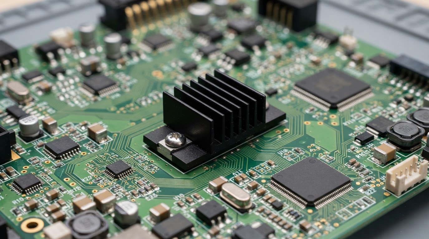
Board-Level Heat Sinks, Matched to Your PCB
Control component temperature without compromising electrical clearance, board space or repeatable assembly. Morton develops compact aluminum and copper heat sinks around your device and operating conditions.
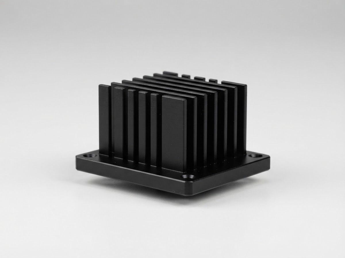
Compact Cooling at the Component Level
A board-level heat sink transfers heat from a discrete power device or board-mounted package into the surrounding air. The interface, retention method and local airflow determine how well it works in your assembly.
Solve the Constraints That Actually Limit Your Board
Compact electronics need more than extra fins. We review the thermal, electrical and mechanical constraints together so the cooling part fits the complete design.
Temperature margin
Match power loss, inlet air and junction-temperature target before choosing geometry.
Crowded PCB layout
Define height, connector access and keep-out zones around the package.
Electrical clearance
Identify live tabs, creepage paths and insulating hardware early.
Assembly consistency
Control the interface and mounting load to reduce variation between builds.
Follow the Heat Path from Junction to Air
Each interface contributes to the final temperature rise. A clear thermal path helps you improve the part of the assembly that creates the greatest resistance.
Junction → Case
Use the device data and the relevant heat-flow path.
Case → Interface
Set material, contact area and controlled compression.
Interface → Heat sink
Maintain a flat, clean contact region and repeatable retention.
Heat sink → Air
Account for installed airflow, fin direction and nearby obstructions.
See the complete path
The smallest interface can become the dominant bottleneck.
Design for real conditions
Validate temperatures in the intended enclosure and board orientation.
Package Compatibility Without Assembly Surprises
We adapt the mounting concept to the package drawing and PCB layout, keeping thermal contact and electrical safety in the same review.
TO-220 Devices
Review tab contact, screw or clip retention and lead access.
- Check live-tab isolation.
- Define lead-to-sink clearance.
TO-247 Devices
Provide a contact region and mounting load suited to the larger package.
- Verify package-specific loading.
- Preserve adjacent component space.
BGA & Board-Mounted Packages
Align the top interface and board retention with the actual package stack.
- Protect the package from excessive load.
- Keep connector and service access.
Send the package drawing and the PCB keep-out envelope.
Check Package CompatibilitySize the Heat Sink Around a Thermal Budget
Start with allowable temperature rise and dissipated power. Then allocate resistance to the device, the interface and the heat sink in the actual cooling environment.
- Dissipated power, not rated electrical power.
- Maximum inlet-air temperature.
- Junction-temperature design target.
- RθSA heat sink to ambient
- RθJC junction to case
- RθCS case to heat sink
Validate the result
Critical physical boundary parameters to confirm during evaluation
Bring your power loss and temperature target for a focused review.
Build Your Thermal BudgetFit the Cooling Surface into Your PCB Envelope
Footprint, height and attachment features are developed together so the heat sink clears nearby parts and supports repeatable placement.
Keep-out definition
Include connectors, test points, tall capacitors and service access.
Fin orientation
Align useful channels with the intended airflow or natural-convection path.
Contact region
Match the package surface and leave a practical tolerance stack.
Retention access
Provide room for clips, screws or board anchors and assembly tools.
Make the cooling concept fit before the PCB layout is frozen.
Review Your PCB EnvelopeChoose Material and Finish for the Interface
Aluminum and copper provide different balances of weight, heat spreading and manufacturing cost. Surface finish is selected with the contact region and electrical requirements in view.
Aluminum
A practical balance of low mass, useful surface area and production cost for compact board cooling.
Copper
Useful where local spreading or a restricted envelope supports the additional mass and cost.
Balance heat spreading, handling and final assembly cost.
Discuss Material and FinishControl the Interface. Protect the Circuit
The right interface combines useful heat transfer with the insulation and mechanical behavior your package requires.
Thermal Contact
Select bond-line thickness and contact pressure around the actual surfaces. A thin interface is useful only when it makes reliable contact.
Electrical Isolation
Review the live tab, dielectric interface, shoulder bushings and clearance as one system where isolation is required.
Retention Stability
Match clip force, spring travel or fastener torque to the device and interface requirements.
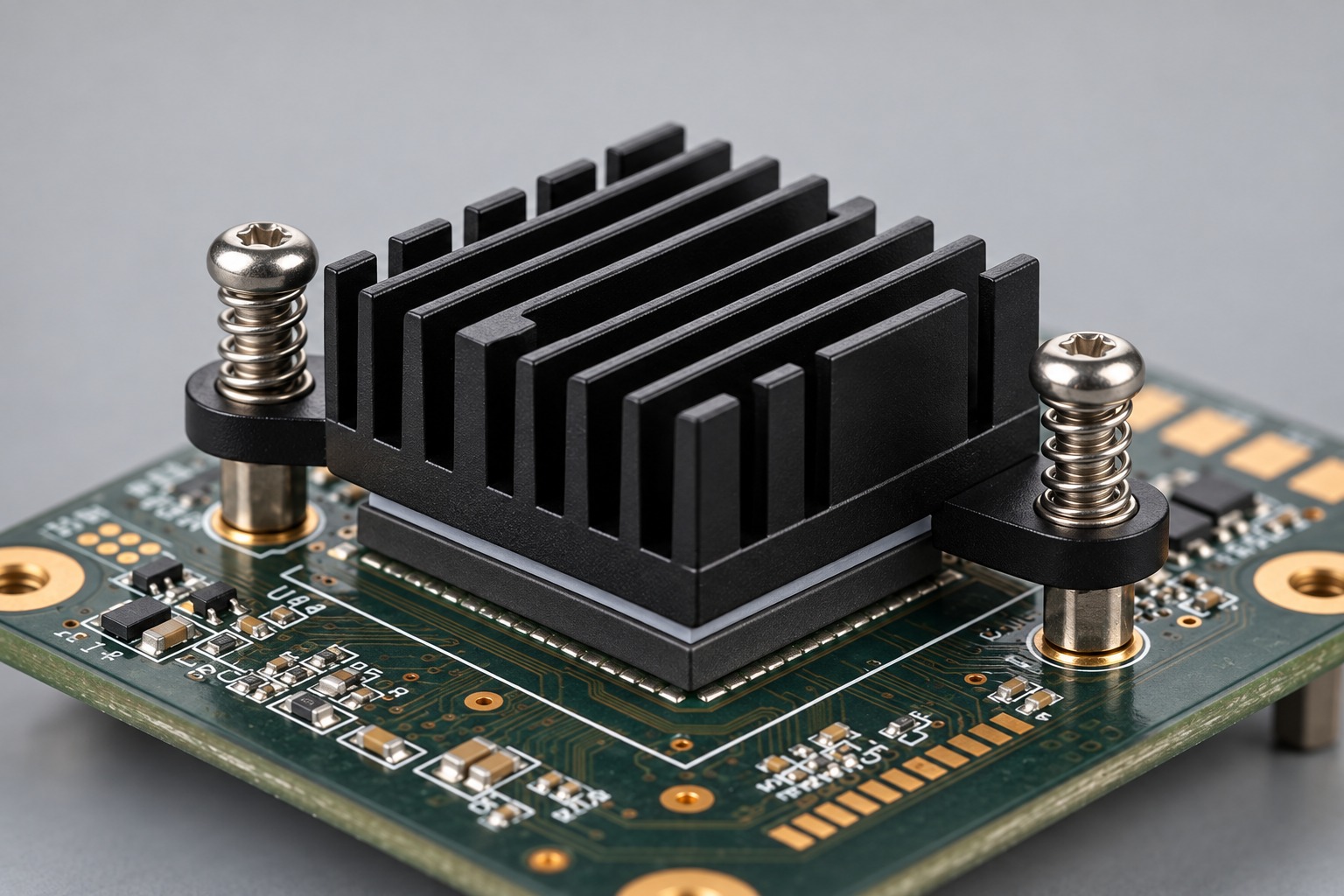
Retention Designed for Repeatable Assembly
A stable attachment maintains thermal contact through handling and operation while keeping package and board loads under control.
Define the load path
Carry retention loads through suitable package or board features.
Select the attachment
Compare clips, spring fasteners and approved board retention features.
Set the installation method
Document loading, compression, tool access and inspection criteria.
Verify the assembled board
Check package stress, movement, clearance and thermal contact after assembly.
Board Cooling for Real Industrial Electronics
Compact thermal parts support power conversion, control and connectivity where space and reliable operation matter.
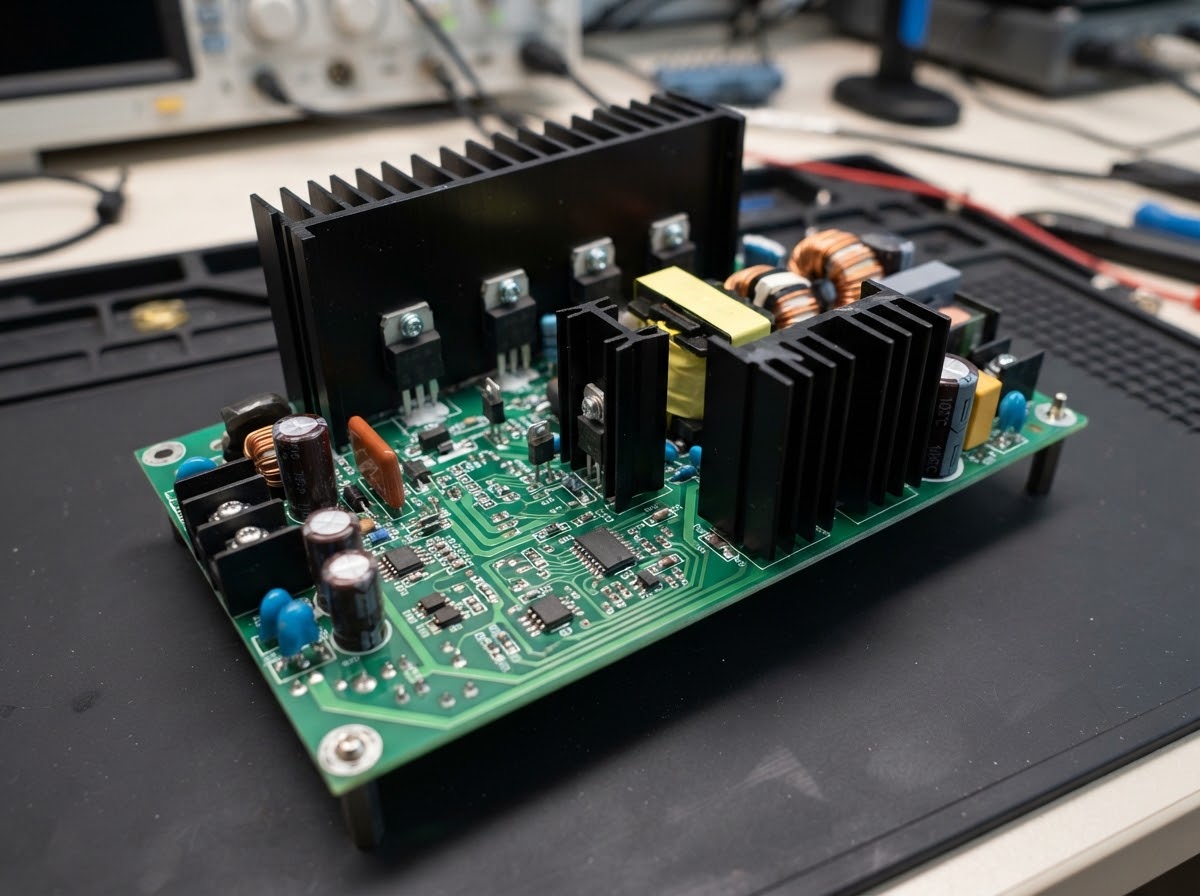
Industrial Power Supplies
Cool rectifiers, switching devices and local conversion stages within a constrained power board.
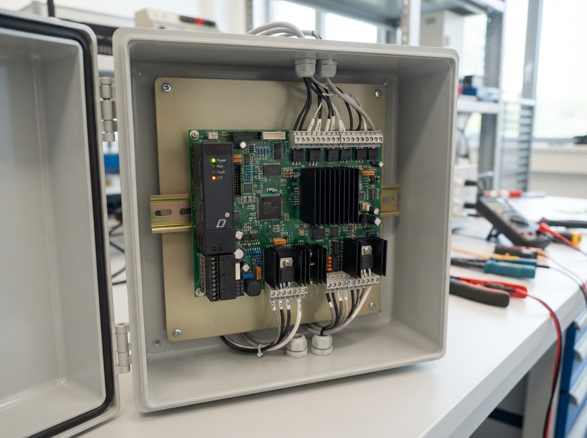
Automation & Control
Manage device temperatures around dense control electronics and limited airflow.
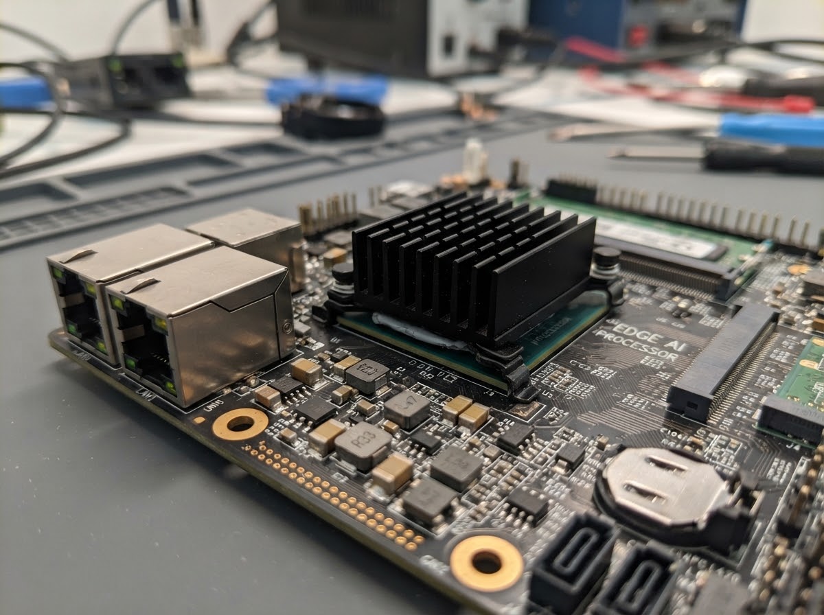
Industrial Computing & Networking
Support local hot spots near DC/DC stages and board-mounted processing devices.
Show us the board and the operating environment behind your application.
Discuss Your ApplicationVerify the Part and the Assembled Result
Inspection connects the controlled drawing to the actual board. Thermal evaluation is tied to documented conditions rather than an isolated headline number.
Dimensional checks
Verify contact areas, holes, overall height and the defined PCB envelope.
Surface and edge checks
Inspect finish coverage, masking, burrs and handling damage.
Assembly review
Confirm interface placement, retention and clearance on the intended stack.
Thermal evaluation
Record load, local air temperature, board orientation and measurement positions.
Define acceptance criteria before the first production batch.
Plan Your ValidationFrom Your Drawing to a Repeatable Supply Part
Engineering, sampling and production use the same revision logic so the approved design can move into your BOM with clear inspection and delivery requirements.
Requirement review
Package drawing, power loss, keep-out space, airflow and volume.
Design & DFM
Material, geometry, interface, retention and inspection features.
Sample approval
Confirm fit, function and agreed acceptance evidence.
Production release
Lock drawing revision, packaging, batch identity and release records.
RFQ essentials
2D/3D files, target quantity, finish, installation concept and delivery destination.
Supply coordination
Align forecasts, sample feedback and revision changes with a named project contact.
Move from a cooling concept to a controlled part in your supply chain.
Start Your RFQ ReviewQuestions Engineers Ask Before Selection
Resolve the key design assumptions early to keep package compatibility, validation and sourcing aligned.
Can one heat sink suit every TO-220 or TO-247 device?
Does a black finish guarantee electrical insulation?
Is a taller or denser fin arrangement always better?
Can a published thermal resistance be used directly on my PCB?
Can you supply the interface and mounting parts together?
What should I send for an initial review?
Have a package or integration question that needs a closer look?
Ask an Engineering Question
Let’s Review Your Board-Level Cooling Requirement
Send your package, thermal target and PCB constraints. We will help define a practical heat sink, interface and mounting concept for your next build.