

Thermal Management for Servers & Data Centers
Custom heat sinks and liquid cold plates engineered around your heat map, cooling conditions and server envelope—from prototype evaluation to repeatable production.
When More Compute Leaves Less Thermal Margin
Higher component density exposes the limits of airflow, contact interfaces and cooling capacity inside the same server envelope.
Concentrated heat
Small CPU, GPU and power-device footprints create local hot spots that a larger heat sink alone may not resolve.
Restricted airflow
Dense fins, cables and neighboring boards change the fan operating point and reduce useful airflow through the heat sink.
Uncontrolled contact
Flatness, TIM thickness and mounting load can consume the temperature margin before heat reaches the cooling surface.
Liquid-loop constraints
Cold plate pressure drop, wetted materials and connection layout must work with the available loop.
Start with the Conditions Inside Your Server
We define the thermal and mechanical boundaries together, so the proposed component can be evaluated in your equipment.
Share your heat map, CAD envelope and cooling boundary.
Define My Design InputsCooling Components Matched to the Bottleneck
Select the heat-transfer route that fits your source density, airflow or coolant supply, and assembly constraints.
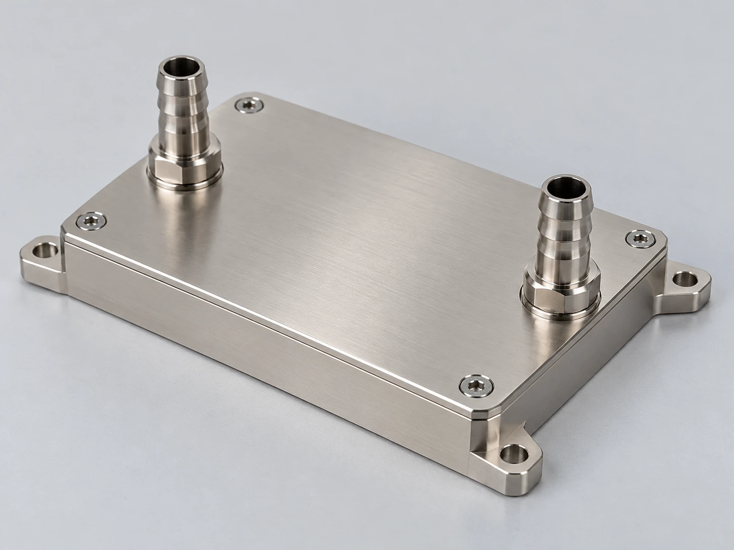
Liquid Cold Plates
Microchannel and machined flow-path designs transfer concentrated heat to the coolant while balancing pressure drop, cleanliness and material compatibility.
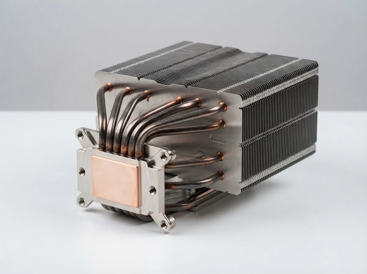
Heat Pipe & Vapor Chamber Assemblies
Spread localized heat and move it into an available fin area, with orientation, transport length and mounting load included in validation.
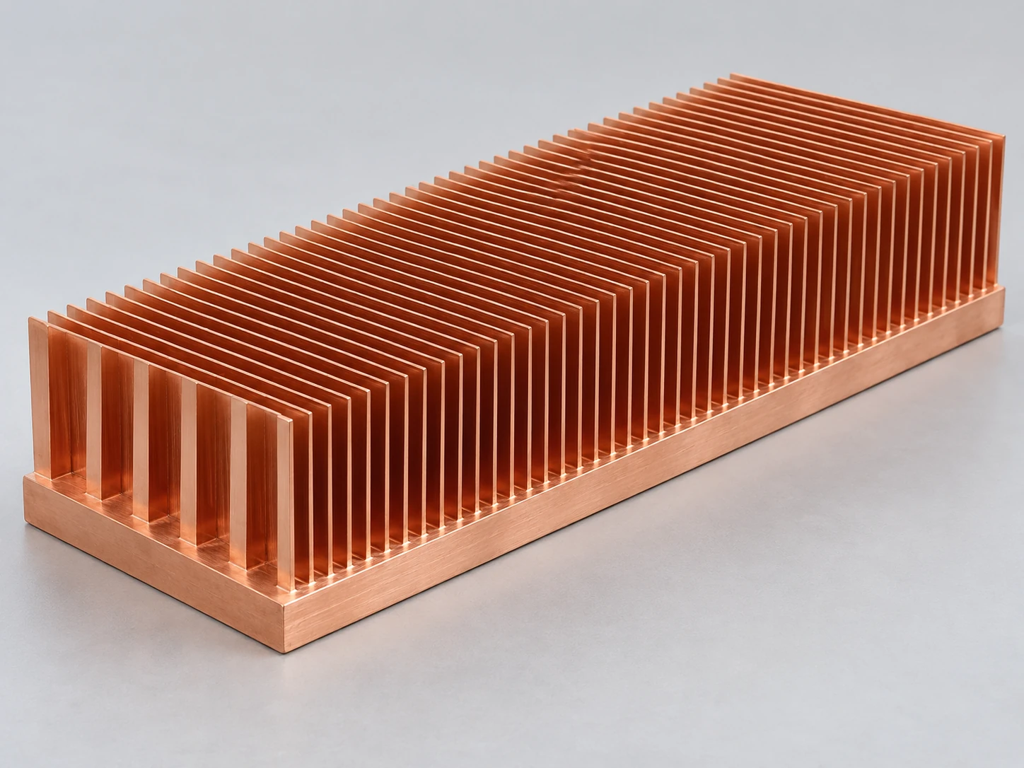
Skived Fin Heat Sinks
Integral copper or aluminum fins reduce the base-to-fin joint interface; fin spacing is matched to the installed fan pressure and airflow.
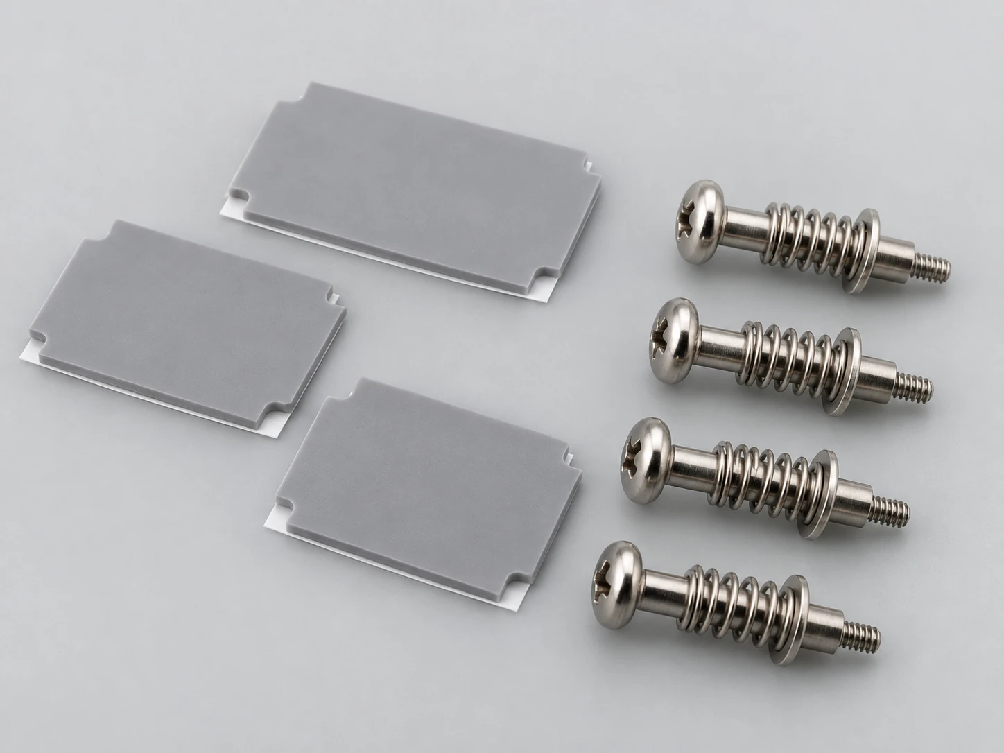
Thermal Interfaces & Mounting
Die-cut pads and spring-loaded hardware control the contact stack, helping reproduce the approved assembly condition.
Compare component options against one common set of operating conditions.
Select a Cooling RouteDifferent Server Loads. Different Cooling Priorities
We focus the component design on the thermal problem at each location, rather than treating the rack as a single heat source.
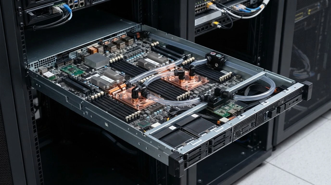
CPU & Accelerator Nodes
Concentrated chip heat and tight board keep-outs call for cold plates or heat spreaders that preserve the mounting and service envelope.
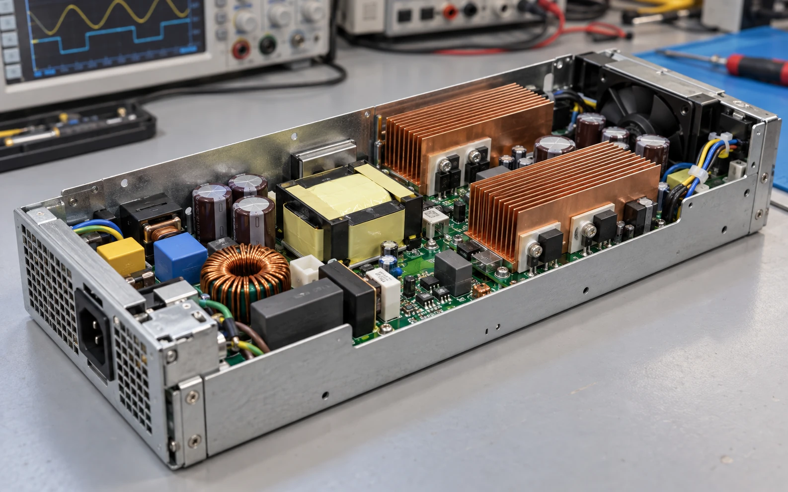
Server Power Supplies
Dense switching devices and constrained airflow call for copper skived fins, controlled interfaces and a verified installed fan operating point.
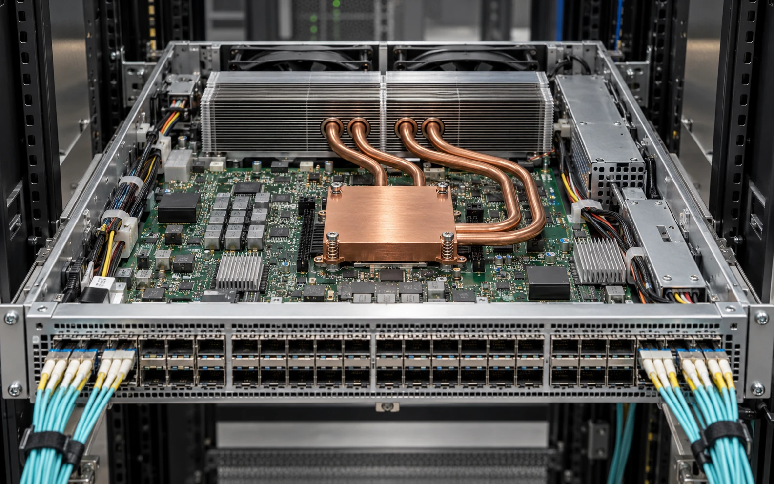
Networking & Storage Platforms
Distributed chip, power and memory loads call for directed airflow, heat-pipe assemblies and interface components that fit the board layout.
Design the Cold Plate as Part of the Loop
Thermal resistance is one requirement. A reliable liquid-cooled assembly also needs hydraulic, material and connection compatibility.
Flow & pressure drop
Evaluate the cold plate at the specified coolant viscosity, flow and inlet temperature, including flow distribution across the heat source.
Coolant & wetted materials
Review the metal, coating, seals and coolant together to manage corrosion and long-term compatibility.
Cleanliness & service
Define particle control, flushing, draining and connector access before the channel geometry is frozen.
Sealing & installation
Agree port orientation, fitting loads, mounting clearances and the leak-test acceptance method.
A Server PSU Case with Reproducible Conditions
A copper skived fin design helped a German server power-supply OEM recover temperature margin within a fixed component envelope.
- 250 W effective heat load
- 30 × 30 mm heat source
- 100 × 100 × 35 mm envelope
- 25 °C inlet air
- 60 m³/h measured through-fin airflow
- C1100 copper · 0.5 mm fins · 1.2 mm clear spacing
- 0.2 mm controlled TIM with spring-screw mounting
Validate the Conditions You Will Actually Approve
Translate the prototype test into a clear acceptance plan that engineering, quality and procurement can use together.
Thermal & hydraulic performance
Record heat-source geometry, input power, sensor locations and inlet conditions, together with airflow or coolant flow and pressure drop.
Mechanical fit & contact
Check critical dimensions, flatness, keep-outs, TIM stack and mounting force against the approved drawing.
Liquid integrity
Define hydrostatic and gas leak tests for the approved pressure rating, and retain the acceptance records for each cold plate.
Repeatability & traceability
Link the drawing revision, material batch, first-article results and inspection plan to the supplied part.
Keep the Approved Design Consistent Through Production
Move from the first drawing review to repeat orders with one controlled component specification and a visible release process.
Confirm the heat map, cooling boundaries, installation envelope and annual demand; resolve manufacturability questions.
Produce the agreed sample configuration with controlled material, interface and drawing references.
Review first-article and performance results, close deviations and freeze the production specification.
Use batch traceability, agreed inspection and approved engineering changes to protect the released design.

Bring Your Server Cooling Challenge to Morton
Share the heat source, available cooling and installation envelope. We will help define a practical component concept and the next engineering step.