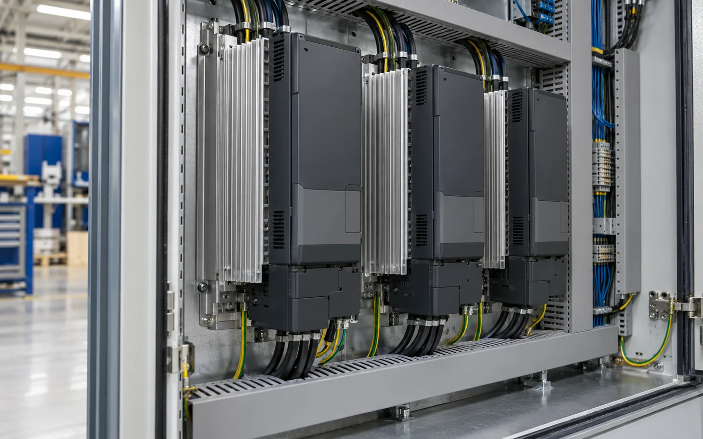
Variable-frequency drive cabinets
Manage distributed module losses, warm inlet air and filter resistance with accessible, directed air paths or a defined liquid loop.

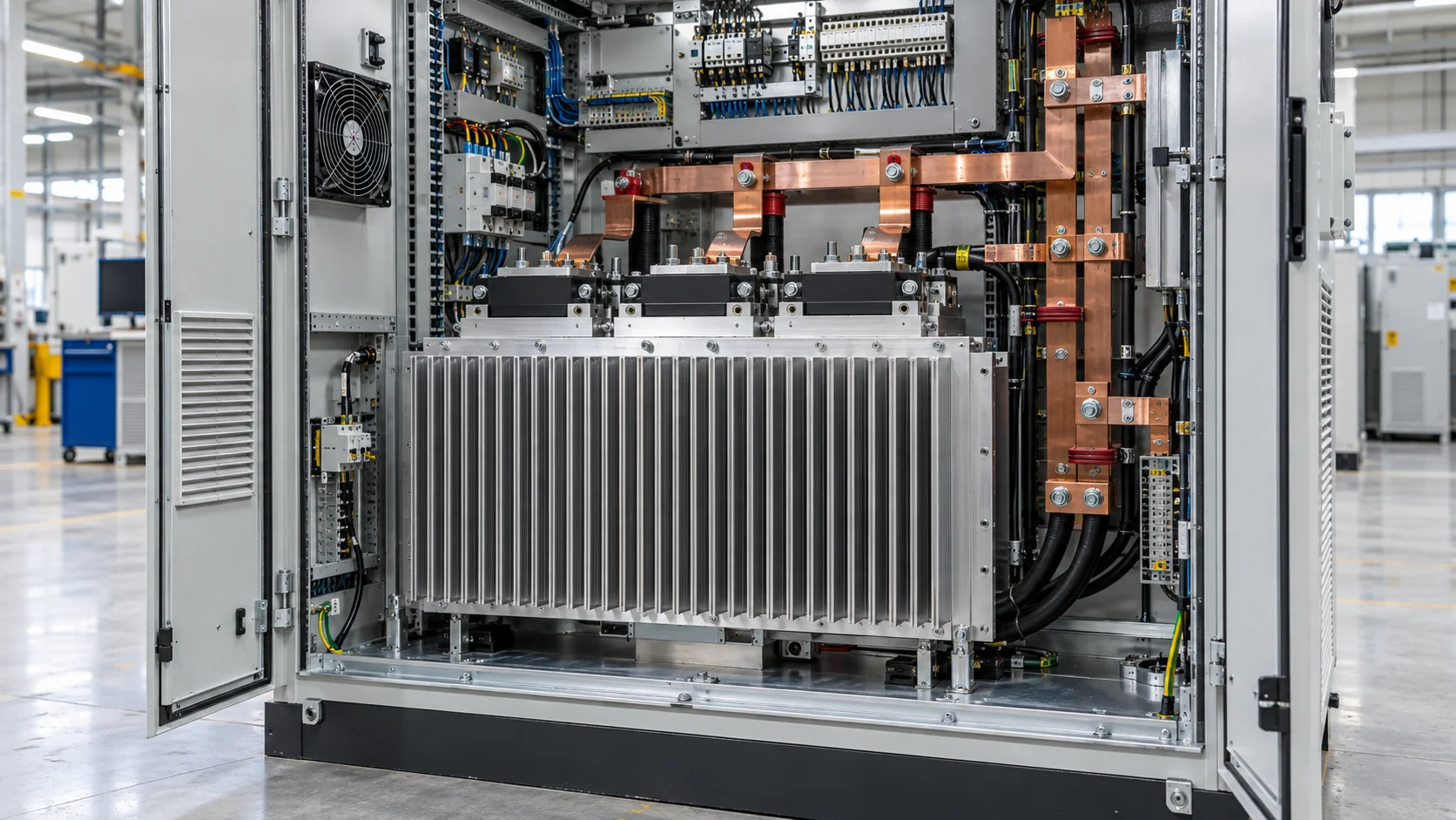
Custom heat sinks and liquid cold plates for IGBT and SiC power stages. Match cooling to your duty cycle, cabinet conditions and production requirements.
A drive that passes a bench test can still overheat inside a compact cabinet. Design around the conditions your equipment will actually face.
Repeated acceleration, braking and high-torque operation create changing losses. Define continuous and transient heat loads before sizing the cooler.
Filters, ducts and nearby components shift the fan operating point. Use the airflow through the heat sink, together with air pressure drop.
Smaller IGBT and SiC power stages concentrate heat at the mounting surface. Spreading resistance and interface quality can limit the whole assembly.
Thermal expansion, dust and coolant exposure affect joints and flow paths. Plan for connection integrity, cleaning access and material compatibility.
Start with the device temperature limit and actual cooling boundary. Then allocate the temperature rise across the package, interface and cooling assembly.
Give your next design review a cooling budget that can be checked.
Define Your Thermal BudgetCompare air, liquid and hybrid approaches against the same heat load, space and operating boundary.
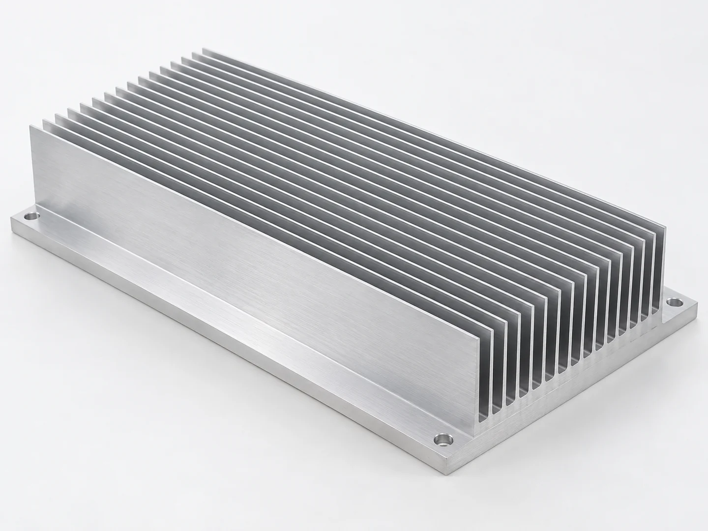
Extruded, skived and bonded-fin structures match fin area and spacing to the available fan pressure, enclosure space and cost target.
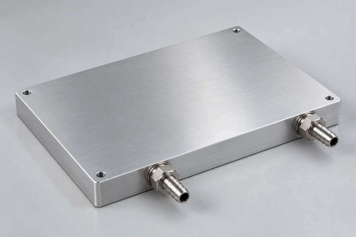
Tube-in-plate, vacuum-brazed and friction-stir-welded designs move heat from concentrated power stages into a defined coolant loop.
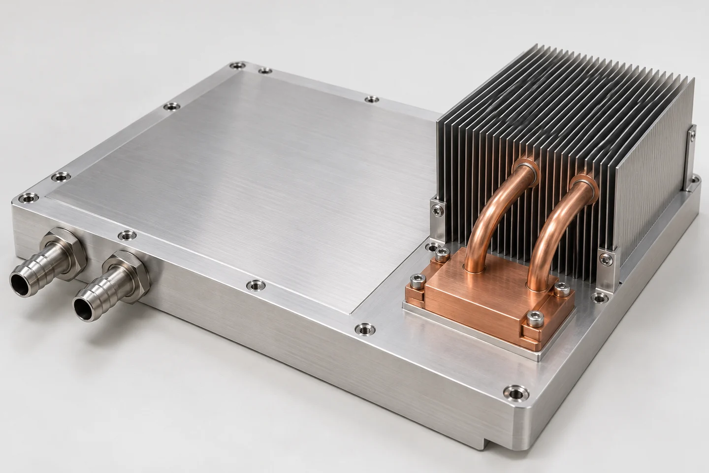
Liquid cooling handles the main power stage while fins or heat pipes manage auxiliary electronics within the same installation.
Compare the routes before committing your mechanical layout.
Compare Cooling OptionsDifferent power stages create different constraints. Match the heat path to the machine, cabinet and load profile.
Manage distributed module losses, warm inlet air and filter resistance with accessible, directed air paths or a defined liquid loop.
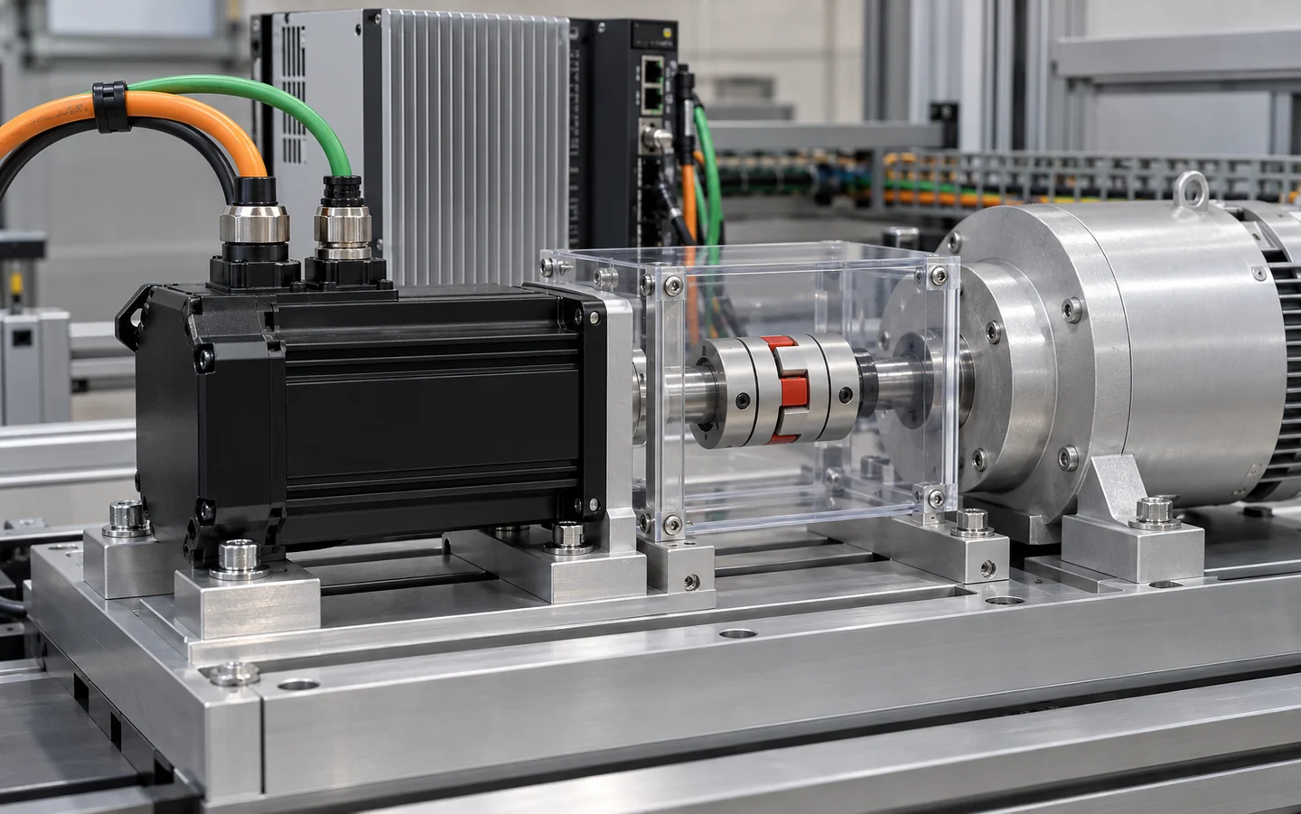
Address compact mounting, repeated acceleration cycles and vibration with controlled interfaces and installation-aware thermal design.
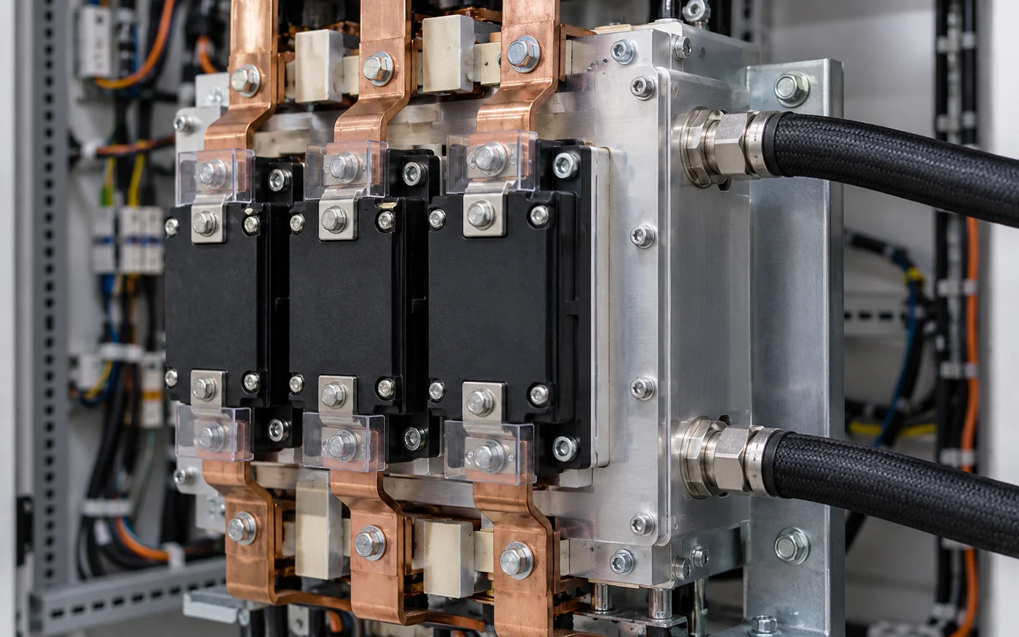
Balance multi-module heat spreading, coolant distribution and pressure drop for inverter, rectifier and energy-conversion platforms.
Start with the operating profile of your equipment.
Discuss Your ApplicationInterface plan defines fastener torque, compression percentage, contact planarity and wetted loop integrity before tool release.
Thermal performance depends on how the assembly is mounted and connected. Freeze critical interfaces before sample approval.
Define flatness, roughness and measurement span. Fine-machined interfaces can target Ra 0.8–1.6 μm and ≤0.05 mm flatness over 100 mm, subject to the approved drawing.
Select thickness and compression from the actual gap and device load limit. Confirm torque, spring force and mounting sequence with the module specification.
Match wetted metals, seals and inhibited coolant. Check corrosion risk, filtration, drainage and air removal as a single loop.
Review hole patterns, connector clearance, insulating requirements and coating masks. Keep thermal and grounding surfaces defined on the drawing.
Resolve mounting and loop details while changes are still inexpensive.
Review Your Installation InterfacesCompare results only when the heat-source layout, inlet condition and measurement method are defined. Our reports connect thermal results to a repeatable setup.
Define what a passing result looks like before testing begins.
Specify Your Validation Plan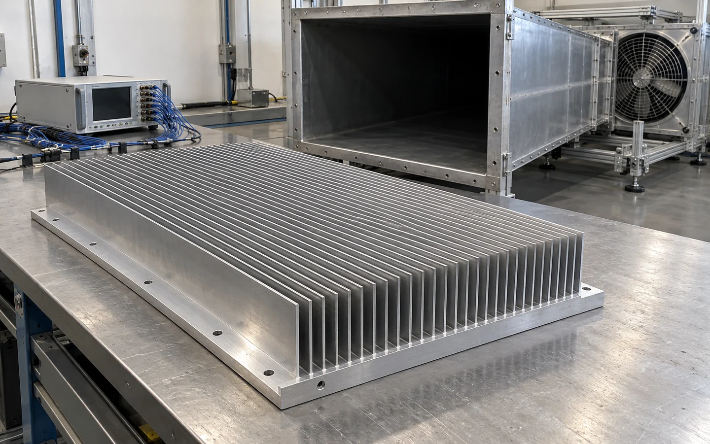
For a German industrial inverter OEM, a bonded-fin assembly managed six distributed power modules within a 400 × 600 × 100 mm envelope.
Test boundary: six 80 × 80 mm heat sources at 250 W each, 35 °C inlet air and 600 m³/h actual airflow. Equivalent resistance uses total applied power and the highest measured base temperature.
A 6061 baseplate, aluminum fins and a controlled 0.1–0.2 mm adhesive bond line supported the thermal layout. Joint appearance and sampled pull-off checks passed after 100 cycles from −20 to 80 °C.
Discuss a multi-module layout with defined operating and acceptance conditions.
Review a Similar Drive ProjectAlign engineering, procurement and quality around the same drawing revision, test conditions and release gates.
Share heat losses, source layout, operating temperatures, installation space and annual demand.
A reviewed requirement and boundary-condition list.
Compare cooling routes, confirm interfaces and complete DFM.
A proposed geometry, controlled drawing and agreed test plan.
Build samples and evaluate thermal, dimensional and connection performance.
Test records, first-article results and approved corrections.
Confirm the pilot build, labeling, packaging and change control.
An approved BOM, production acceptance criteria and delivery plan.
Start with the information you have; we will identify the remaining inputs.
Start Your Engineering Review
Tell us what your power stage needs to dissipate, where it must fit and how it will operate. Morton will help turn those boundaries into a practical engineering starting point.
Share a few details to start the engineering review.