
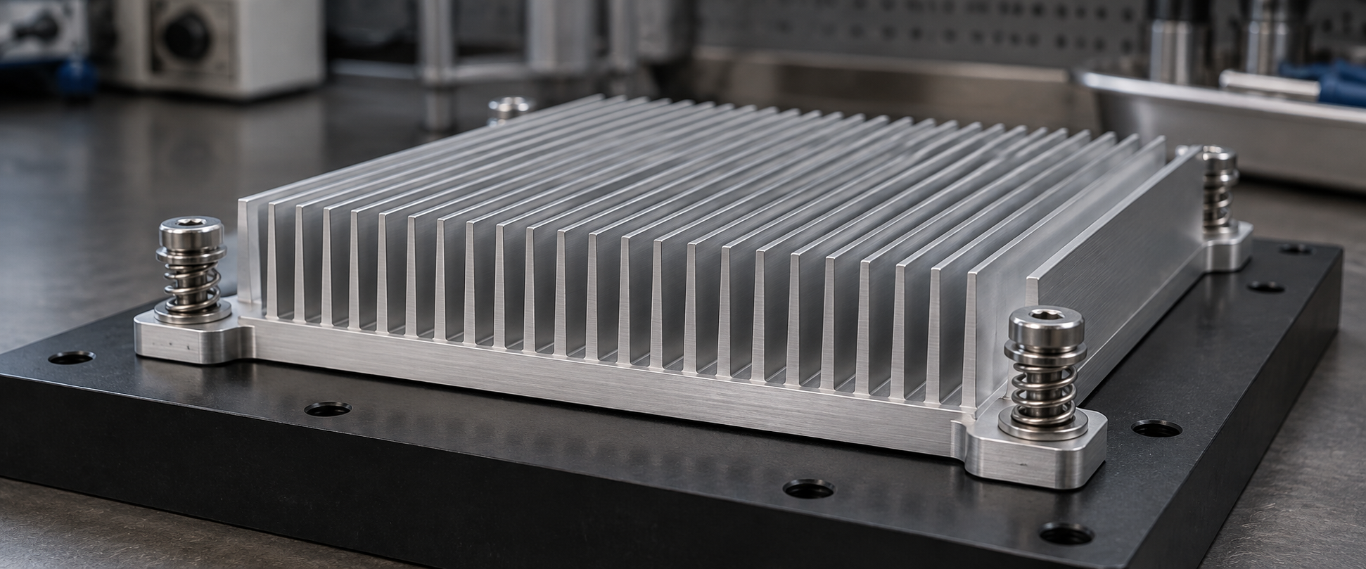
Heat Sink Mounting Hardware That Holds Thermal Contact
Engineered spring clips, spring-loaded screws and brackets help maintain the contact your heat sink needs—from the first prototype to repeat production.
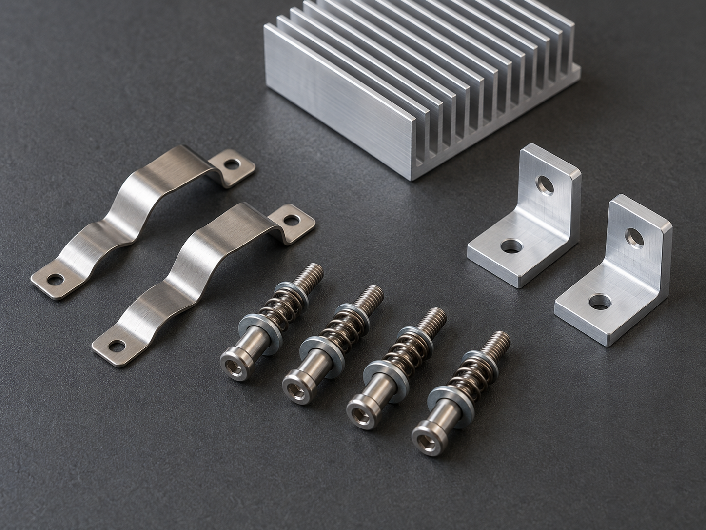
A Mounting System Built Around Your Thermal Stack
morton supplies mounting hardware as a coordinated part of your heat sink assembly, matching the fastener, spring and support features to the device, TIM and mounting structure.
Define the complete mounting stack before selecting individual parts.
Review a Matched Hardware KitAddress the Assembly Risks That Affect Thermal Contact
The right mount controls how load enters the assembly, so fit, contact and repeatability are considered together.
Uneven contact|Balanced fixing points and a defined tightening sequence help reduce tilted seating and local gaps.
Excessive device stress|Load limits and support positions keep clamping forces within the package and PCB design envelope.
Tolerance variation|Spring travel and mechanical stops manage the approved range of stack heights.
Assembly inconsistency|Captive parts, clear orientation and controlled instructions reduce missing components and rework.
Resolve the mounting risk before it becomes a production issue.
Review Your Assembly RisksChoose the Mounting Approach for Your Assembly
Compare attachment principles against access, load control and service requirements, then develop one configuration for your product.
| Mounting approach | Best suited to | Design focus |
|---|---|---|
|
Spring clips
|
Compact packages and accessible clip features | Contact location, clip deflection and insertion force |
|
Spring-loaded screws
|
Serviceable heat sinks with a controlled mounting stack | Working travel, shoulder or stop height and supported load path |
|
Bracket mounting
|
Enclosure-supported or heavier assemblies | Datum scheme, stiffness and access for tools |
|
Through-bolt support
|
Assemblies with underside access and a backplate | Electrical clearance, bearing area and PCB support |
Match the attachment principle to the structure you already have.
Select a Mounting ApproachControl Preload Across the Working Tolerance
Specify the force at the installed height, then check the complete tolerance range so the mount maintains contact without exceeding device load limits.
Define the compressed stack, spring seat and mechanical stop together.
Use the selected spring's load–deflection data at the minimum and maximum stack heights.
Review support locations, contact area and device-specific force limits.
Specify at installed height
Check the full tolerance stack
Define for the approved joint
Turn your stack dimensions into a defined mounting force window.
Discuss Preload and ToleranceMatch the Mount to the Thermal Interface
The fastener and TIM operate as one stack. Select the interface thickness and compression behavior before freezing the mounting height.
Soft thermal pads
Set the working gap from the specific pad's compression-stress curve. Mechanical stops help keep compression and device loading within the agreed range.
Grease and phase-change interfaces
Control flatness, seating and bond-line conditions. A repeatable assembly sequence supports consistent contact with the selected material.
Insulating interface sheets
Coordinate the sheet with sleeves and washers. Check edge coverage and local loading so electrical separation is preserved during assembly.
Coordinate the interface and hardware in the same engineering review.
Review TIM and Mount CompatibilityKeep Electrical Isolation in the Mounting Design
A thermal mount must also respect live parts, grounding paths and the electrical boundaries of the finished equipment.
Insulating sleeves and washers
Separate the fastener from live tabs where the approved stack requires isolation.
Creepage and clearance
Evaluate the nearest screw head, washer and bracket against the equipment's electrical design.
Defined grounding surfaces
Specify conductive contact zones and coating masks wherever a grounding path is required.
Protected interface edges
Control burrs, sharp corners and pad coverage to reduce the risk of insulation damage.
Share your isolation and grounding requirements with the mounting drawing.
Review Electrical InterfacesDesign Mounting Features That Fit the Heat Sink
Hole positions, tool access and support geometry are reviewed together to make your mount practical to machine and assemble.
| Interface | Engineering review |
|---|---|
|
Threads
|
M2–M8 common sizes; engagement and inserts to the approved design |
|
Mounting datums
|
Hole position, bearing surfaces and tolerance references |
|
Tool access
|
Driver envelope, assembly direction and surrounding component clearance |
|
Heat sink structure
|
Base thickness, fin clearance and support without obstructing the thermal path |
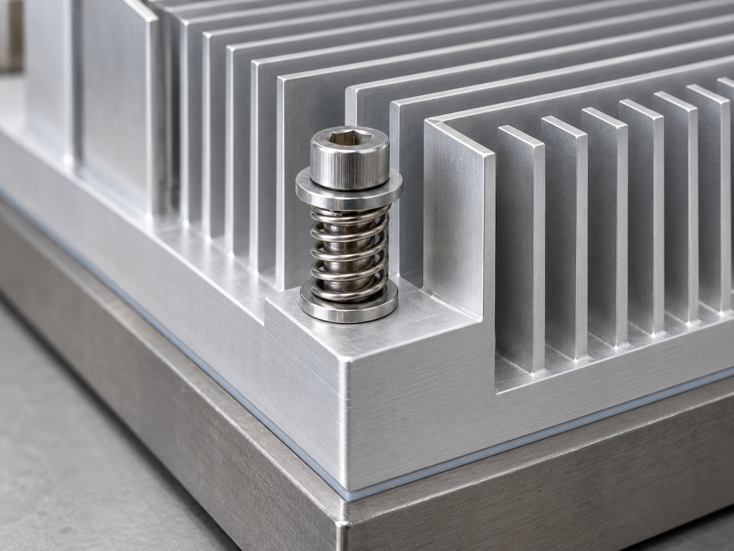
Check your interfaces before releasing the mounting drawing.
Request a Mounting DFM ReviewPlan Retention for the Operating Environment
Review the joint under the temperature, vibration and handling conditions your equipment will encounter.
Thermal cycling|Evaluate changes in preload and seating as the approved materials expand, contract and settle.
Vibration and shock|Define the retention method and test profile around assembly mass, orientation and support points.
Surface compatibility|Select finishes with the mating metals, moisture exposure and contamination requirements in view.
Service cycles|Check access, part retention and reassembly instructions where equipment needs maintenance.
Build the verification plan around your equipment's actual duty.
Define Mounting Validation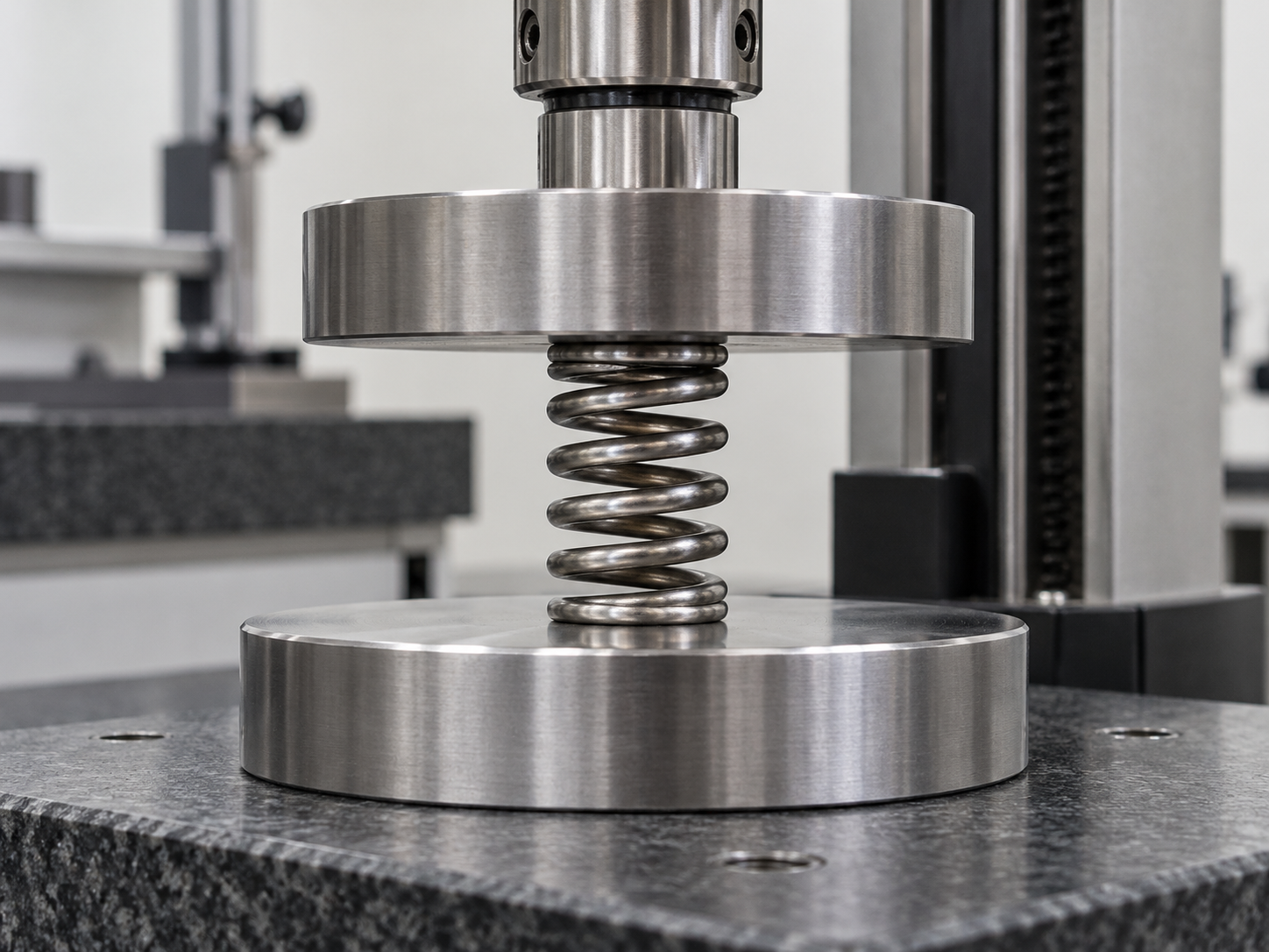
Inspect the Features That Make Assemblies Repeatable
Material, spring behavior and critical interfaces are linked to the approved drawing and inspection plan.
Specify the checks that matter to your receiving and assembly teams.
Discuss Your Inspection PlanMounting Hardware for Industrial Thermal Assemblies
Apply the same discipline to the mounting interface while adapting the support structure to the equipment.
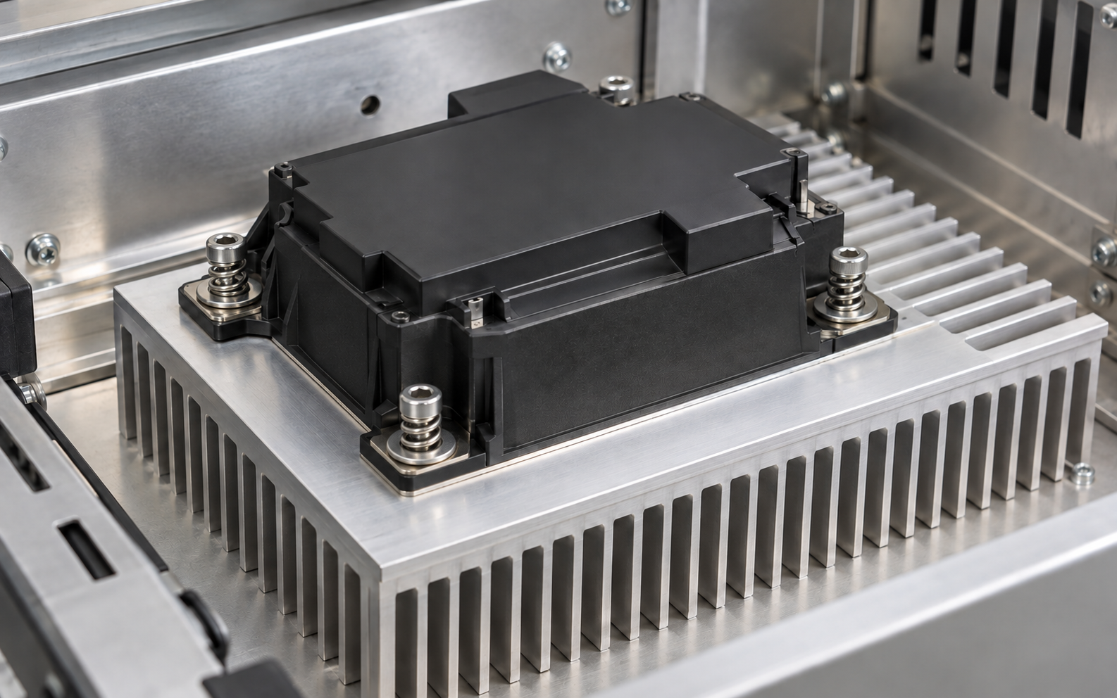
Power Electronics
Spring-loaded fixing points seat power devices against finned heat sinks while maintaining specified package loads.
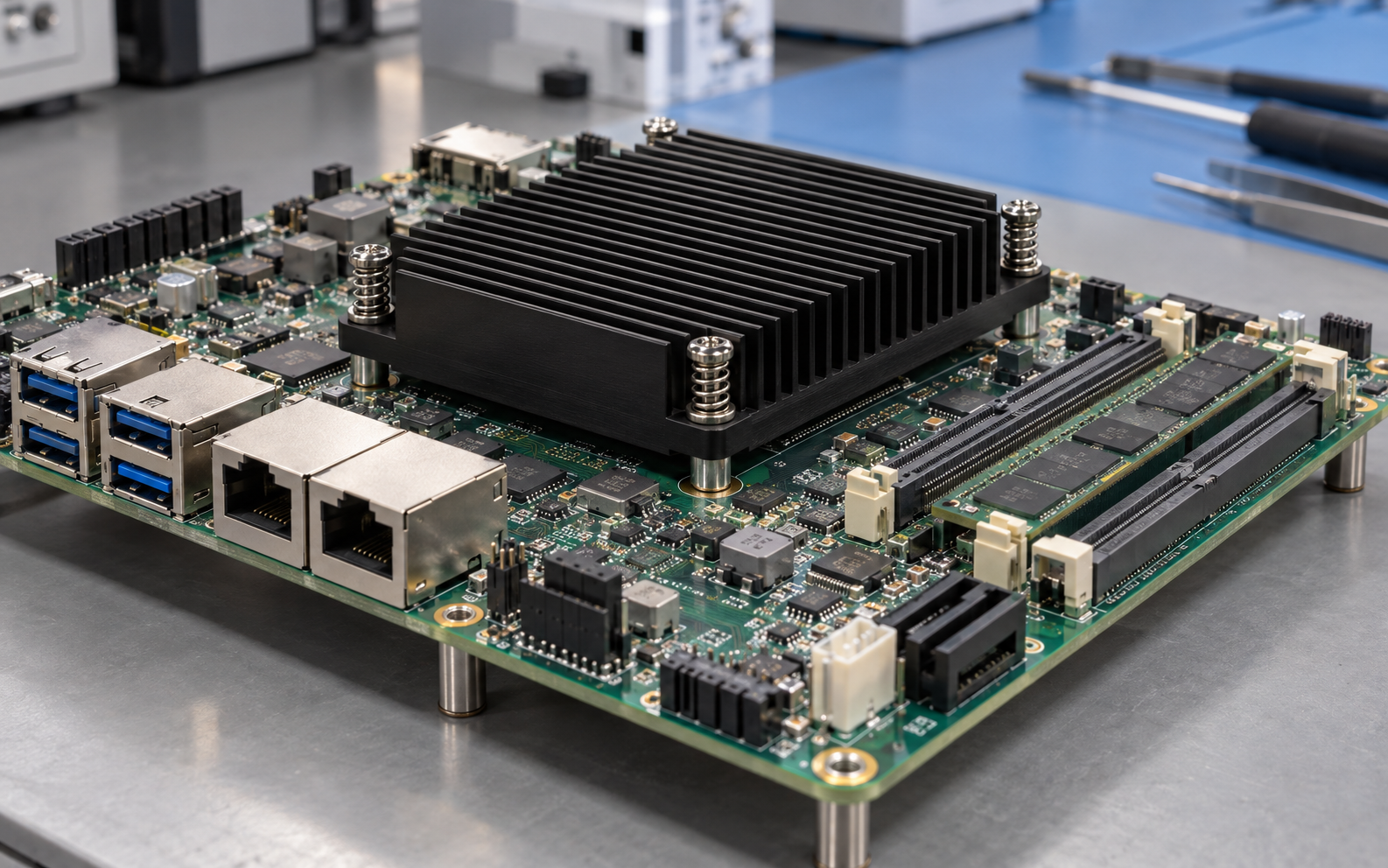
Industrial Computing
Low-profile mounts coordinate with PCB support, connector clearances and service access.
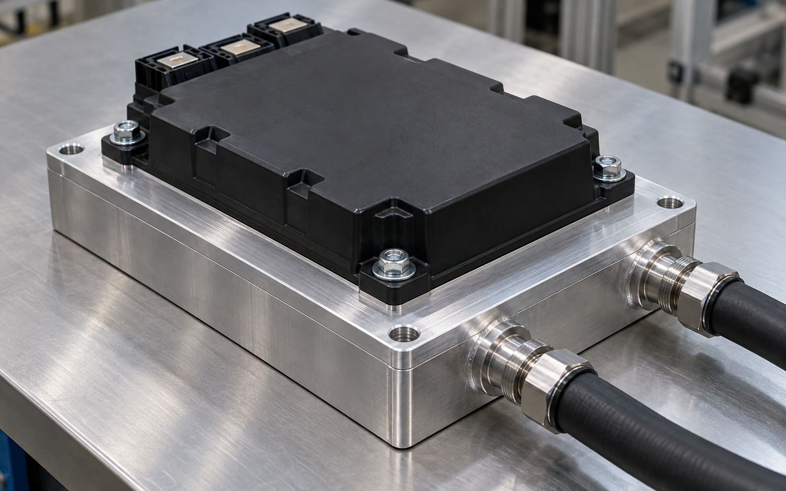
Energy Storage and PCS
Bracket and fastener interfaces secure power modules to liquid cold plates with defined load paths.
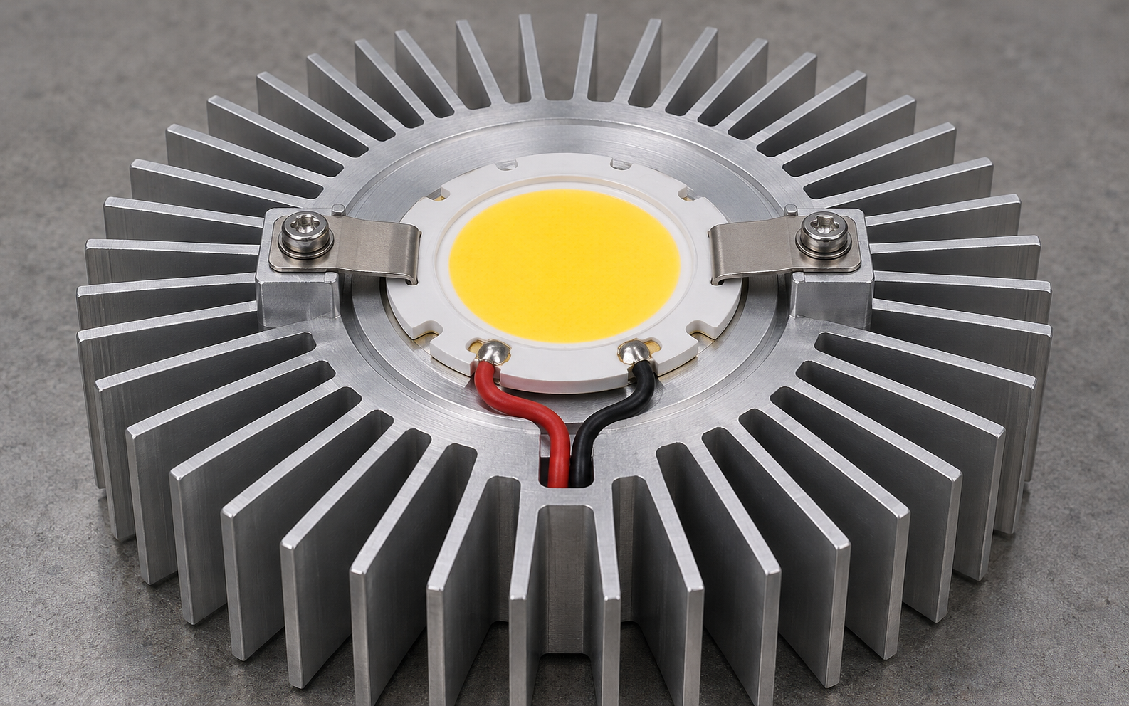
Industrial Lighting
Compact clamps and brackets retain thermal contact around LED modules within the available enclosure.
Develop the mounting interface for your equipment platform.
Discuss Your ApplicationMove from Drawing Review to Controlled Supply
One project team coordinates the mounting definition, samples and approved production configuration.
Review the stack
Provide device details, heat sink geometry, TIM and mounting limits for DFM.
Build and verify
Check sample fit, installed force and assembly sequence against the agreed requirements.
Approve the configuration
Freeze drawings, BOM, inspection points and packaging after validation.
Repeat with control
Supply identified batches and manage material or process changes through approval.
Start with a clear engineering definition and a practical sample plan.
Plan Your Sample BuildGive Your RFQ the Inputs Engineering Needs
A complete mounting brief helps us assess fit, load control and the supplied hardware boundary before quotation.
Send the information you have; we will identify the remaining inputs.
Prepare Your Mounting RFQHeat Sink Mounting Hardware Questions
Practical answers to the decisions that affect hardware selection, validation and supply.
Can you select a universal tightening torque?
Can the hardware be supplied with the heat sink?
Can you work from our drawings?
How do you control spring force?
What samples and documents can you provide?
Can the same parts be reused after service?
Get an answer based on your mounting stack and operating conditions.
Ask a Mounting Engineer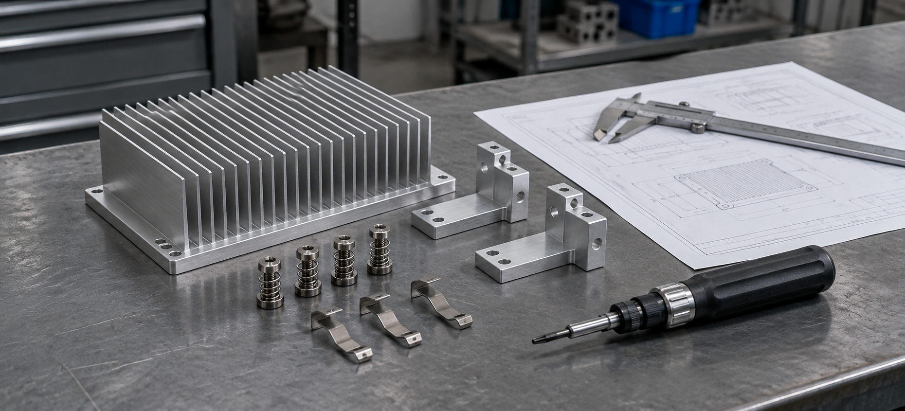
Build a More Repeatable Thermal Assembly
Tell us about the device, heat sink and mounting boundary. Our team will help define a coordinated hardware solution for your project.
-
Mounting DFM|Review fixing points, access and load paths.
-
Force and tolerance review|Coordinate installed height with device limits.
-
Matched BOM|Align the heat sink, TIM and specified hardware.
-
Sample support|Verify fit and assembly before production.
-
Controlled delivery|Receive agreed inspection records and batch identification.
Discuss Your Mounting Project
Share your application and the mounting details you already have.