
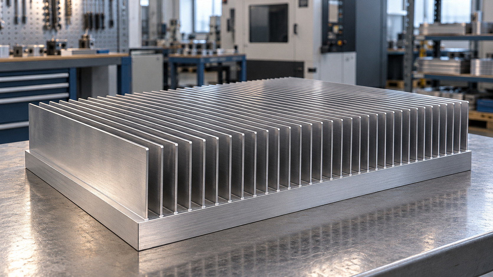
Bonded Fin Heat Sinks
Custom aluminum and copper fin assemblies for industrial drives, inverters and energy storage power conversion. Turn your thermal limits into a manufacturable, repeatable design.
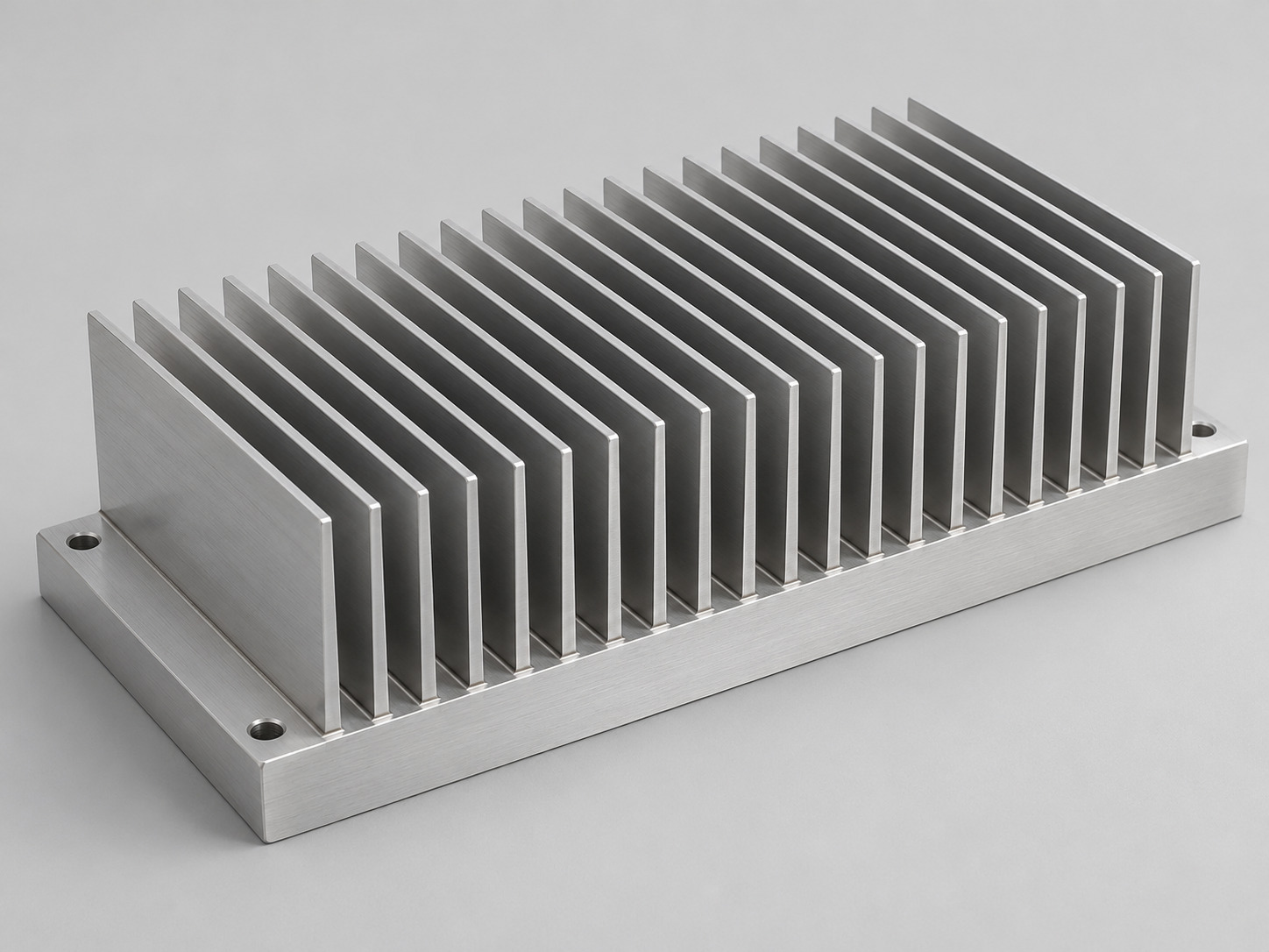
What Is a Bonded Fin Heat Sink?
Individual aluminum or copper fins are inserted into a grooved base and joined with a controlled thermally conductive adhesive. This construction allows a larger cooling surface and more flexible fin geometry than a single extruded profile.
More Design Freedom Where It Matters
Build the fin field around the system instead of forcing the system around a fixed profile.
Larger cooling footprints
Create broad fin arrays for distributed power modules without relying on one extrusion cross-section.
A better airflow match
Adjust fin height and channel spacing to balance heat transfer, air pressure drop and fan capability.
Material flexibility
Combine base and fin materials to balance heat spreading, weight and project cost.
Installation-ready geometry
Machine mounting holes, clearances and contact surfaces into a controlled assembly design.
Turn your space, airflow and cost constraints into a practical design.
Explore Your Design OptionsA Manufacturing Envelope for Larger Loads
Start with a clear mechanical scope, then refine the details against your application.
Integrated Thermal Assessment
Dimensions, fin geometry and mass are reviewed together with handling strength, bonding access and the device mounting pattern.
| Overall dimensions | 100–600 × 100–900 × 30–180 mm |
|---|---|
| Fin thickness | 0.5–1.5 mm |
| Maximum single-piece mass | 35 kg |
| Base and fin materials | Aluminum or copper |
| Local contact-face flatness | Typically ≤0.05 mm over 100 mm |
| Machined contact finish | Ra 0.8–1.6 μm where specified |
Share your drawing for a geometry and tolerance review.
Check Manufacturing FeasibilityThe Bond Line Is Part of the Thermal Design
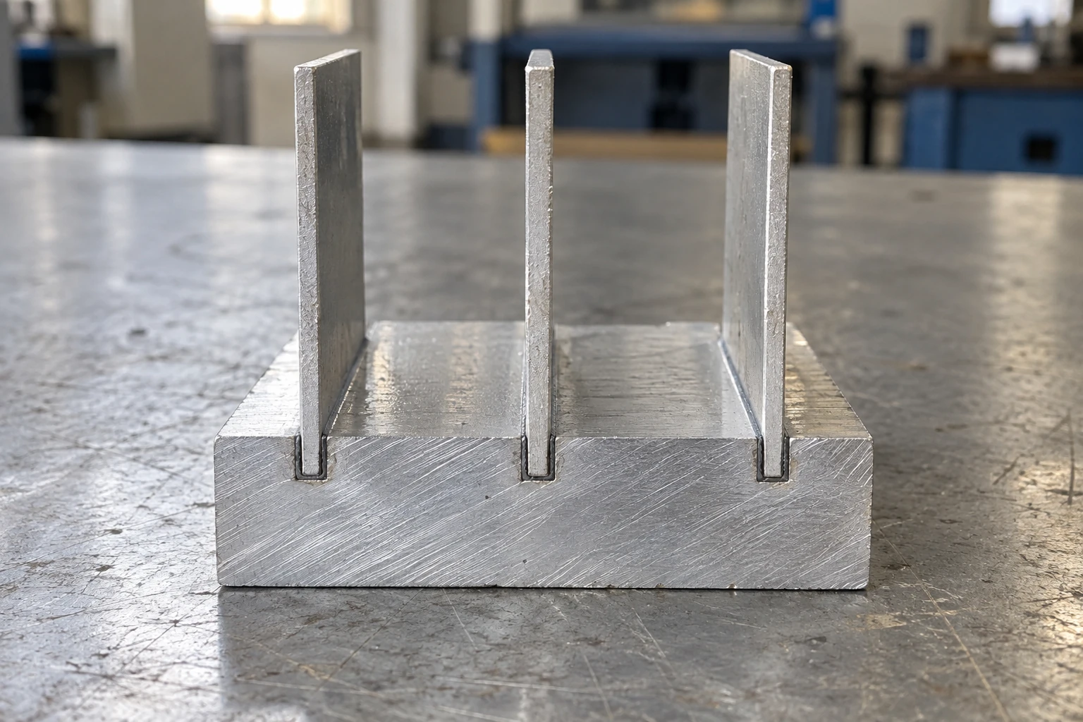
Build confidence in the joint before releasing the assembly.
Discuss Bond ValidationChoose Materials for the Whole Assembly
Aluminum base and fins
Copper where spreading matters
Select the material and finish combination that fits your operating environment.
Review Materials and FinishesDesign for the Air That Actually Reaches the Fins
Fin density only helps when the fan and duct can deliver the required flow through the assembly.
We assess the installed fan operating point, bypass paths and pressure drop through the fin channels. Spacing is selected for the enclosure, inlet conditions and maintenance needs.
Evaluating parallel fin channels against system resistance and bypass clearance.
Define the heat source
Record heat load, source area, mounting pattern and the permitted base temperature.
Use installed airflow
Measure the flow through the effective fin cross-section and record inlet air temperature and air pressure drop.
Compare like-for-like
Use the same heat source, interface, measurement locations and installation conditions when comparing designs.
Send your fan curve and operating limits for an airflow review.
Plan Your Thermal EvaluationBuilt Around Industrial Power Applications
Match a large fin surface to the heat sources, air path and service conditions of the equipment.
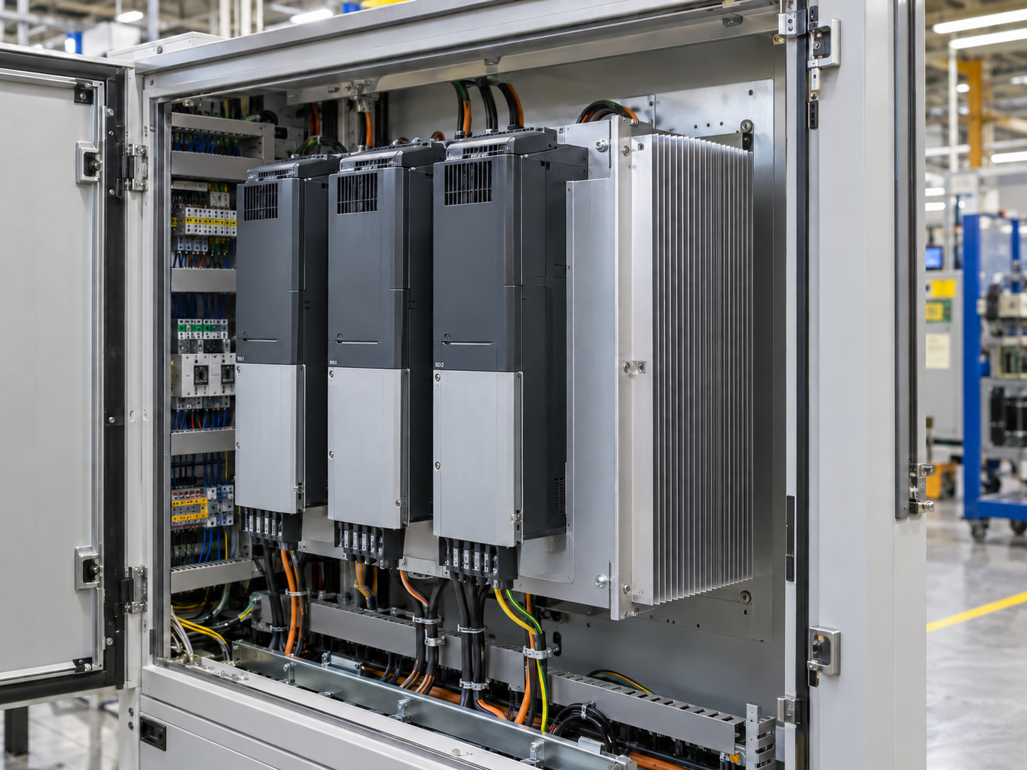
Industrial drives
Distribute IGBT or SiC module heat across a shared base while coordinating fin channels with the cabinet airflow.
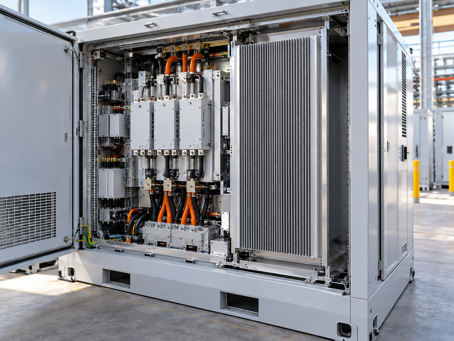
Energy storage PCS
Plan for converter duty cycles, elevated inlet temperatures and repeatable mounting across power modules.
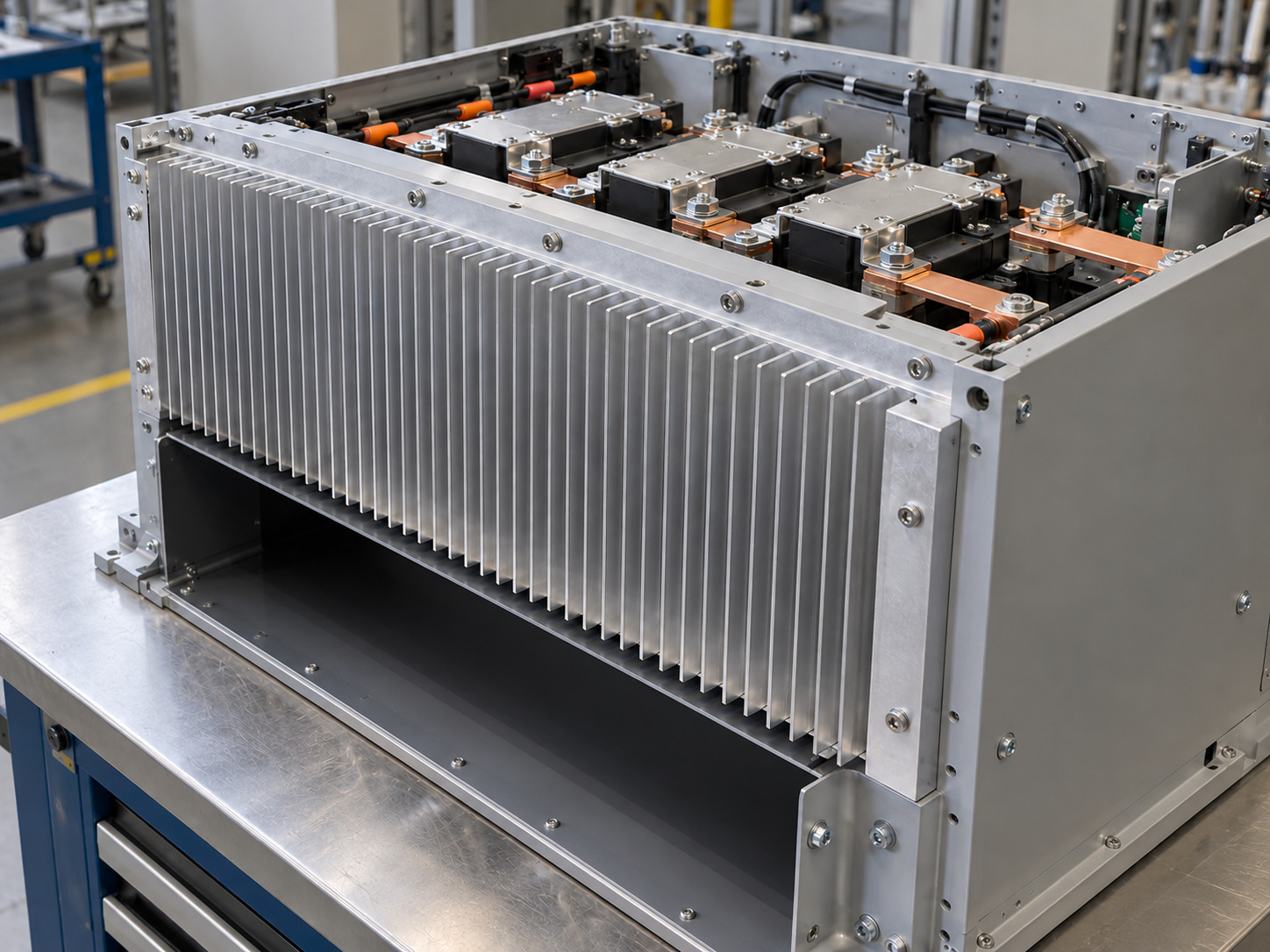
Industrial inverters
Integrate a large fin array with the enclosure, fan arrangement and access needed for assembly and maintenance.
Let us review the cooling requirements of your equipment.
Discuss Your Application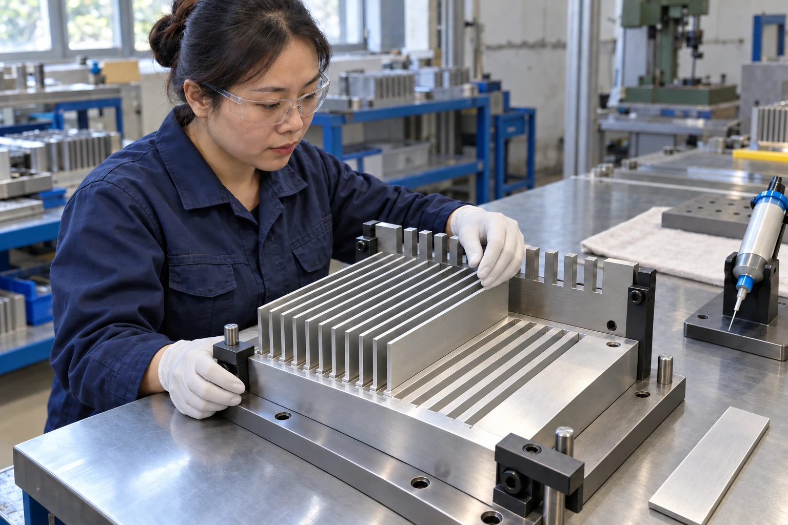
A Controlled Route from Base to Fin Assembly
Keep geometry, bonding and final interfaces connected through one manufacturing plan.
Machine the base
Create the grooves, datums and device interfaces from the released drawing.
Prepare the fin set
Inspect material, straightness and fin dimensions before surface preparation.
Bond and cure
Meter the adhesive, locate the fins in dedicated fixtures and apply the defined cure cycle.
Finish and inspect
Verify the final contact surface, mounting features, fin alignment and release documentation.
Align the drawing and process before your first sample build.
Start a DFM ReviewVerification You Can Carry into Production
Translate the approved sample into measurable controls for repeat orders.
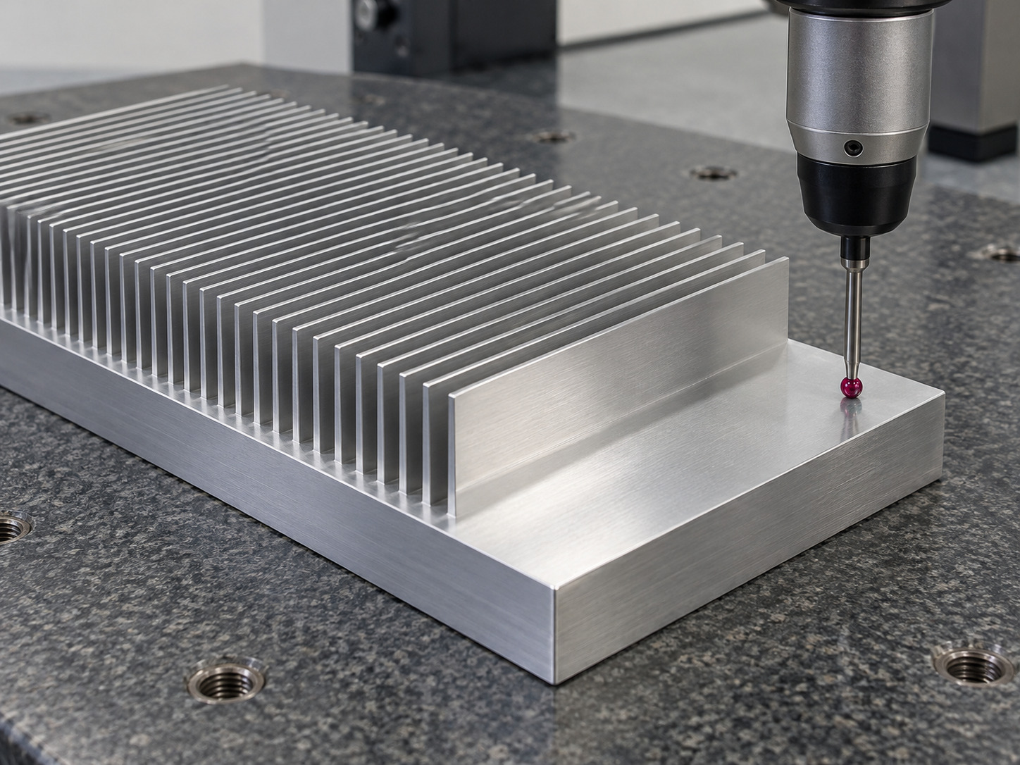
Inspect mounting datums, hole patterns, contact-face flatness and fin alignment.
Check fin retention and bond consistency using the agreed process and sample plan.
Record load, inlet temperature, installed airflow and measurement positions with the test result.
Link material lots, work orders, process records and inspection results; retain traceability records for five years.
Define the inspection and reliability evidence your team needs.
Build Your Inspection PlanEngineering Documents That Keep Teams Aligned
Give engineering, sourcing and quality a shared technical basis for approval.
Design package
- 2D drawings and STEP models
- Material and surface specifications
- DFM recommendations and interface details
Validation package
- Thermal test conditions and results
- Bond-strength and temperature-cycle scope
- First-article and critical-dimension reports
Production package
- Material certificates and CoC
- Agreed control plan and batch records
- Packaging specifications and engineering change history
Tell us which documents your approval process requires.
Define Your Document PackageA Clear Path from Sample to Repeat Supply
Move forward with defined inputs, approval gates and an agreed production schedule.
Requirements review
Share the drawing or thermal boundary conditions, expected quantity and project timing.
DFM and quotation
Review geometry, bonding requirements, inspection scope and cost drivers.
Sample approval
Validate the first article, thermal behavior and installation before freezing the design.
Batch release
Build to the approved revision and coordinate repeat deliveries with your forecast.
Map the sample and approval schedule for your project.
Plan Your Sample BuildGet a Quote Your Team Can Compare
A complete technical brief helps us price the assembly, tooling and validation on the same basis.
Technical Brief Checklist
Transparent Cost Scope
Prepare one clear brief for engineering and commercial review.
Request a Project QuotationBonded Fin Heat Sinks: Common Questions
Practical answers before you share a drawing or start a sample build.
When should I consider bonded fins?
Is the fin joint soldered or brazed?
Can aluminum and copper be combined?
Can you quote a fixed cooling wattage?
What is needed for an engineering sample?
How are the fins protected in transit?
Resolve the remaining technical questions with our engineering team.
Ask a Bonded Fin Question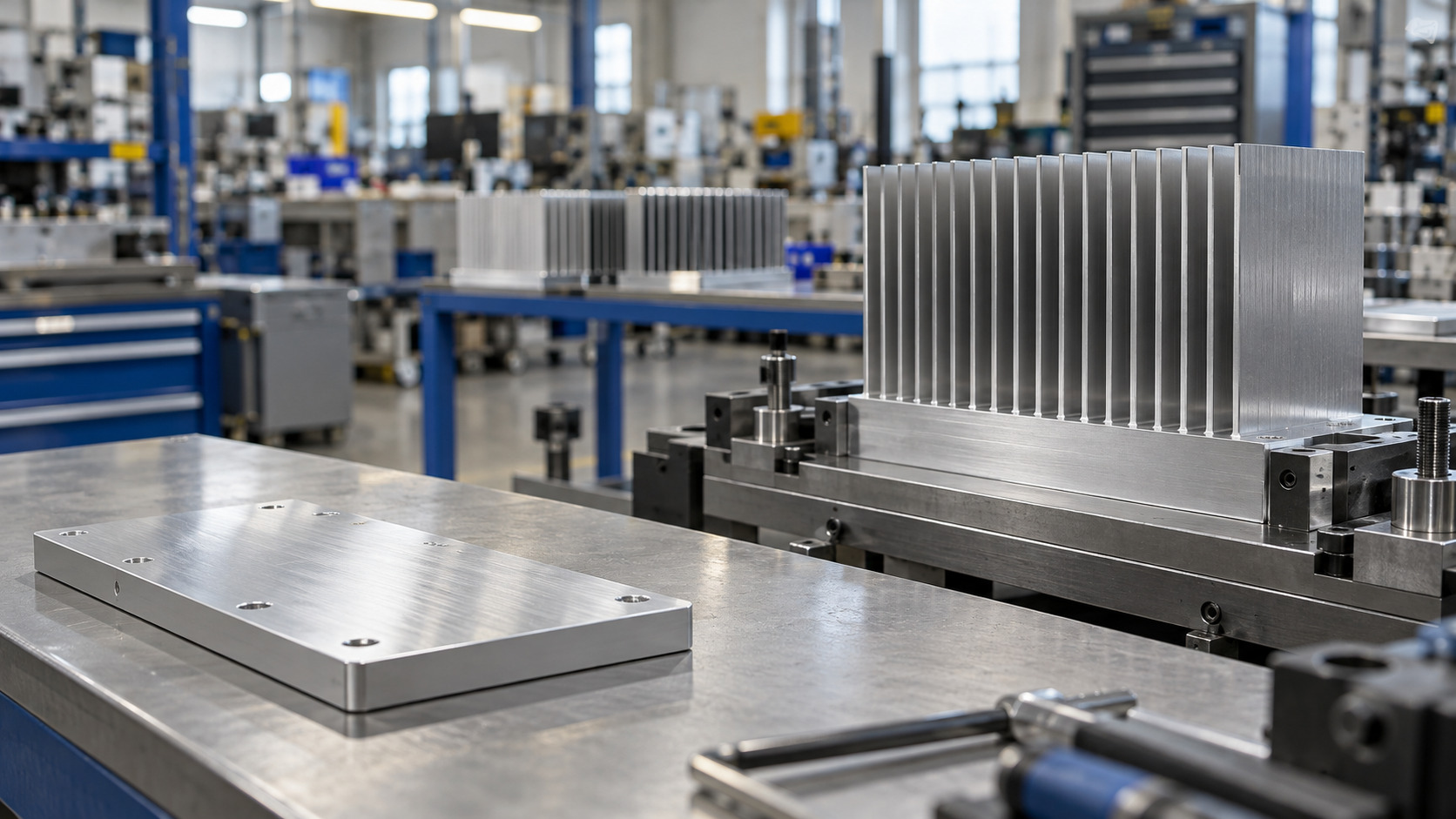
Let’s Engineer Your Bonded Fin Solution
Share your drawing or operating conditions. Morton will help turn the requirements into a practical sample and production plan.
Tell Us About Your Project
A drawing is helpful. A clear thermal brief is a good starting point too.