
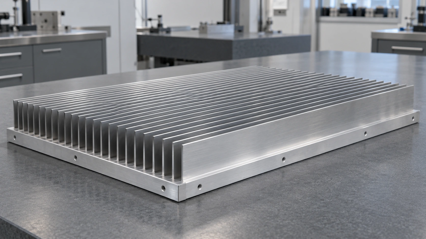
Bonded Fin Heat Sink for Industrial Inverters
How morton cooled six power modules within a 400 × 600 × 100 mm envelope—holding the hottest baseplate point to approximately 80°C at a 1.5 kW thermal load.
One Inverter. Six Heat Sources. A Fixed Envelope
A German industrial drive OEM needed a cooling assembly that matched its six-module layout, cabinet airflow and production requirements.
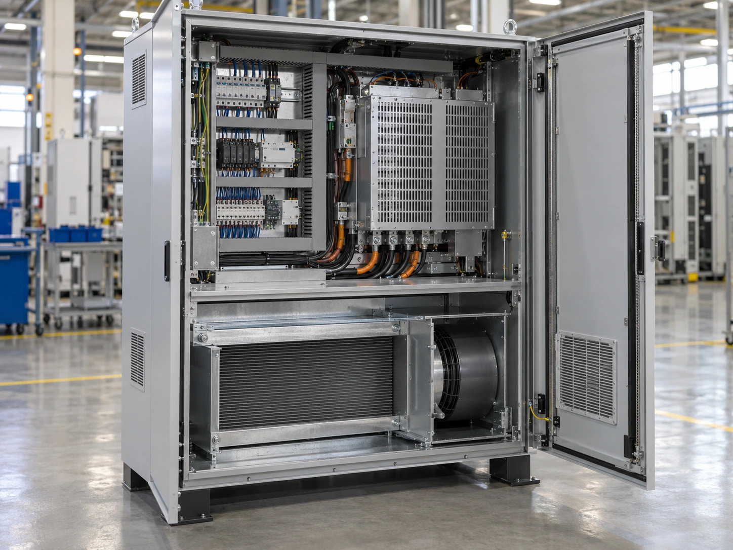
The Task: Stay Below 85°C Without Growing the Assembly
The design had to balance heat spreading, air-side performance and connection reliability within the customer's existing packaging limits.
Distribute 1.5 kW
Six separated heat sources required a baseplate that spread heat into the available fin area.
Use the available airflow
Fin spacing and the shroud had to match the installed 600 m³/h flow rather than a fan's free-air rating.
Hold the bond over cycling
The fin-to-base connection needed controlled adhesive thickness and mechanical verification after temperature cycling.
Resolve thermal, airflow and bonding constraints together.
TALK TO A THERMAL ENGINEER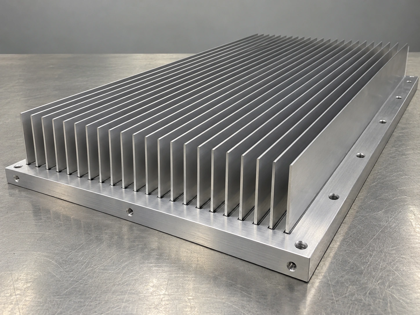
The Solution: A Bonded Fin Assembly Built Around the Heat Map
A machined 6061 aluminum baseplate and individually bonded aluminum fins created a large cooling surface while preserving the six-module mounting layout.
6061 aluminum baseplate
Machined mounting interfaces support consistent contact across the six power modules.
Separate aluminum fins
A bonded fin construction provides a large air-side surface within the specified height.
0.1–0.2 mm adhesive layer
Controlled thermal adhesive thickness limits variation at the fin-to-base interface.
Coordinated spacing and shroud
Module placement and ducting guide air through the active fin field.
Bring your module layout to the cooling design.
REQUEST A BONDED FIN REVIEWEngineering Parameters That Define the Result
The thermal result belongs to this geometry, heat-source arrangement and airflow condition. These parameters form the basis for a meaningful design comparison.
The Result: 80°C at the Hottest Baseplate Point
With all six sources operating at 250 W, the cooling assembly kept the maximum baseplate temperature approximately 5 K below the specified 85°C limit.
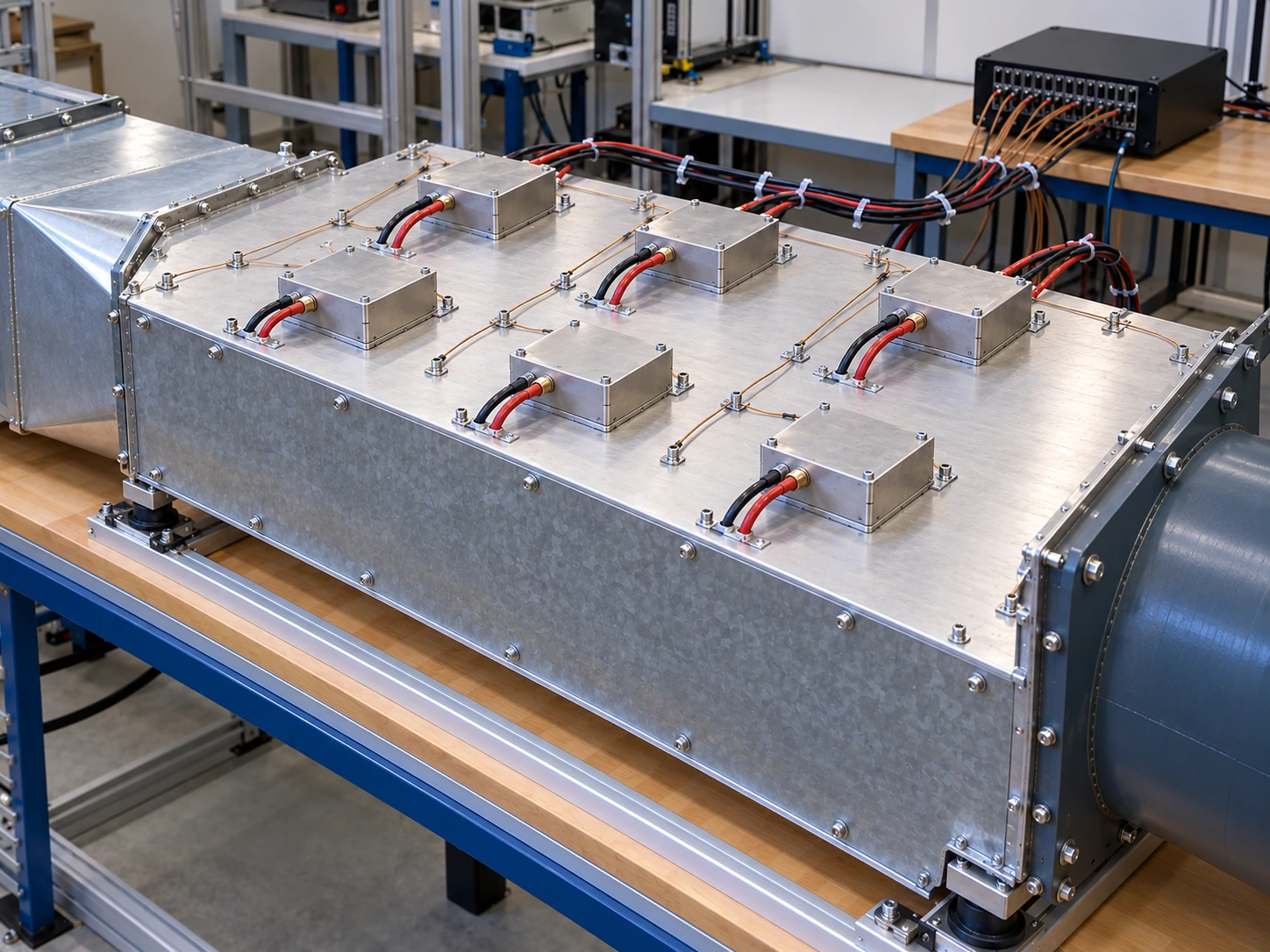
Validation Under the Conditions That Matter
The large assembly was evaluated in an extended air duct and alongside the customer's complete-system tests, preserving the defined six-source layout and operating airflow.
Make your validation conditions part of the specification.
PLAN A THERMAL VALIDATIONA Bonded Joint Needs More Than a Temperature Result
Adhesive control and post-cycle connection checks addressed the reliability of the fin-to-base interface before production release.
Control the bondline
The thermal adhesive layer was held within 0.1–0.2 mm to support repeatable fin-to-base contact.
Cycle the assembly
Samples completed 100 temperature cycles between −20°C and 80°C.
Check the connection
Post-cycle visual inspection and sampled fin pull-off checks passed the defined project criteria.
Define connection reliability before freezing the drawing.
REVIEW YOUR BONDING REQUIREMENTSFrom 30 Pilot Units to a 300-Unit Production Delivery
The design moved from pilot validation into the first production batch with the adhesive process and connection requirements carried into manufacturing.
Pilot build
Confirm assembly, manufacturing sequence and project acceptance requirements.
First production delivery
Transfer the approved bonded-fin design into repeatable batch manufacture.
Ongoing supply
Carry material, adhesive and inspection requirements into the production documentation.
Drawing and heat-source layout
Geometry, mounting interfaces and six-source arrangement.
Thermal validation conditions
Load, inlet temperature, actual airflow and measurement basis.
Bonding and cycling requirements
Adhesive layer control, cycling and connection inspection.
Manufacturing traceability
Material batches, work orders and first-article inspection records.
A large-area cooling assembly matched to the customer's heat map, with practical weight and machining-cost control.
Build a clear path from your prototype to production.
DISCUSS YOUR PRODUCTION PLAN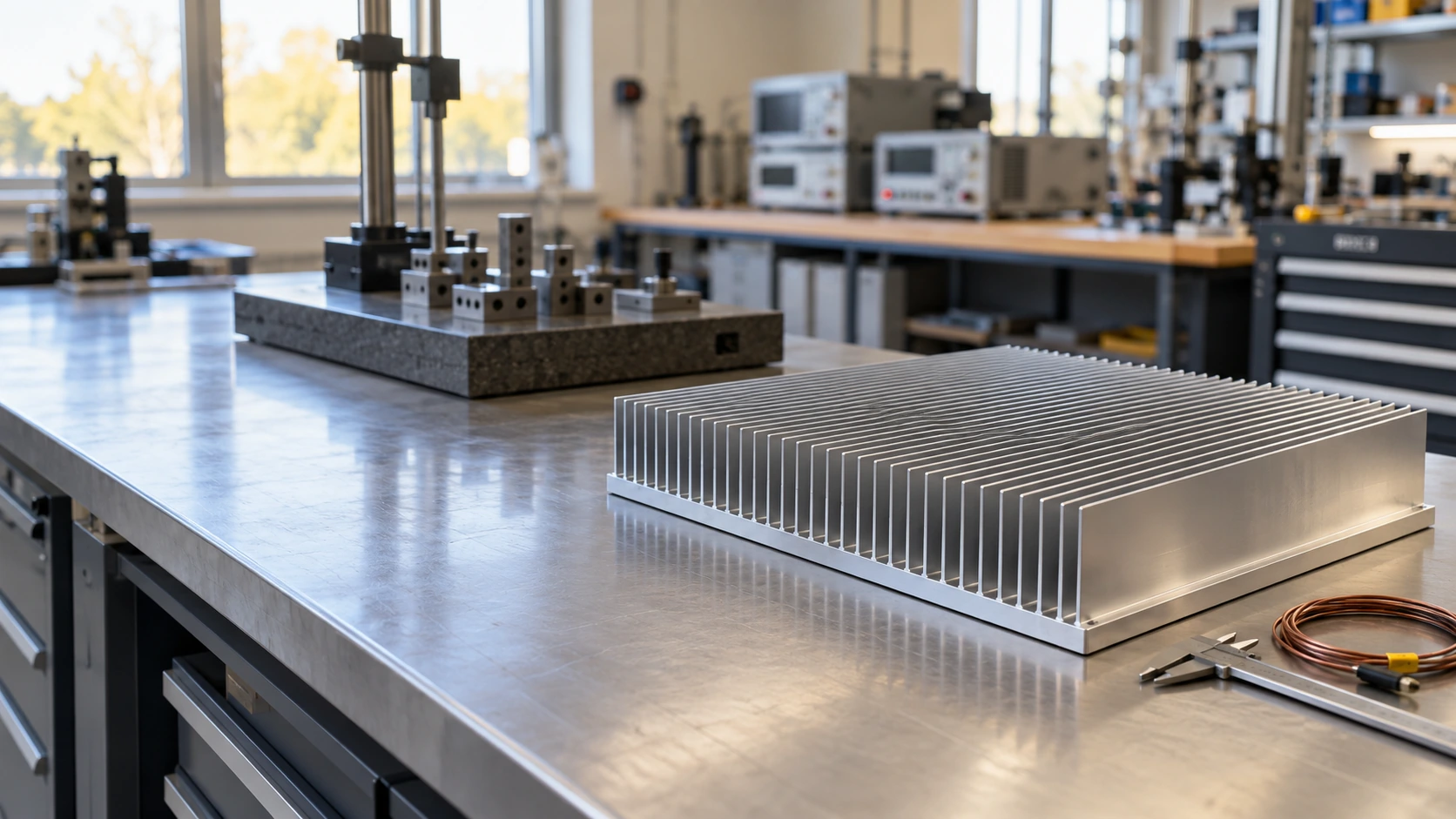
Bring Us Your Inverter's Thermal Challenge
Share the heat load, source layout and available airflow. Our engineering team can review a bonded fin cooling approach that fits your enclosure and manufacturing needs.
Application-led review
Start with the heat sources, enclosure and installed air path.
Thermal and mechanical alignment
Consider the baseplate, fin field, bonding and mounting together.
Prototype support
Evaluate the assembly before committing to production.
Defined validation conditions
Connect performance targets to a repeatable test setup.
Manufacturing continuity
Carry approved requirements into batch supply.