
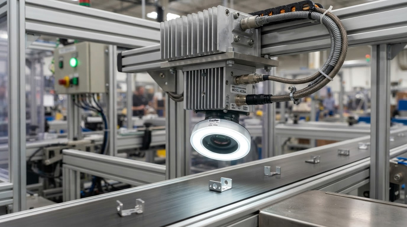
Thermal Stability for Every Inspection Cycle
Custom heat sinks, vapor chamber assemblies, liquid cold plates, and thermal enclosures for machine vision, industrial control, and automation platforms.
Match heat load, installation space, and operating conditions.
Carry approved drawings and test criteria into production.
Align thermal, mechanical, and manufacturing decisions.
Keep heat from setting the pace of your next machine.
Discuss Your Thermal RequirementsWhen Heat Becomes a Production Constraint
Compact electronics and demanding duty cycles leave little room for a thermal path that only works on the bench.
Rising camera temperatures
Heat from sensors and processing electronics can raise image noise and reduce operating margin.
Sustained edge-computing loads
Vision processors run inference continuously; insufficient cooling can trigger throttling and disrupt timing.
Dust-sensitive, enclosed equipment
Keeping contaminants out restricts the cooling air available to electronics.
Tight mechanical envelopes
Lenses, connectors, boards, and motion hardware compete for the same installation space.
Turn your operating constraints into a practical cooling brief.
Review Your Cooling ConstraintsProtect Image Quality, Cycle Time, and Uptime
A controlled thermal design supports the outcomes your customers expect from an automated production line.
Consistent inspection
More tuning effort and less repeatable inspection conditions.
Conduct heat away from the camera housing and validate temperature during image acquisition.
Predictable cycle times
Less compute headroom when sustained inspection workloads increase.
Spread local hotspots and verify cooling under representative continuous workloads.
Serviceable equipment
More maintenance intervention and stress on interfaces over the equipment lifecycle.
Match cooling architecture, mounting, and service access to the installation environment.
Build thermal headroom into the machine before the design is frozen.
Plan Your Thermal ArchitectureThermal Solutions Matched to Your Machine
Select the manufacturing route around the heat source, available space, and service conditions—not around a single standard part.
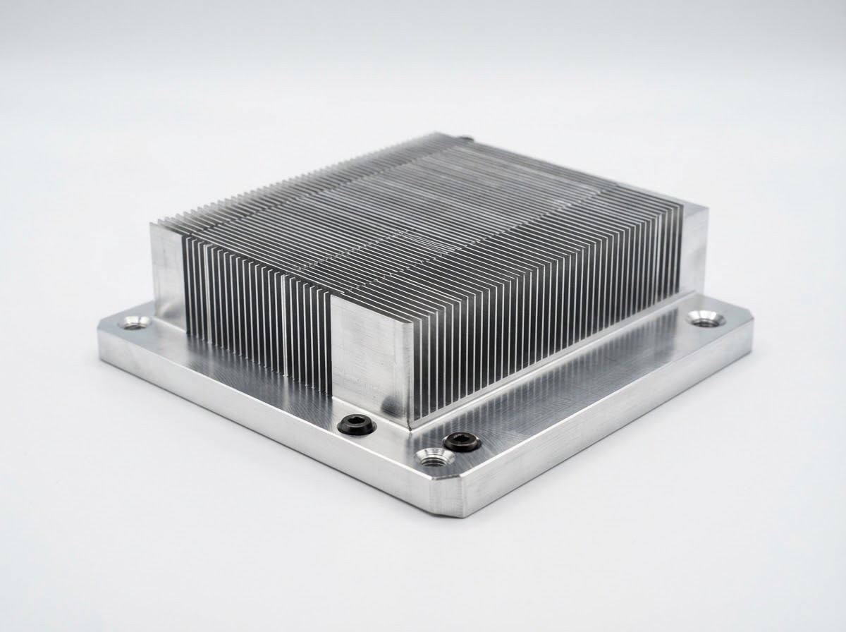
Precision Heat Sinks
CNC-machined and skived structures place the contact face and fins where your electronics need them.
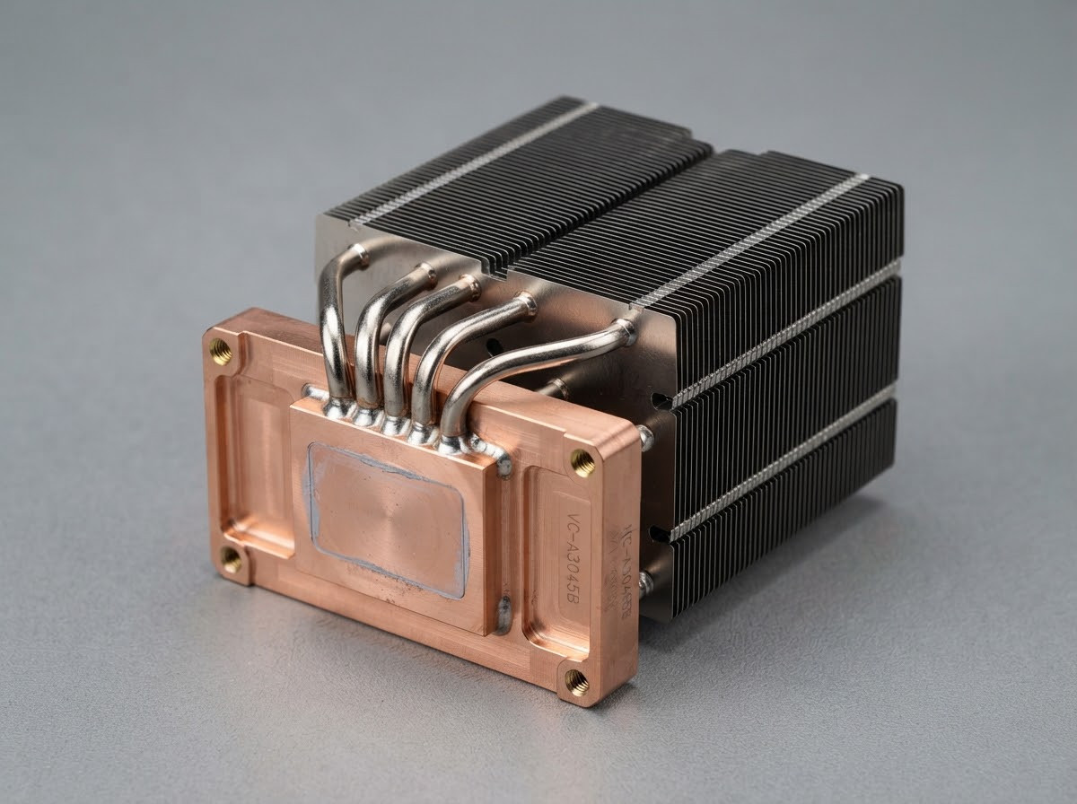
Heat Pipe & Vapor Chamber Assemblies
Spread concentrated heat or move it toward a larger fin area within the approved height, orientation and mounting limits.
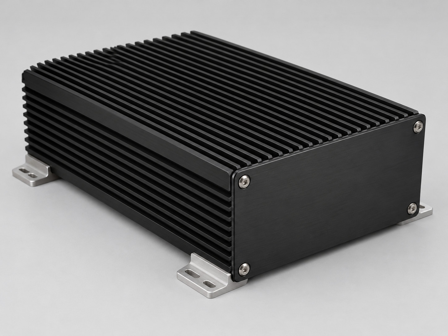
Thermal Enclosures
Combine the heat path, mounting features, and enclosure structure to support fanless industrial electronics.
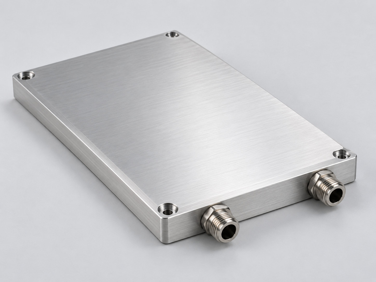
Liquid Cold Plates
Remove heat through a defined liquid path when local heat flux or enclosure limits make air cooling impractical.
Find the right balance of performance, fit, and production cost.
Compare Solutions for Your ProjectCooling Where Automation Happens
The same thermal principles need different mechanical answers across inspection, robotics, and industrial control.
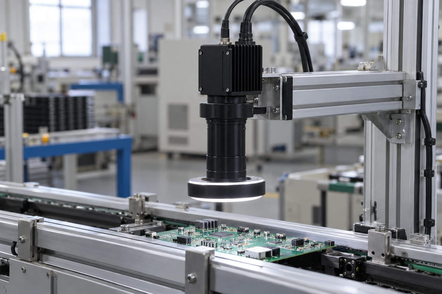
Inline Optical Inspection
Continuous image capture brings camera electronics and illumination close together.
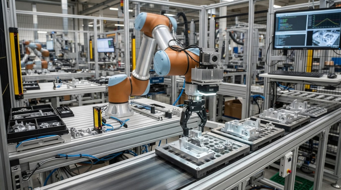
Robot Guidance & 3D Vision
Moving assemblies need compact cooling with controlled mass, mounting force, and cable clearance.
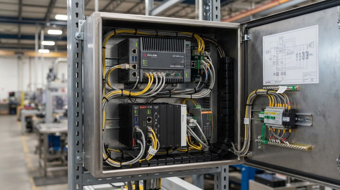
Vision Compute & Machine Control
Sustained processing and enclosed cabinets concentrate heat around CPUs, GPUs, and power stages.
Start with the way your equipment actually operates.
Discuss Your ApplicationEngineer the Complete Heat Path
A capable heat sink still needs the right interface, contact pressure, and route to the surrounding air or coolant.
From hotspot to heat rejection
ArchitectureChip or power device
TIM and controlled preload
Base, heat pipe, or vapor chamber
Fins to air OR cold plate to coolant
Make the thermal path part of the mechanical design.
Review Your Interface DrawingValidate Performance in Your Operating Conditions
Move from thermal requirements to repeatable acceptance criteria with drawings, measured conditions, and production records.
Define the boundary
Capture continuous and peak power, source size, ambient or inlet temperature, airflow or flow rate, and available space.
Review & develop
Compare manufacturing routes, review DFM and mounting, and use simulation where it helps resolve the design.
Build & measure
Test representative samples with defined sensors, installation, and steady-state criteria; record pressure drop for liquid cooling.
Freeze & reproduce
Release approved drawings, FAI and inspection criteria, batch traceability, and controlled engineering changes.
Give your engineering and procurement teams the same approval baseline.
Start an Engineering Review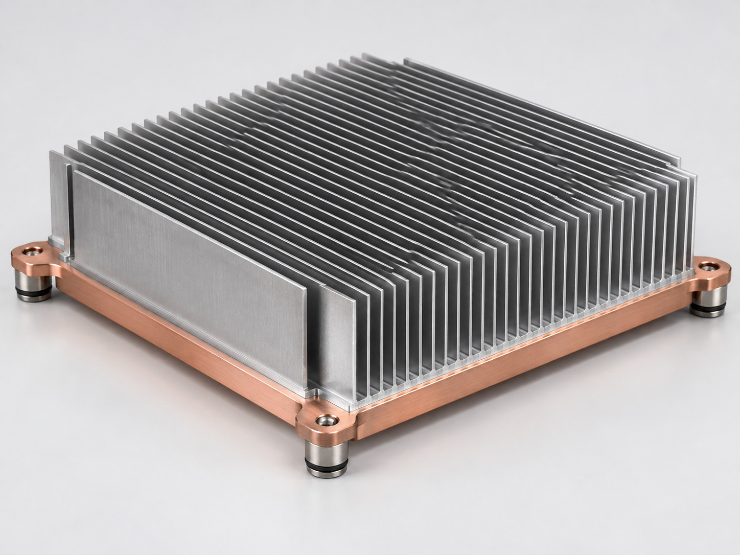
Hotspot Control for Industrial Image Processing
A low-profile vapor chamber assembly helped a Japanese equipment OEM spread a concentrated processor heat load.
Spread a 300 W load from a 20 × 20 mm source within a 150 × 150 × 45 mm assembly, while keeping the hotspot-to-outer-base temperature difference below 8 K.
A 3 mm copper vapor chamber, precision copper contact face, and aluminum fins, with support points, clamp load, and PCB clearance reviewed together.
The base hotspot reached 67 °C with an approximately 6 K difference to the outer base. Twenty engineering samples progressed to an initial 800-unit supply.
Test conditions: 25 °C inlet air, 160 m³/h airflow, 20 × 20 mm source, 150 × 150 × 45 mm assembly. Base-hotspot-to-inlet-air thermal resistance: 0.14 K/W.
See how a defined thermal boundary can guide your next design.
Discuss a Similar Thermal ChallengePractical Answers Before You Freeze the Design
Resolve the interface, validation, and supply questions that often hold up automation equipment development.
Can you cool a camera without adding a fan?
When is a vapor chamber useful?
When should we consider a liquid cold plate?
How do you protect sensitive boards during assembly?
What information is needed to start?
Can samples and production use the same specification?
Get the engineering questions answered before tooling and production.
Ask a Thermal Engineer
Let’s Engineer Your Next Automation Platform
Share your thermal challenge, installation envelope, and project stage. Morton will help turn them into a practical component and validation plan.