
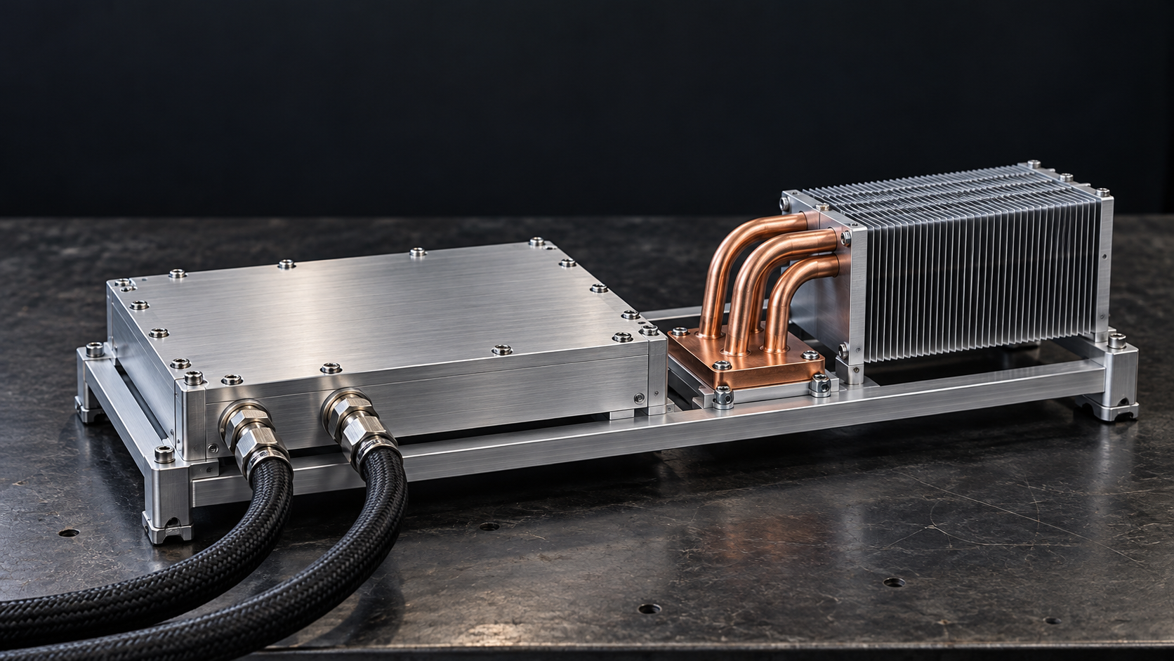
Hybrid Liquid-Cooled Heat Sinks
Liquid cooling for your primary heat load. Dedicated airflow for the components around it. One engineered assembly for demanding industrial equipment.
Two Cooling Paths. One Integrated Assembly
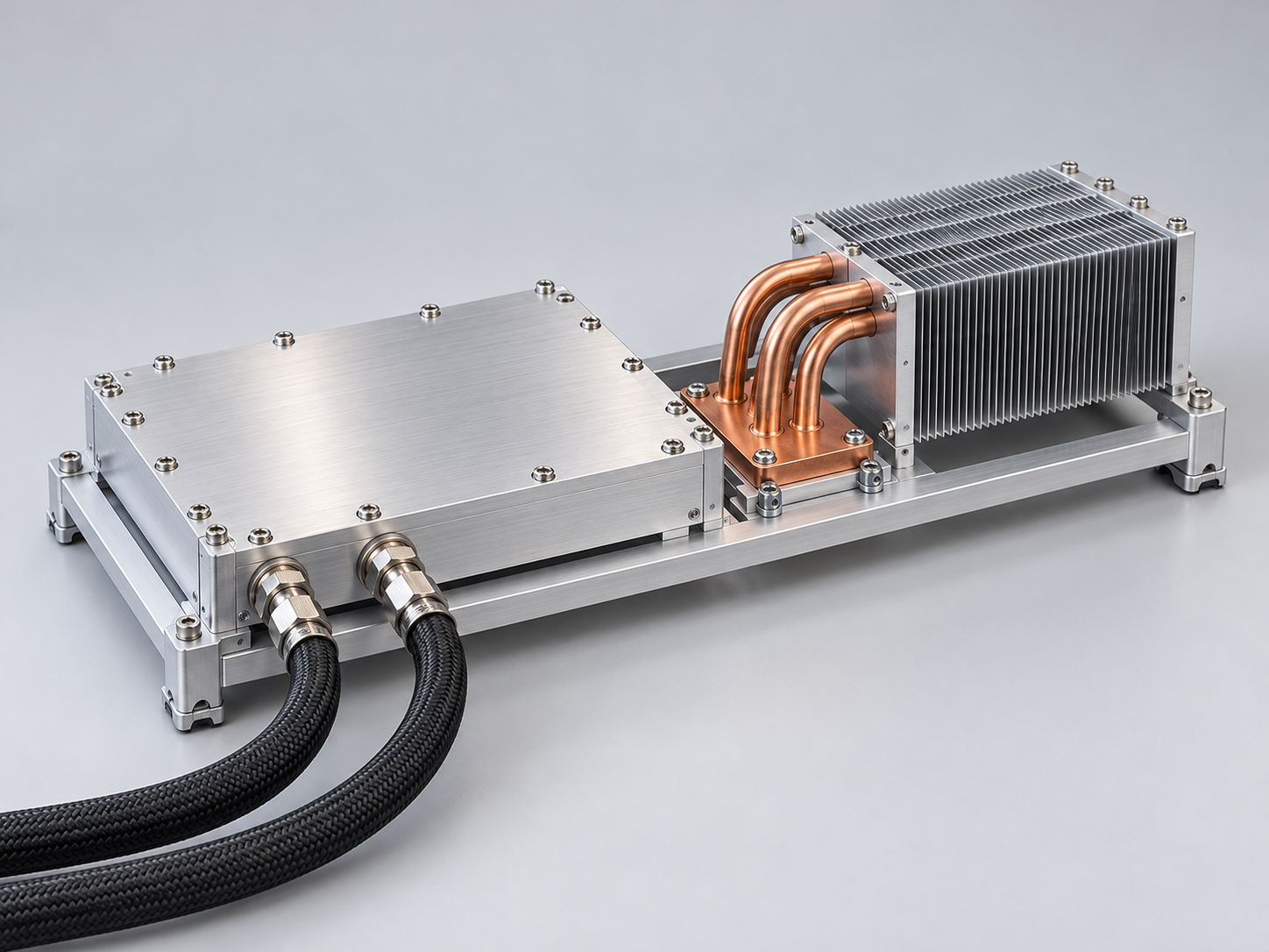
A hybrid heat sink combines a liquid-cooled base with a dedicated air-side heat exchanger, so each heat source has a cooling path that suits its load and location.
Liquid-cooled base
Moves concentrated heat into the coolant loop through a sealed, application-specific flow path.
Air-side cooling
Fins, heat pipes or a vapor chamber manage auxiliary heat within the available airflow.
Integrated interfaces
Coordinated mounting faces, ports and brackets simplify installation into your equipment.
Built Around the Heat Your System Actually Generates
Different components create different thermal demands. A coordinated hybrid layout helps you manage the full heat map within a practical mechanical envelope.
Concentrated main losses
Place the liquid-cooled contact zone directly under the high-power module to shorten its thermal path.
Distributed auxiliary heat
Use a separate air-side path for control boards, magnetics and secondary power devices.
Limited integration space
Coordinate the fins, ports and service clearances before the surrounding enclosure is frozen.
Share your component layout to identify the thermal bottlenecks early.
Map Your Heat SourcesFollow the Heat, from Device to Cooling Medium
Separate thermal paths let you evaluate the primary liquid loop and auxiliary airflow with the right boundary conditions for each.
The complete assembly is verified with the main and auxiliary loads applied together.
Turn your thermal boundaries into a clear, testable cooling concept.
Define Your Thermal PathsGive Every Thermal Zone the Space It Needs
A successful hybrid assembly coordinates contact surfaces, airflow and service access as carefully as the liquid circuit.
Dedicated contact zones
Match mounting heights and thermal interfaces to each device, reducing unnecessary shared thermal resistance.
Controlled airflow
Keep fins aligned with the installed air path and preserve inlet and outlet clearance.
Serviceable connections
Position coolant ports, fasteners and brackets so assembly and maintenance remain accessible.
Resolve interference and maintenance access before tooling begins.
Check Your Integration LayoutDefine Normal, Reduced-Flow and Standby Operation
Build operating limits around the actual duty cycle, then coordinate thermal interfaces with your equipment controls.
Normal operation
Reduced-flow operation
Standby / reduced-load cooling
Mounting provisions for temperature sensors and interlock interfaces can be integrated into the assembly.
Agree on operating limits that your engineering team can validate.
Set Your Operating EnvelopeA Practical Starting Point for Your Specification
Define the assembly around the heat map, coolant loop and installation envelope, then freeze the requirements in an approved drawing.
| Primary heat load | Power, heat-source footprint and device layout |
| Auxiliary heat load | Component losses, contact positions and permitted temperature |
| Liquid-side conditions | Coolant, inlet temperature, flow rate and allowable pressure drop |
| Air-side conditions | Inlet air temperature, installed airflow and duct resistance |
| Mechanical interfaces | Mounting pattern, contact flatness, port orientation and clearances |
| Operating modes | Normal load, reduced flow, standby duty and protection thresholds |
Overall size, fin density and interface tolerances are reviewed together for the selected manufacturing route.
Materials and Interfaces That Work as a System
Coordinate the base, fin assembly, thermal interface and wetted materials to support stable heat transfer and long-term integration.
Base and contact surfaces
Select aluminum or copper contact features to match heat spreading, strength, weight and machining needs.
Air-side connections
Specify the fin-to-base or heat-pipe connection method, then verify joint integrity and thermal consistency.
TIM and clamping
Control contact flatness, interface thickness, compression and fastener load to protect the device and the thermal path.
Coolant compatibility
Review all wetted metals, seals and coolant chemistry together. Select an inhibited coolant and validate the intended operating conditions.
For Equipment with More Than One Cooling Demand
Hybrid assemblies suit platforms where a concentrated main load and distributed auxiliary losses must coexist within one equipment architecture.
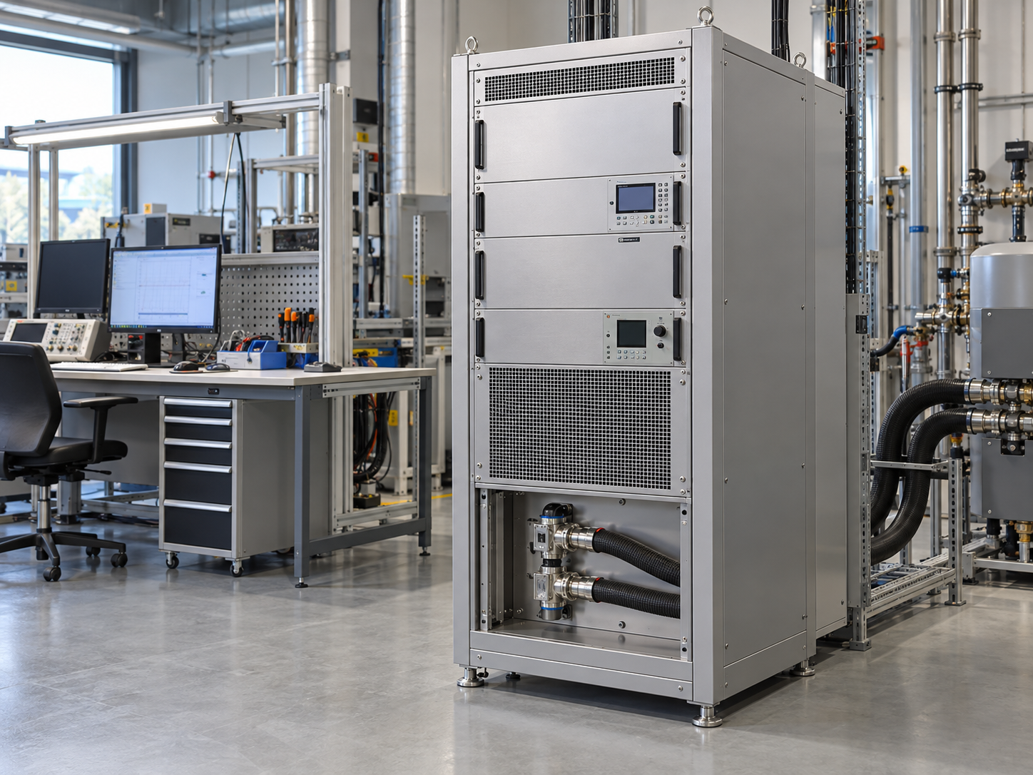
Power test equipment
Liquid cooling for high-power load stages, with air cooling for auxiliary control and supply components.
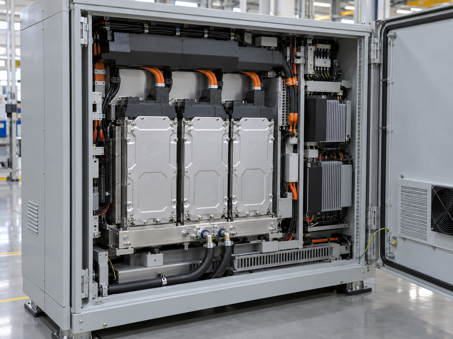
Industrial power conversion
Coordinate power modules, drivers and magnetics around separate thermal zones.
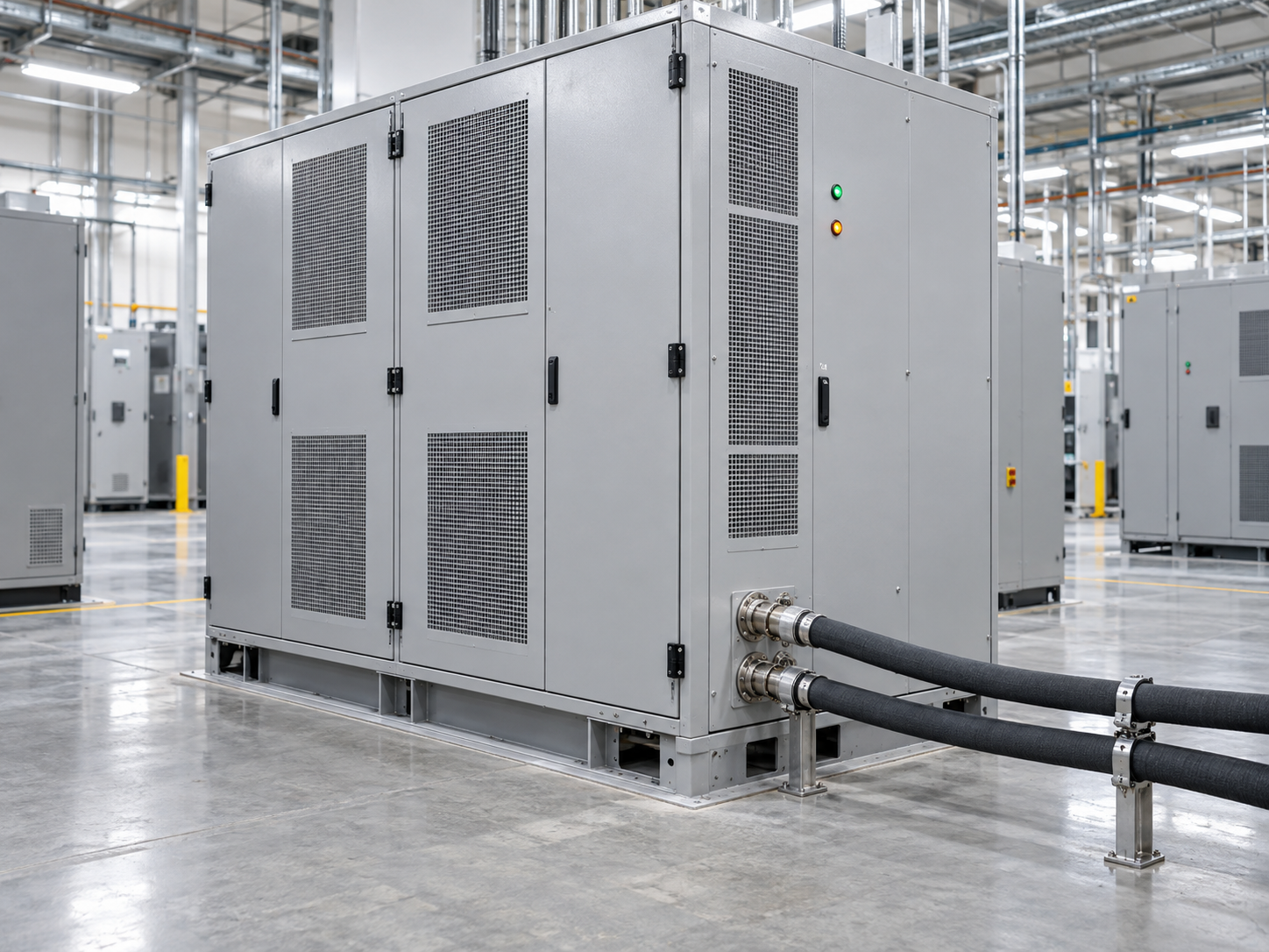
Energy storage PCS
Bring primary semiconductor cooling and auxiliary electronics into one serviceable mechanical layout.
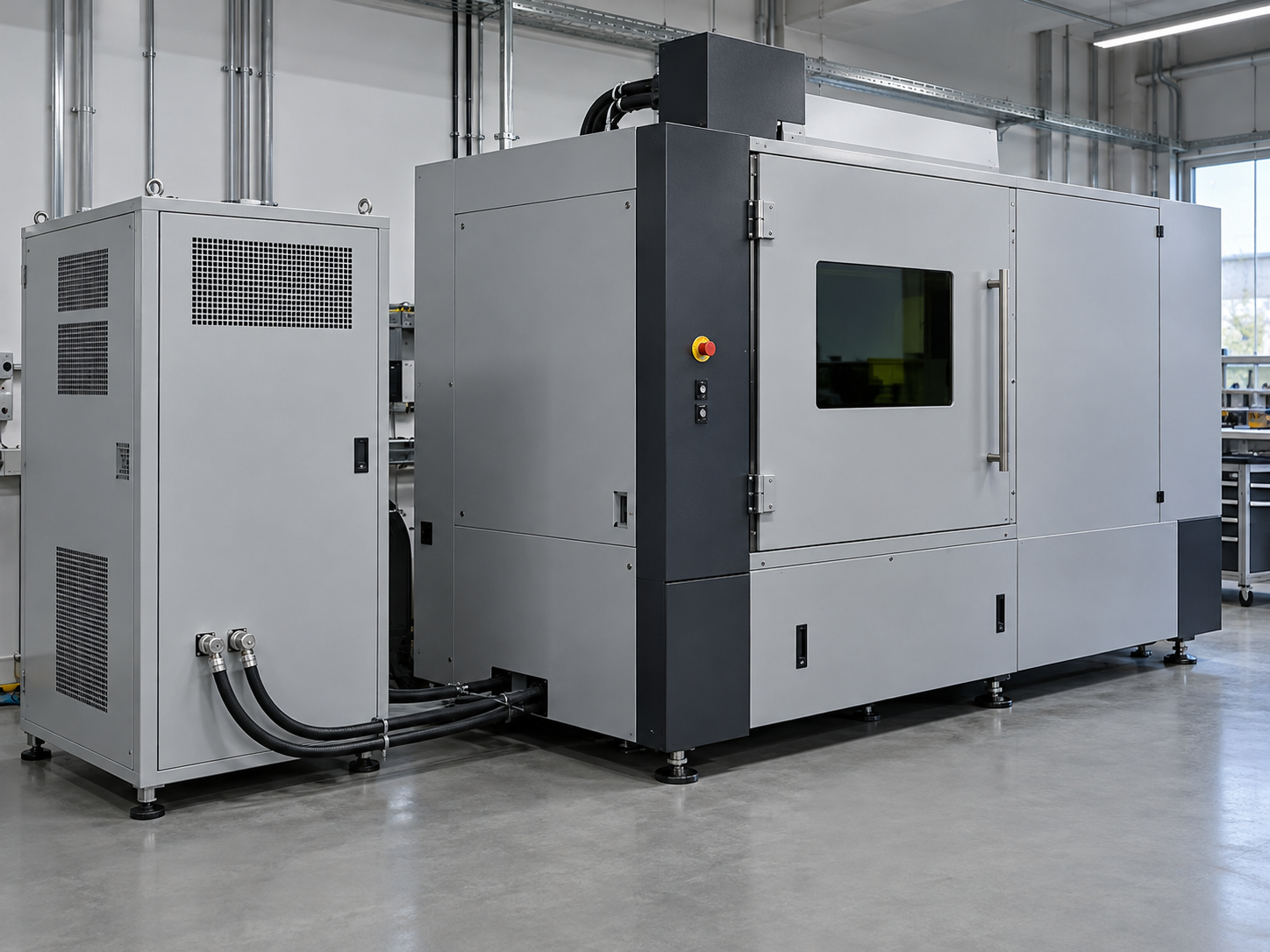
Laser and precision systems
Manage concentrated power-electronics losses alongside lower-power control devices.
Match the assembly to your equipment duty cycle and installation space.
Discuss Your ApplicationEngineered to Fit Your Platform
Customize the thermal and mechanical details that determine how the assembly installs, performs and scales into production.
- Contact heights, device footprints and mounting patterns
- Liquid flow path and port orientation
- Fin pitch, airflow direction and duct interfaces
- Heat-pipe or vapor-chamber integration
- Surface finish, masking and grounding features
- Brackets, TIM selection and assembly hardware
Thermal map
Component heat flux distribution, primary cold plate fluid boundary, and auxiliary airflow duct velocity vectors.
Mechanical drawing
Geometric dimensioning & tolerancing (GD&T), hydraulic port thread classes, mounting datum planes, and fin clearances.
Controlled BOM
Certified aluminum & copper alloys, wetted seal materials, fasteners, pre-applied interface materials, and inspection notes.
Supply can include the heat-exchange assembly, specified thermal interfaces and mounting hardware, with a coordinated drawing and BOM package.
Bring your CAD model into an engineering and manufacturability review.
Start a Custom Design ReviewValidate the Assembly, Not Just Its Individual Parts
Combine thermal, hydraulic and mechanical checks so your approved assembly is supported by clear test conditions and traceable records.
Simultaneous-load thermal test
Apply primary and auxiliary loads together. Record hotspot temperatures, inlet conditions, installed airflow, liquid flow and pressure drop.
Pressure and leak integrity
Set proof-pressure and gas-leak criteria for the approved pressure rating. Record test medium, stabilization time and acceptance limits.
Interfaces and assembly
Verify contact flatness, mounting dimensions, fastener condition, fin connections and specified clamping features.
Traceable release
Link the drawing revision, material batches, inspection results and test records to the delivered assembly.
Specify the evidence your engineering and quality teams need for approval.
Define Your Validation PlanA Hybrid Assembly for Dutch Power Test Equipment
One compact platform combined a liquid-cooled main power stage with an independent air-side path for auxiliary devices.
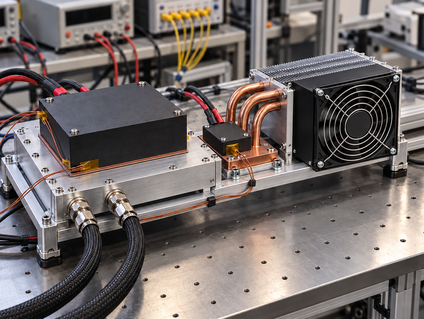
Assembly: 350 × 400 × 90 mm. Primary contact area: 100 × 100 mm. Inlet water: 30 °C at 8 L/min. Inlet air: 30 °C at an installed airflow of 90 m³/h. Main and auxiliary loads applied simultaneously.
The engineering solution
A friction stir welded liquid-cooled base handled the primary module. Independent fins and heat pipes cooled the auxiliary devices, with provisions for overtemperature interlocks.
The verified outcome
Primary thermal resistance was approximately 0.017 K/W relative to inlet water; auxiliary contact temperature was approximately 68 °C. A 20-unit pilot was followed by an initial 120-assembly delivery.
Reduced-flow operation was coordinated with equipment derating and interlock protection.
Use a comparable load map to start your own engineering discussion.
Discuss a Similar AssemblyMove from Thermal Requirements to Repeatable Supply
A single project team coordinates the requirements, design revision, prototype evidence and production release.
Requirements
Review heat map, cooling conditions, CAD and annual volume.
Concept & DFM
Align thermal paths, interfaces and manufacturing details.
Prototype
Build the agreed assembly and confirm key dimensions.
Validation
Review simultaneous-load tests and freeze acceptance criteria.
Production
Release the controlled BOM, inspection plan and delivery schedule.
Project timing starts from the agreed drawing, scope and commercial release conditions.
Set a realistic development route for your equipment launch.
Plan Your Prototype ScheduleQuestions Before You Start a Hybrid Cooling Project
Clarify the engineering inputs, operating limits and deliverables before your first design review.
When is a hybrid heat sink the right choice?
Can air cooling carry the full load if liquid flow stops?
What information do you need for an engineering review?
Can you provide the complete cooling system?
Which validation documents can accompany the assembly?
Can we start with a small engineering batch?
Get a focused answer based on your actual equipment conditions.
Ask an Engineering Question
Bring Your Hybrid Cooling Requirements to the Table
Share your heat loads, installation space and cooling conditions. Our team will help define a practical next step for your assembly.
- Primary and auxiliary loads reviewed together
- Custom contact zones, ports and mounting details
- Prototype and simultaneous-load validation support
- Controlled drawings, BOM and quality records
- A single team from concept to production