
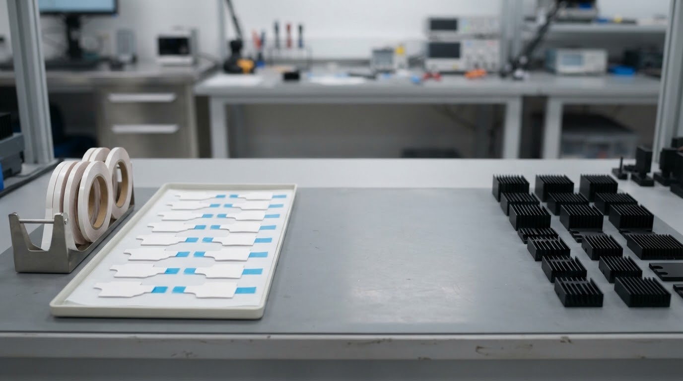
Thermal Tapes for Reliable Heat Sink Attachment
Combine heat transfer and adhesive mounting in one thin interface, with material selection and die-cut support for your lightweight thermal assemblies.
Start with your surface, footprint and operating conditions.
Discuss Your Tape Requirement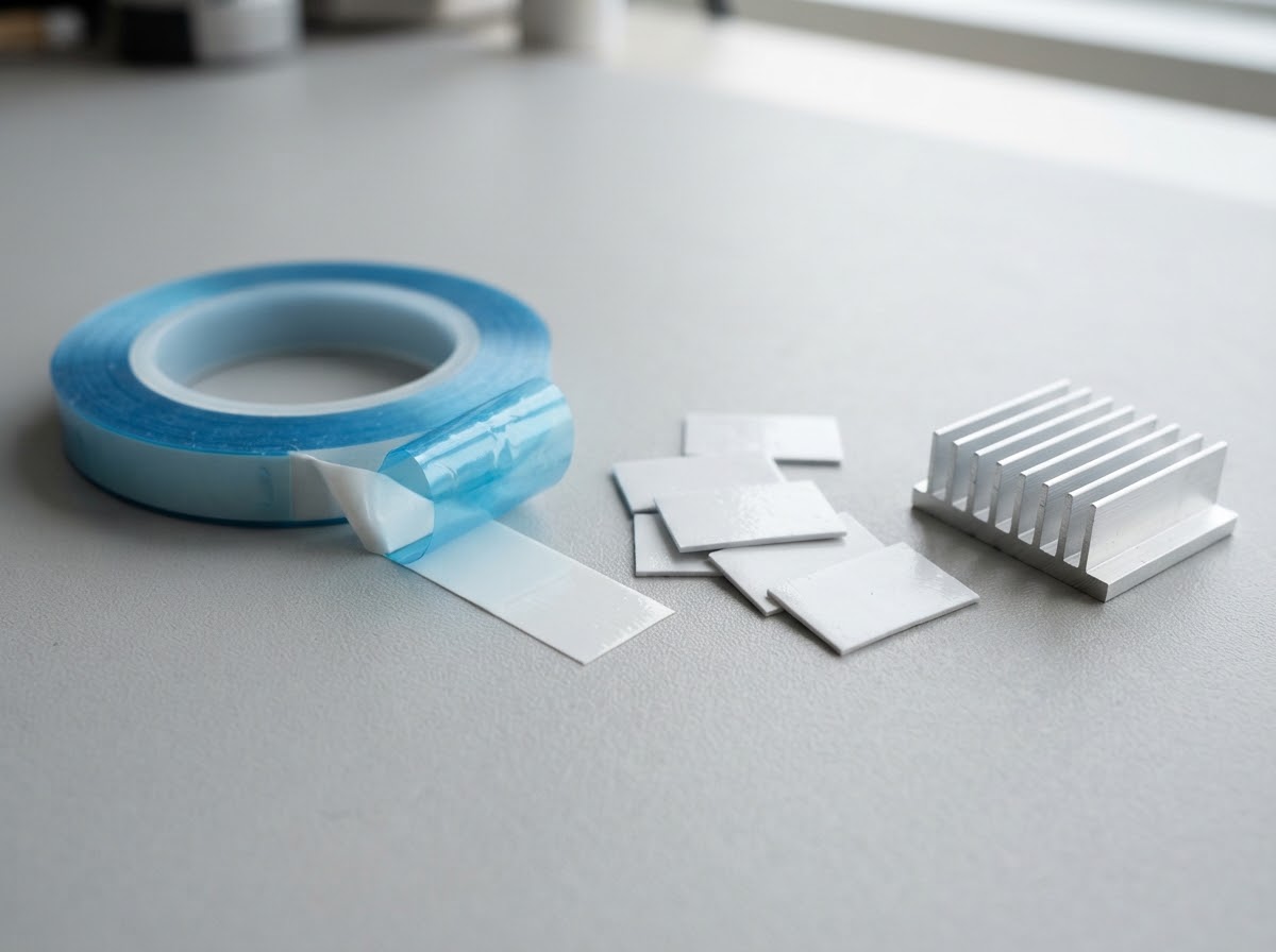
One Thin Interface. Two Essential Jobs
Thermal tape forms a conductive adhesive layer between a heat source and a lightweight heat sink, helping you simplify positioning and assembly.
Transfer heat across the interface
A thin, conformable bond line helps connect mating surfaces without a separate grease application.
Position and retain lightweight parts
Double-sided adhesion supports compact attachments where bond area, mass and operating loads are suitable.
Supply a part that fits your process
Choose a controlled material and cut outline, then add a practical liner and handling format.
Bring the thermal interface and assembly process into one discussion.
Review Your AssemblyHeat Transfer Starts at the Bond Line
Thickness, contact area and surface contact work together to determine the interface temperature rise.
Keep the layer thin
For a given material and area, a shorter conduction path reduces the bulk thermal resistance.
Use the available footprint
A larger bonded area supports heat flow and distributes mechanical load.
Control the contact
Clean mating faces and even application pressure help the adhesive wet the surfaces.
Share your contact footprint and thermal budget.
Review the Thermal PathChoose the Thickness Your Interface Needs
Select the tape as part of the assembly: balance thermal resistance, surface conformity and dimensional control.
0.6–2 W/(m·K)
0.1–0.5 mm
−20 to 120 °C
Rolls or die-cut parts
Start with the mating surfaces
Use the thinnest practical layer that can accommodate the approved surface condition and flatness.
Confirm the selected material
Conductivity, temperature rating, adhesion and electrical properties are tied to the chosen material specification.
Get a material recommendation around your actual interface.
Request Material SelectionTurn Contact Area into a Stronger Bond
A reliable attachment begins with the footprint and load direction, then follows through to the finished assembly.
Use a continuous footprint
Match the cut shape to the usable heat sink base, keeping adhesive clear of holes, edges and restricted areas.
Minimize peel and leverage
Keep the attached mass close to the interface and review cable forces, shock and installation orientation.
Verify the assembled joint
Evaluate holding performance after application dwell and the temperature exposure your product will see.
Match the Tape to Your Substrate
Material selection includes the surface finish and cleanliness of both sides of the joint.
Machined aluminum
Review roughness, flatness and residual machining fluid so the adhesive can make consistent contact.
Anodized aluminum
Confirm the coating condition and use representative finished samples for adhesion testing.
Copper contact faces
Control oxidation and handling contamination before bonding to the approved surface.
Component and coated surfaces
Check the package finish, coating adhesion and material compatibility using the actual production substrate.
Build Reliability around Your Real Loads
Adhesive performance depends on time, temperature and mechanical loading as well as initial tack.
Temperature exposure
Review continuous temperature, short peaks and the combined effect of heat and sustained load.
Static shear
Test the mounted mass in its working orientation, including the specified dwell and aging period.
Shock and vibration
Evaluate the complete assembly and add mechanical retention when the load case requires it.
Thermal cycling
Inspect bond integrity and thermal performance after cycling between the agreed temperature limits.
Describe the load case you need the joint to survive.
Discuss Reliability TestingDesigned for Lightweight Thermal Assemblies
Use thermal tape where a thin conductive adhesive joint matches the heat load, attachment mass and assembly method.
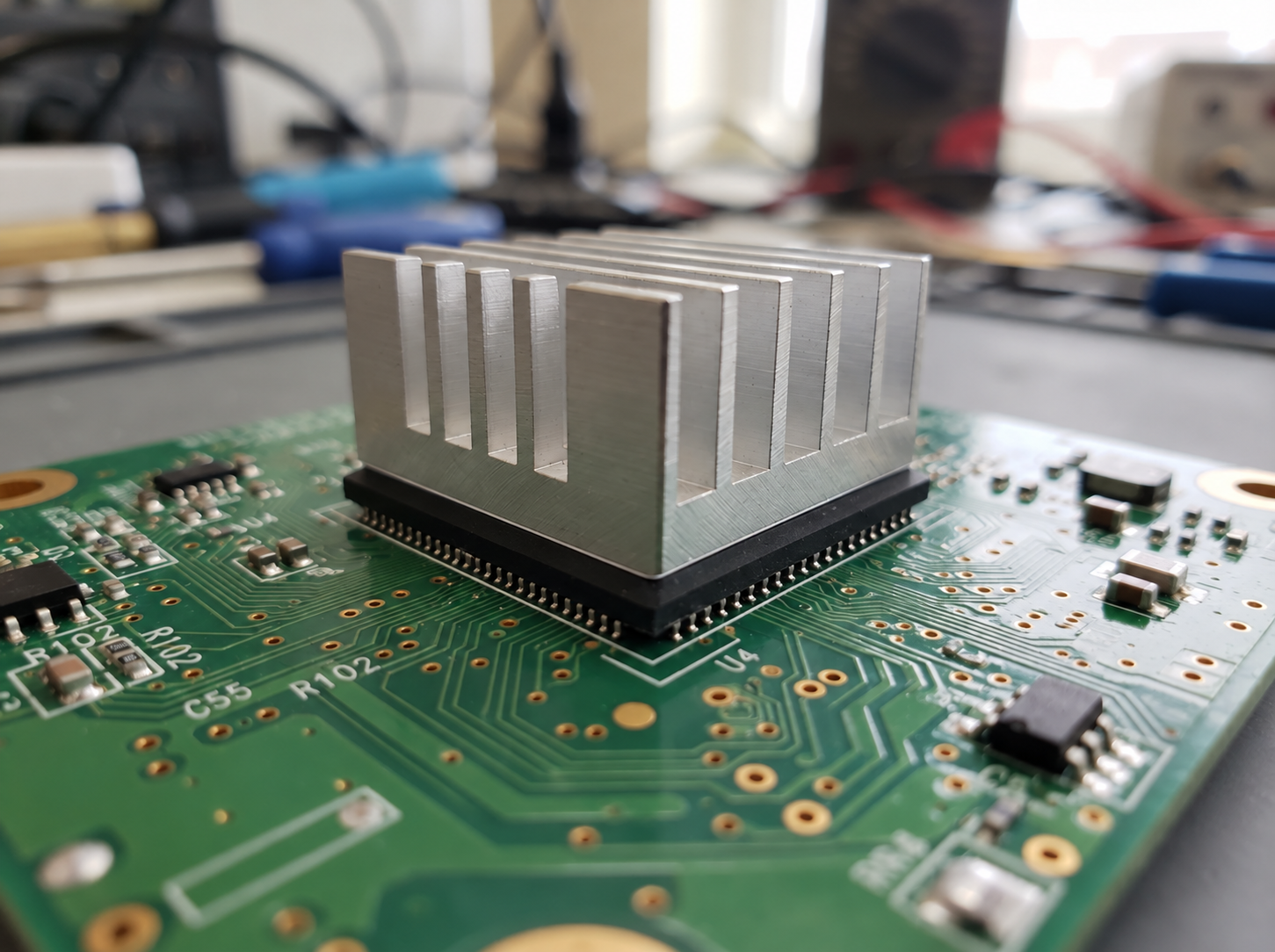
Board-level heat sinks
Attach compact aluminum heat sinks to suitable flat package surfaces after thermal and retention validation.

LED support assemblies
Bond lightweight LED boards to compatible aluminum surfaces with a controlled, continuous tape footprint.

Communication modules
Position small heat spreaders in compact electronic assemblies with accessible mating faces.

Industrial control electronics
Support repeatable heat sink attachment in low-mass control and interface modules.
Check whether tape suits your application and load case.
Review Your Application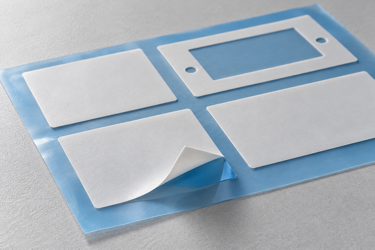
Die-Cut to Your Assembly, Ready for Your Line
A defined outline, practical liner and controlled packing format help operators place each tape part consistently.
Outline to drawing
Supply rectangles, shaped outlines and clearance cutouts against an approved cut drawing.
Handling that makes sense
Review liner tabs and peel access so operators can expose the adhesive without touching it.
A format for your workflow
Discuss individual pieces, sheets or a roll-fed format around handling and volume.
Clear part identification
Link material, drawing revision and batch labels to the approved supply specification.
Send your cut outline, liner preference and expected volume.
Discuss a Die-Cut PartA Repeatable Bonding Process
Turn the selected tape into a controlled assembly step with clean surfaces, consistent placement and a defined dwell.
01 · Prepare
Clean and dry both mating surfaces using a method compatible with the substrate.
02 · Position
Apply the tape without wrinkles, trapped contamination or contact with the adhesive.
03 · Press
Remove the remaining liner, align the parts and apply even pressure as specified for the material.
04 · Dwell and verify
Allow the agreed bond development period before loading, then check placement and retention.
Define an assembly sequence your production team can repeat.
Review the Bonding ProcessValidate Thermal Performance and Bond Strength
Evaluate the selected tape in a joint that represents your real surfaces, geometry and operating conditions.
Thermal interface performance
Record material, thickness, bonded area, heat load and temperatures to assess the interface temperature rise.
Peel and shear performance
Define substrate finish, application pressure, dwell, load direction and test temperature for meaningful comparisons.
Aging and assembly integrity
Review retention and thermal behavior after the agreed heat exposure, humidity or temperature cycling.
Build the acceptance plan around the way your product is used.
Plan Your ValidationDocumentation That Follows Every Tape Batch
Connect the selected material and cut part to the information your engineering, purchasing and quality teams need.
Material definition
A material data sheet and the agreed thermal, adhesive and storage requirements identify what is approved.
Part and batch control
A controlled cut drawing, material reference and batch identification help keep repeat deliveries consistent.
Project documentation
Request material conformity information, inspection records and change control matched to the order requirements.
Tell us which documents your supplier approval process requires.
Request a Documentation ReviewFrom Sample Fit to Repeat Supply
Move from interface review to an approved tape part, then keep the same material and drawing controls in repeat orders.
Review the requirement
Share surfaces, contact area, heat load, operating temperature and the attached mass.
Select and sample
Confirm a candidate material, cut geometry and liner format for fit and process trials.
Approve the joint
Validate thermal performance and retention, then freeze the material and cut drawing.
Repeat with control
Order against the approved part definition with batch identification and agreed packing.
Start with a sample plan and a clear route to repeat orders.
Start a Tape ProjectAnswers Before You Specify Thermal Tape
Resolve the practical questions that affect material choice, mounting reliability and production handling.
Can thermal tape replace screws or clips?
Is thermal tape the same as a gap pad?
How do I choose the thickness?
Is every material electrically insulating?
Can you provide custom die-cut shapes?
What should I send for a quotation?
Have a question specific to your assembly?
Ask an Engineer
Let’s Define Your Thermal Tape
Tell us how your parts meet, what they need to transfer and how they will be assembled. We’ll help you define the next step.