

Heat Pipe Cooling Assembly for Telecom Power Equipment
How Morton moved 450 W from a concentrated hotspot into a larger fin field—within an 80 mm height limit and with the existing system fan.
The Project, Defined by Its Operating Conditions
A Singapore telecom power OEM needed to spread concentrated device losses across the available fin area while preserving the equipment envelope and installed airflow.
- Effective thermal load
- 450 W
- Heat-source footprint
- 60 × 60 mm
- Assembly envelope
- 200 × 250 × 80 mm
- Inlet air temperature
- 25°C
- Installed airflow
- 220 m³/h
- Cooling architecture
- Heat pipes + aluminum zipper fins
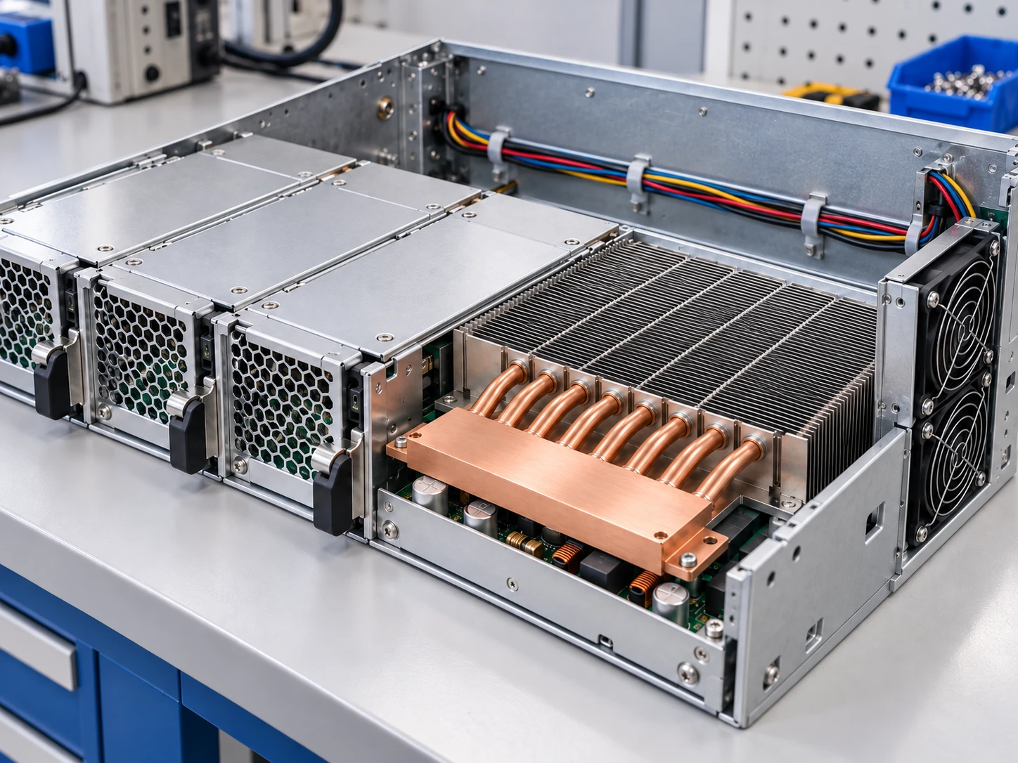
A Small Hotspot Needed More of the Fin Field
Adding metal alone would not resolve an offset heat source. The design had to improve heat distribution without consuming extra height or relying on a larger fan.
Concentrated heat input
A 60 × 60 mm source had to use a much larger 200 × 250 mm fin region. The thermal path needed to reach the available surface area.
A fixed height budget
The contact block, formed pipes, fin pack and mounting features had to fit together inside the 80 mm assembly height.
An existing airflow system
Fin spacing and flow direction had to match the installed fan operating point rather than its unrestricted free-air rating.
A clear set of constraints makes the right cooling architecture easier to select.
Define My Thermal Design Brief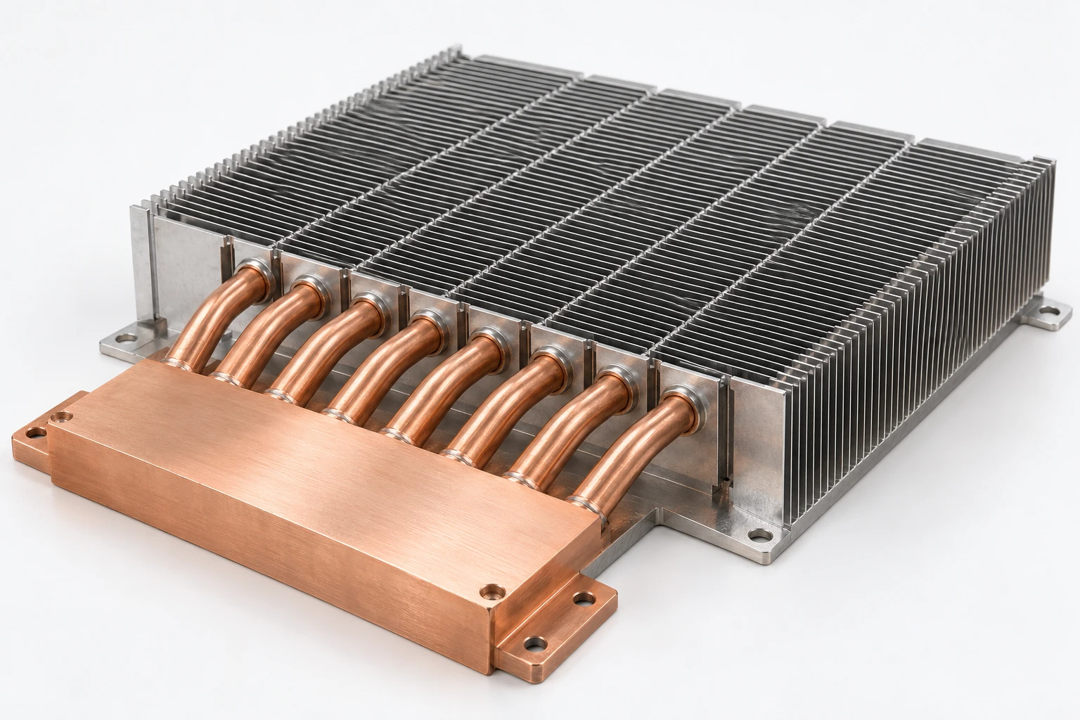
The Assembly That Connected Hotspot to Airflow
Eight copper–water heat pipes link a copper contact block to an aluminum zipper-fin array, distributing heat into the fin field available to the system airflow.
Copper contact block
Collects heat from the defined source footprint and provides a controlled mounting interface.
8 × Ø8 mm heat pipes
Carry heat into the fin array with routing matched to the source position and permitted installation attitudes.
Aluminum zipper-fin array
Provides a repeatable fin pitch and broad air-side surface within the package boundary.
Build the heat path around your source layout and enclosure.
Request a Custom Heat Pipe AssemblyFour Design Decisions Built One Continuous Heat Path
The useful result came from the complete thermal path: interface contact, two-phase transport, fin coupling and air-side rejection working together.
Collect
A defined copper contact surface receives heat from the 60 × 60 mm source.
Transport
Sealed copper–water heat pipes move heat from the evaporator region toward the fin field.
Distribute
The condenser coverage and pipe-to-fin joints spread heat into more of the aluminum fins.
Reject
Aligned fin channels pass heat into the measured 220 m³/h system airflow.
Horizontal and permitted inclined attitudes were checked; performance is tied to the approved installation configuration.
Fin spacing is selected with the installed fan and ducting so useful surface area remains accessible to airflow.
Engineered to Fit the Platform and Its Assembly Process
Thermal performance was developed alongside package clearance, contact force, pipe routing and manufacturing control so the approved sample could become a repeatable assembly.
Source
Package and keep-outs
Align the contact block, fin pack and formed pipes with the equipment mounting and clearance boundaries.
Controlled mounting force
Define installation force and interface contact so the source is coupled without overloading the device.
Pipe routing and attitude
Freeze the pipe geometry and approved assembly orientation in the released drawing package.
Protected handling
Use fin-protection packaging and assembly instructions to preserve the approved geometry through delivery.
Validation Conditions You Can Reproduce
The reported result is tied to a defined heat input, inlet condition, installed airflow and assembly attitude—not an isolated heat-sink number.
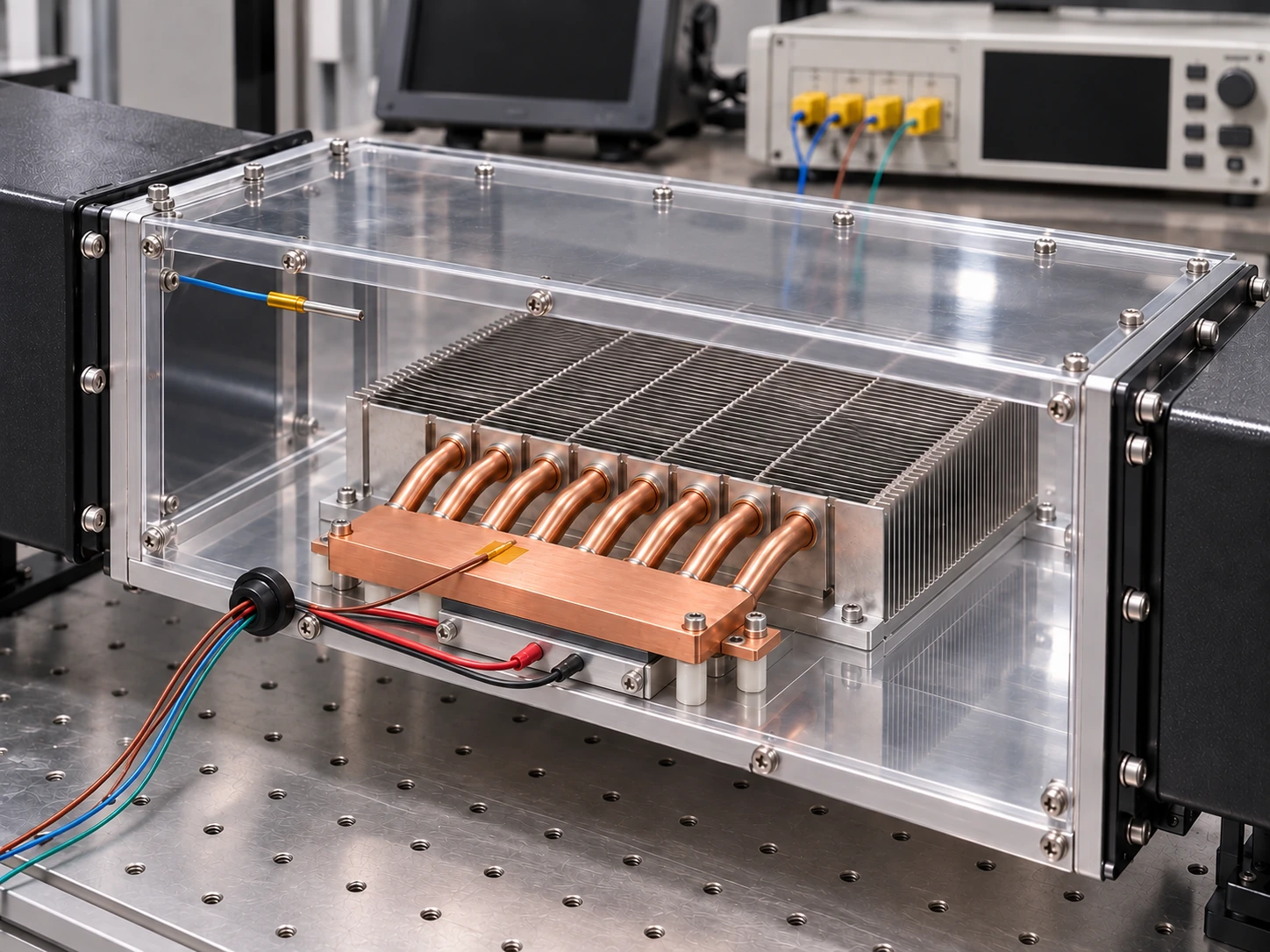
| Effective heat input | 450 W at a 60 × 60 mm source |
|---|---|
| Inlet air | 25°C |
| Installed airflow | 220 m³/h through the fin field |
| Measurement reference | Base hotspot relative to inlet air |
| Installation | Design attitude; horizontal and permitted inclinations reviewed |
| Reported steady-state result | 69.1°C hotspot · 0.098 K/W |
Vibration screening
Assembly samples passed the prescribed vibration screening.
Temperature cycling
Assembly samples passed the specified −20°C to 80°C thermal-cycle screening.
A Measured Thermal Result, with a Clear Reference
At 450 W, 25°C inlet air and 220 m³/h installed flow, the assembly reached a 69.1°C base hotspot in its design installation attitude.
The reference is the base hotspot
Device junction temperature requires the device-internal and interface temperature rises in addition to this assembly result.
The equipment fan stayed in place
Heat spreading addressed the offset source without changing the system fan.
From Approved Samples to a Controlled First Build
The project moved from sample development to approval in seven weeks, followed by a first delivery of 500 assemblies supported by controlled build documentation.
Define
Freeze heat load, geometry and airflow boundaries.
Develop
Coordinate contact block, heat pipes and zipper fins.
Validate
Review thermal results and prescribed screening.
Release
Lock approved drawings and production controls.
Tell Us Where Your Heat Has to Go
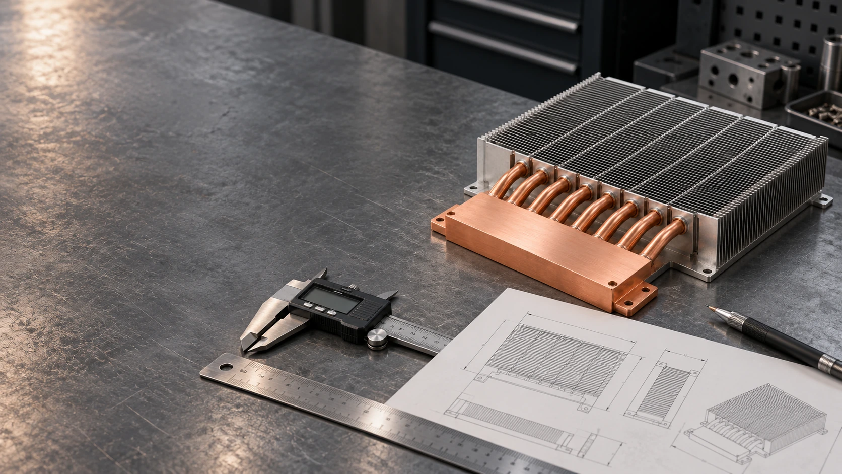
Share your source layout, allowable temperature, installed airflow and package limits. Morton will help you evaluate a practical path from concept to a repeatable cooling assembly.
Start a Thermal Design Review
A few project details are enough to begin the conversation.