
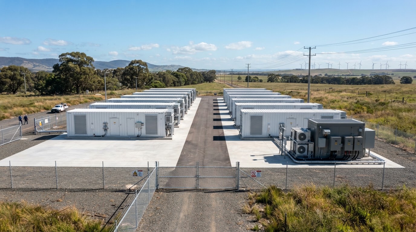
Thermal Management for Energy Storage Systems
Custom cold plates, PCS heat sinks and thermal interfaces engineered around your heat load, site conditions and production needs.
When Heat Becomes a System Constraint
Temperature variation and PCS overheating can limit usable energy, charge/discharge power and availability. Define cooling limits at the module and converter interfaces before system integration.
Uneven module temperatures
Temperature gradients can accelerate uneven cell aging and constrain pack operation around the hottest or most degraded cells.
PCS derating under load
Concentrated semiconductor losses consume thermal headroom when ambient and coolant temperatures rise.
Leakage and corrosion risks
Incompatible wetted materials, trapped air and poorly defined interfaces create avoidable maintenance exposure.
Late integration changes
Unclear flow, mounting and test requirements lead to repeated prototypes and delayed project milestones.
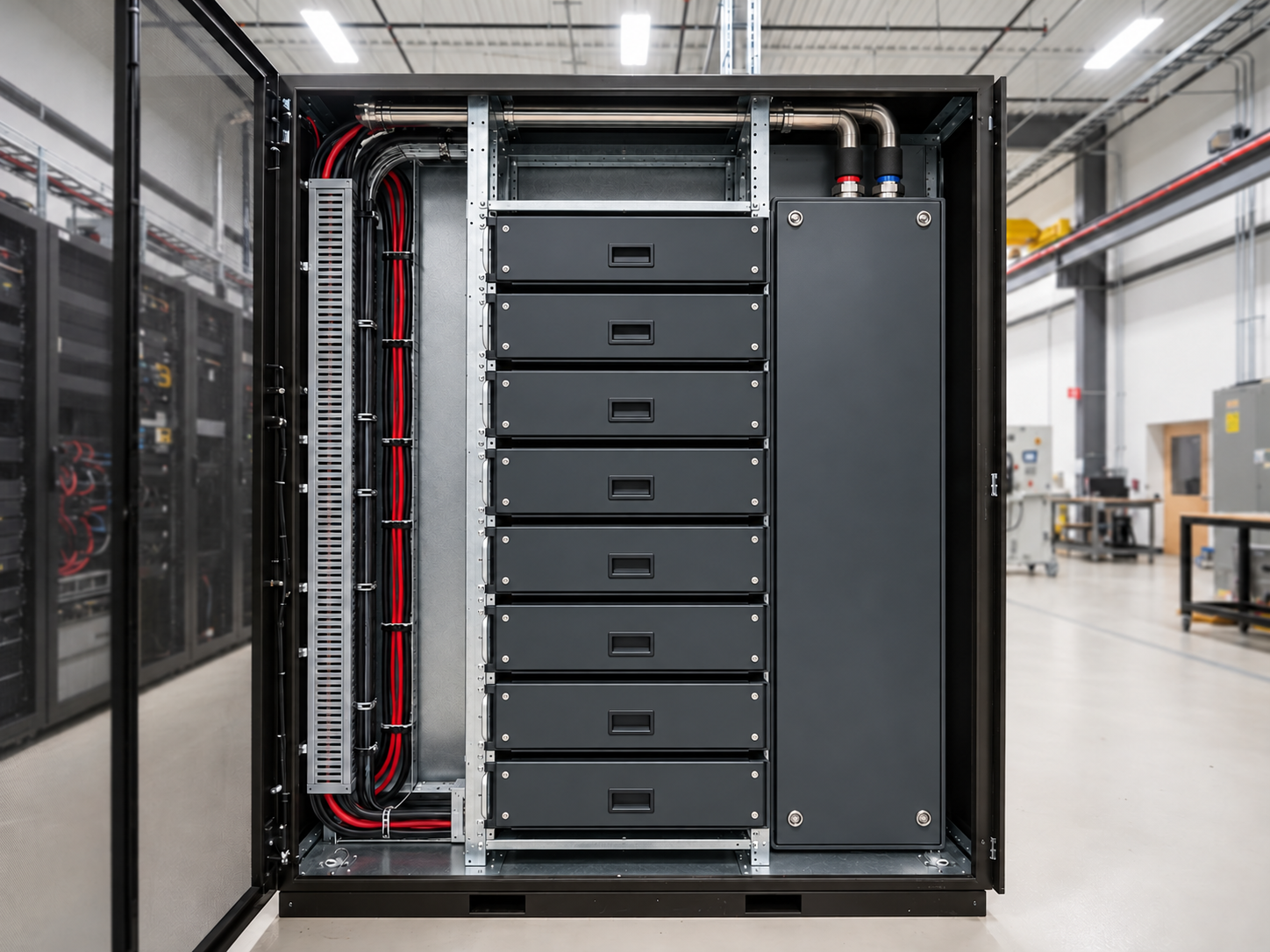
Cooling components matched to the battery, conversion and control zones.
Follow the Heat Through Your ESS
Battery modules, PCS stages and controls have different temperature limits and heat paths. Define each interface so one subsystem does not constrain the platform.
Battery modules
Engineered cold plates distribute contact cooling across the approved module footprint. Channel layout, mounting and TIM compression are reviewed together.
PCS and DC/DC stages
Liquid cold plates or air-cooled heat sinks remove concentrated IGBT and SiC losses within the available flow or airflow budget.
Controls and auxiliary electronics
Compact heat sinks, thermal enclosures and interface materials complete the lower-power thermal paths.
Define the thermal path before freezing the mechanical layout.
Map Your Heat SourcesCooling Components Matched to the Job
Every thermal architecture balances cooling medium, pressure allowance, and mechanical tolerances. We fabricate targeted components tailored to your system boundary limits.
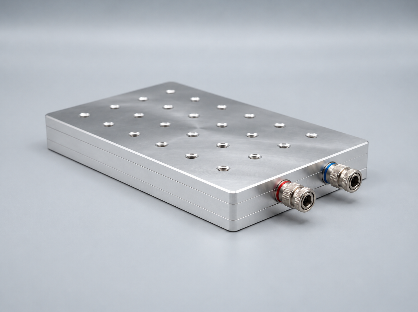
Liquid cold plates
Tube-in-plate, vacuum-brazed, friction-stir-welded and microchannel structures provide direct conductive cooling for battery modules and PCS power devices.
- Channel geometry matched to heat distribution
- Ports coordinated with the coolant loop
- Flat contact faces and controlled sealing
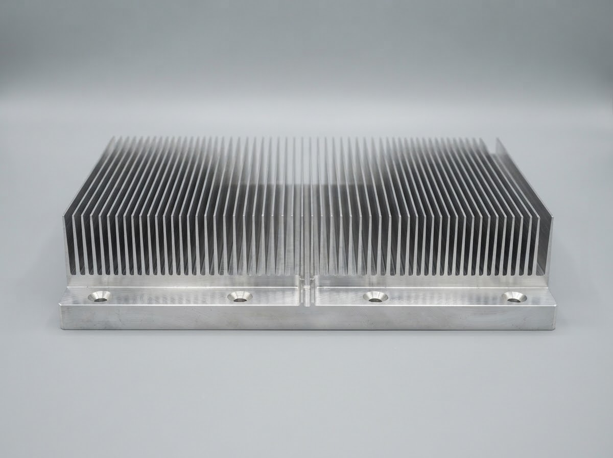
PCS heat sinks
Extruded, skived and bonded-fin structures use the installed airflow effectively for power conversion stages that favor an air-cooled architecture.
- Fin spacing matched to the fan working point
- Machined semiconductor mounting faces
- Practical access for assembly and cleaning
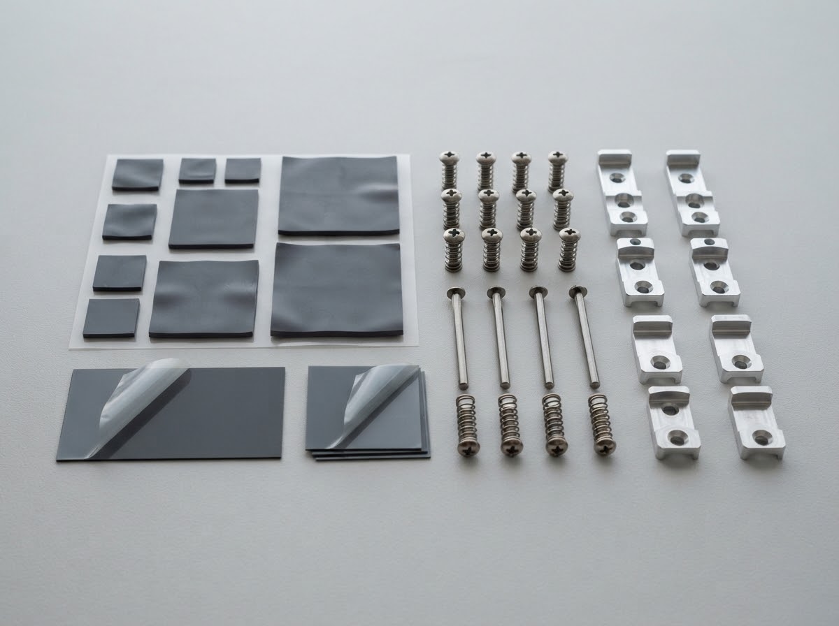
Thermal interfaces and mounting
Die-cut pads, spring fasteners and brackets help maintain the intended contact path through assembly tolerances and service cycles.
- Gap and compression matched to the stack
- Device load limits considered
- Controlled positioning and fastening
Build a cooling package around your approved platform.
Select Your Cooling RouteA Design Envelope You Can Engineer Against
Engineering an ESS thermal architecture requires rigorous alignment across heat loads, fluid circuits, and mechanical constraints before freezing specifications.
| Design input | What we define |
|---|---|
|
Heat load and footprint
|
Losses across charge/discharge and PCS duty cycles, source layout, maximum cell or device contact temperature, and allowed temperature spread across the battery module. |
|
Fluid circuit
|
Coolant formulation, inlet temperature, flow rate and cold-plate pressure drop. |
|
Mechanical integration
|
Envelope, contact-face flatness, mounting pattern, port orientation and service access. |
|
Installed airflow
|
Actual flow through the heat sink, air pressure drop, fan curve and inlet-air temperature. |
|
Acceptance conditions
|
Measurement positions, steady-state criteria, drawing revision and agreed test limits. |
Share the boundary conditions that matter to your design.
Define Your Cooling SpecificationDesigned Around the Site, Not Just the Bench
Real-world ESS deployments expose cooling hardware to harsh ambient profiles, diverse fluid chemistries, and strict enclosure constraints that lab benches rarely replicate.
High ambient operation
Review the inlet-air and inlet-coolant temperatures expected at the site, including the equipment derating strategy.
Coolant compatibility
Coordinate aluminum, copper, stainless steel, seals and the inhibited coolant formulation to manage corrosion risks.
Flow and cleanliness
Check pump working point, trapped-air removal, channel cleanliness and filtration against the smallest passages.
Outdoor integration
Consider condensation, surface protection, connection access and the system-level enclosure requirements.
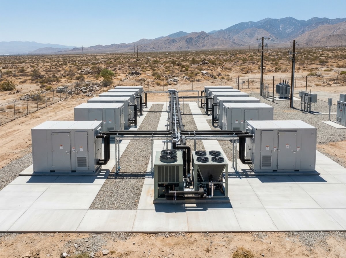
Make the field conditions part of the first design review.
Review Your Operating EnvironmentA PCS Cooling Challenge, Made Measurable
Defined prototype tests give engineering and procurement a shared basis for comparing cold-plate performance before tooling commitment.
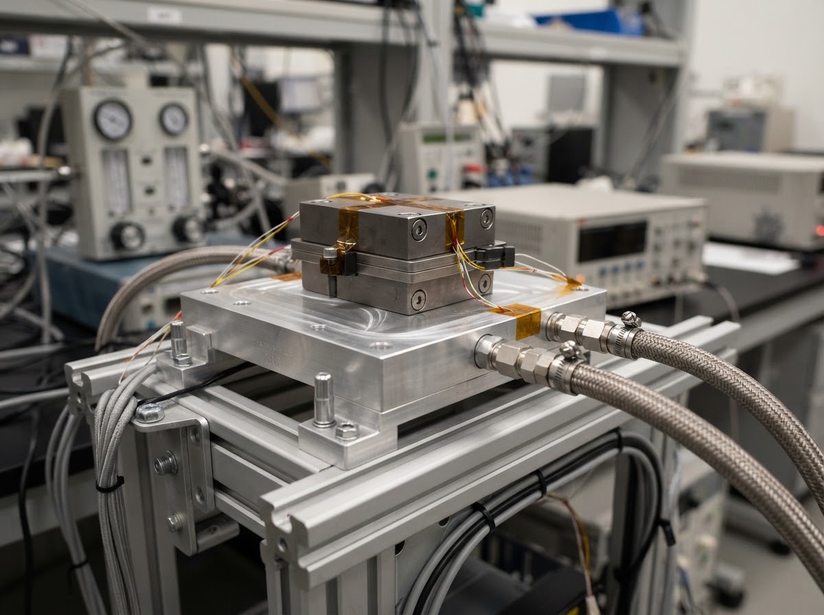
Test conditions: 25 °C inlet water at 10 L/min; 1,000 W applied heat load. Pressure drop measured at the cold-plate ports.
Field operating point: Qualify the specified 40 °C inlet and inhibited water-glycol coolant as a separate operating point; the water-test result does not establish field performance.
From Prototype to Repeatable Supply
A disciplined four-stage engineering and quality route from initial DFM through full production traceability.
Define and review
Freeze the heat sources, operating limits, interfaces and drawing revision through DFM and thermal review.
Build and correlate
Produce engineering samples and compare simulation with thermal and pressure-drop measurements.
Verify and release
Check critical dimensions, contact faces, cleanliness and the approved pressure and leak-test requirements.
Control and deliver
Link material batches, work orders, inspection results and packing labels; approve changes before implementation.
Engineering Questions, Answered
Direct technical clarification on cooling medium selection, interface boundaries, qualification testing, and production supply.
When should an ESS use liquid cooling rather than air cooling?
Can you support battery cold plates as well as PCS cooling?
What information is needed for a first review?
Can a 25 °C water test predict hot-climate glycol performance?
How are coolant leakage and material compatibility addressed?
Can you supply samples before series production?
Bring the remaining questions to an engineering review.
Ask About Your ESS Cooling Design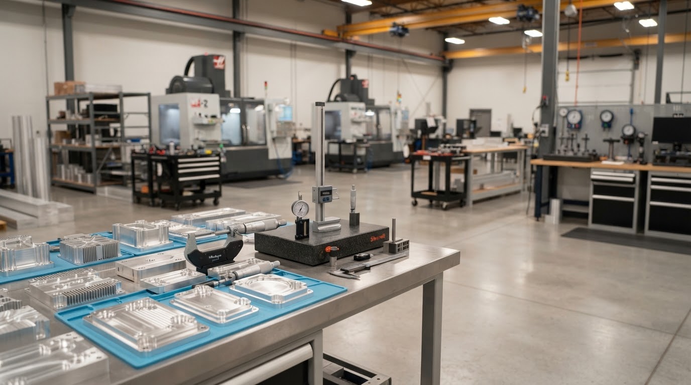
Bring Your ESS Cooling Requirements to the Table
Engage our thermal engineering team directly with your boundary conditions, module heat dissipation budgets, and packaging constraints.
Tell Us About Your Project
Start with the essentials. Detailed drawings can follow during the engineering review.