
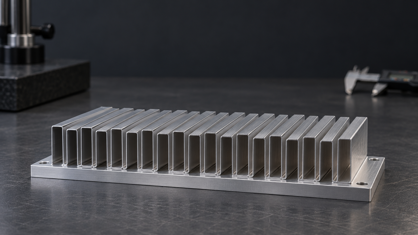
Folded Fin Heat Sinks for Compact Airflow Paths
Thin aluminum or copper strip, precisely folded and joined to a custom base. Morton helps you balance cooling area, pressure drop, weight, and assembly fit.
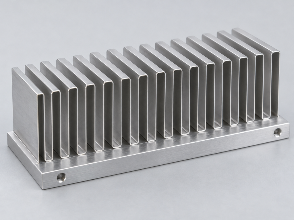
What Is a Folded Fin Heat Sink?
A continuous metal strip forms a repeating corrugated fin core. Joining the core to a heat-spreading base creates a compact path from the heat source to the moving air.
Connected crests and valleys keep the fin geometry consistent across the core.
Brazing, soldering, or thermal adhesive transfers heat into the folded fins.
Open passages guide air through the active surface instead of around the assembly.
More Cooling Surface. Less Structural Weight
Thin, closely controlled fins put material where it contributes to heat exchange, helping compact equipment use its available airflow more effectively.
High surface density
Thin strip creates substantial exposed area inside a compact fin volume.
Lower fin mass
Use lightweight foil construction where system weight and handling matter.
Flexible fin geometry
Tune pitch, height, and core length around the enclosure and fan.
Base material choices
Match spreading performance, mass, and joining requirements.
Assembly-ready interfaces
Coordinate mounting holes, keep-out zones, and thermal contact surfaces.
Scalable repeatability
Freeze the forming and joining process before repeat production.
Turn your space and weight constraints into a practical fin specification.
Explore a Custom Fin CoreFin Geometry That Fits Your Air Path
Choose foil thickness, pitch, and fin height together. Each dimension affects forming stability, pressure drop, fin efficiency, and handling strength.
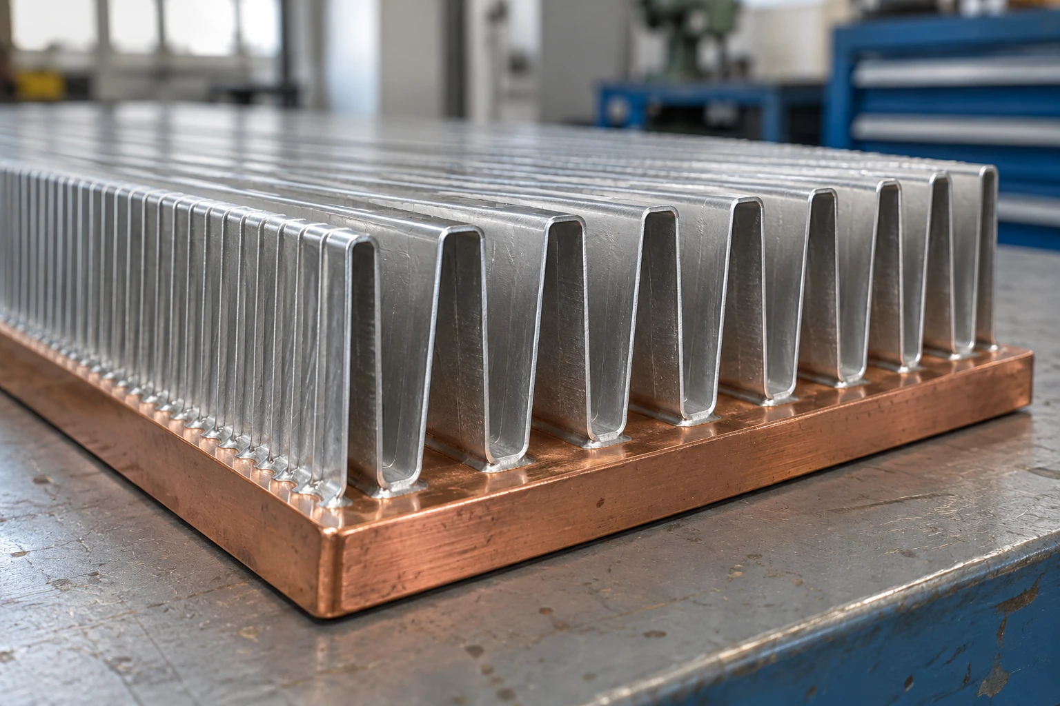
Geometry is developed as a complete assembly: strip thickness, bend radius, joining area, and passage size are reviewed together.
Share your space limits and let us evaluate a manufacturable geometry.
Check Fin GeometryAluminum or Copper, Selected for the Assembly
Material selection starts with heat spreading, mass, joining compatibility, and the environment in which your equipment operates.
Aluminum folded fins
A low-mass choice for ducted cooling and weight-sensitive equipment. Coordinate the strip alloy, temper, and base with the selected brazing or bonding process.
- Low assembly mass
- Formability matched to the fold
- Surface finish and masking defined
Copper folded fins
High conductivity supports compact heat paths and demanding local heat spreading. Evaluate the added mass, soldering process, and compatibility with the base.
- High material conductivity
- Solderable material combinations
- Corrosion and coating reviewed
Compare material combinations against your thermal and mechanical priorities.
Discuss Material SelectionThe Fin-to-Base Joint Is Part of the Thermal Design
A repeatable connection transfers heat into the folded core and holds the geometry through assembly and service.
Brazed assembly
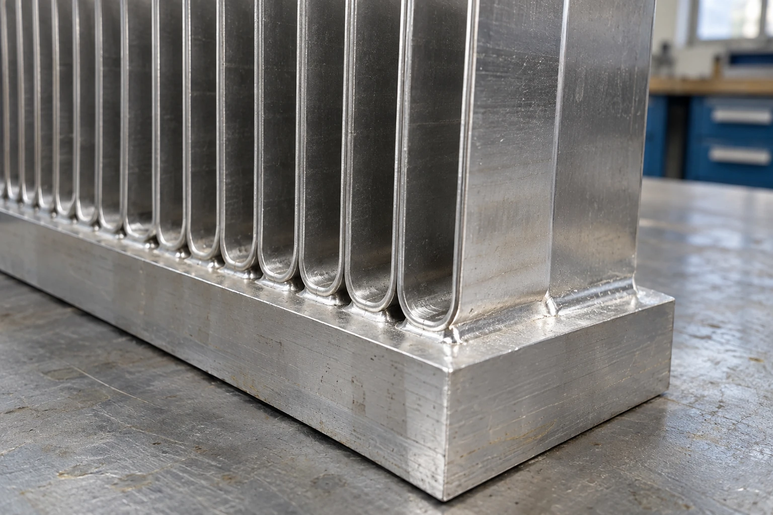
A compatible filler and thermal cycle create a metallurgical connection. Define joint clearance, fixture support, and post-process distortion checks.
Soldered assembly
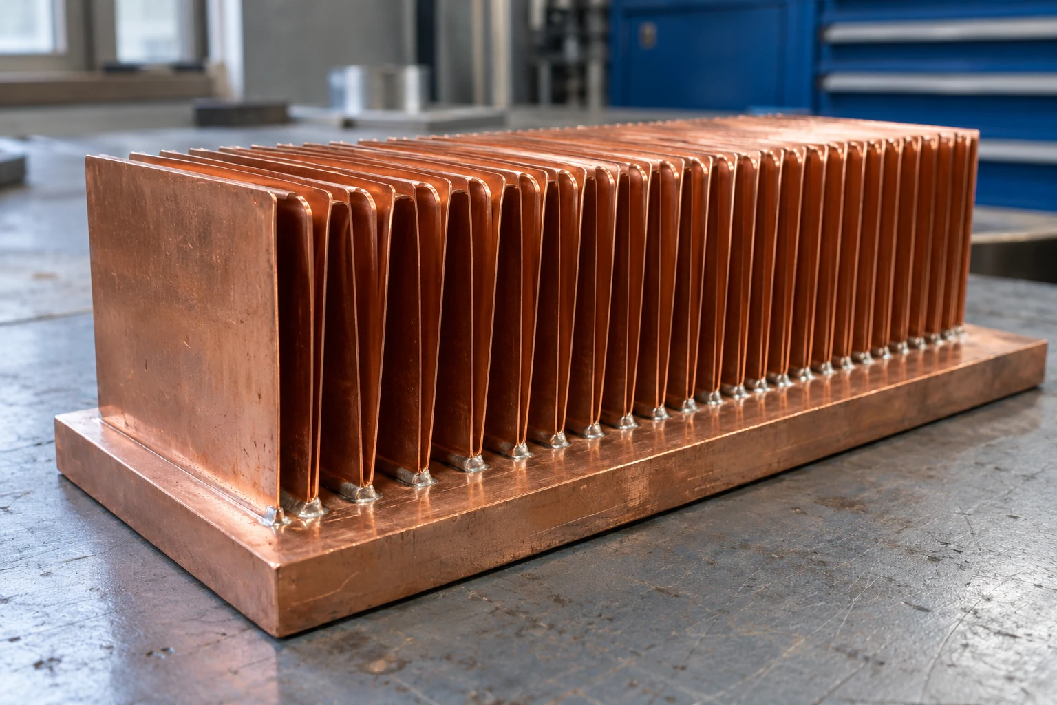
Suitable material and surface preparation support controlled wetting. Review solder coverage, voiding, and service temperature.
Thermal adhesive assembly
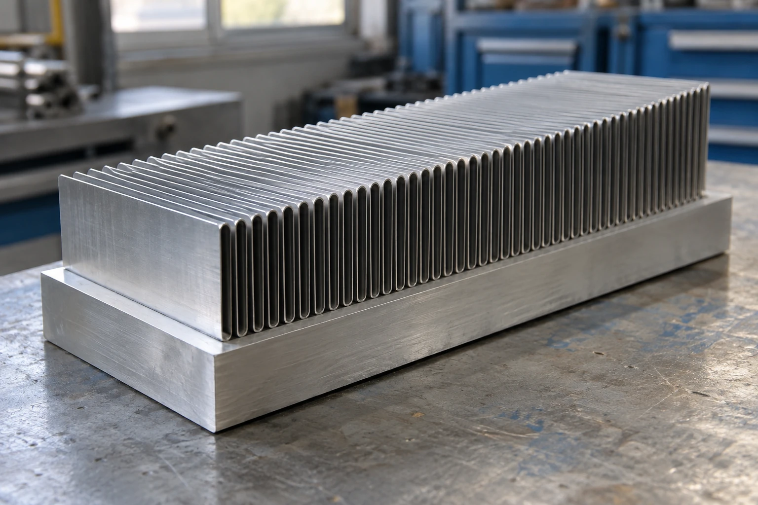
A controlled bondline offers joining flexibility. Verify cure, bond thickness, adhesion, and temperature cycling.
Choose the joining route around your material pair and operating temperature.
Review My Joining RequirementsMatch the Fin Core to the Installed Airflow
Fin density only helps when air can pass through it. We consider your fan operating point, duct geometry, and bypass paths together.
Inputs for an airflow review
- Fan curve and speed
- Duct cross-section and direction
- Inlet air temperature
- Filter and grille losses
- Noise and dust requirements
Folded Fins in Real Equipment Envelopes
Compact fin cores support equipment where controlled airflow, limited space, and repeatable assembly shape the cooling solution.
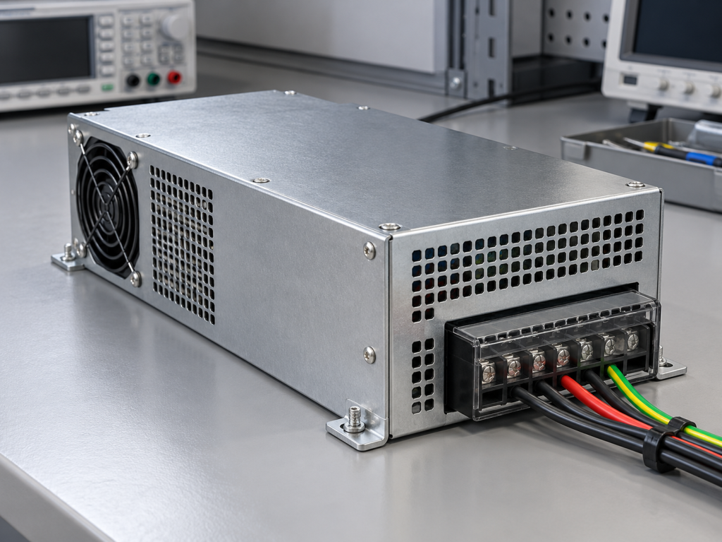
Industrial power supplies
Fit a lightweight fin core into the forced-air path while maintaining electrical clearances and service access.

Telecom and networking
Coordinate compact cooling with board layout, ducting, and continuous equipment operation.
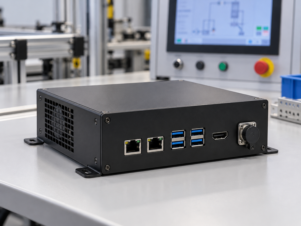
Industrial and edge computing
Work around connectors and component keep-outs while managing the actual enclosure airflow.
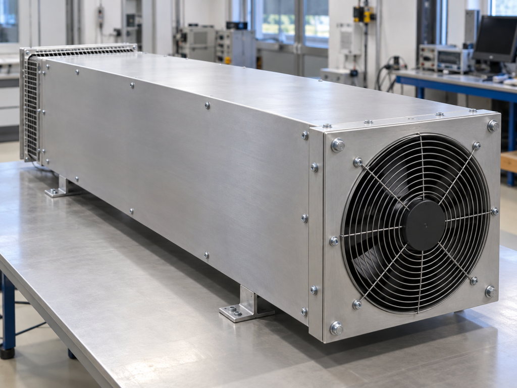
Air-cooled heat exchange assemblies
Integrate a folded core into an engineered air-side assembly with defined joining and mounting interfaces.
Custom Interfaces That Simplify Final Assembly
The fin core, base, mounting features, and thermal interface are designed as one assembly so your production team can install it consistently.
- Approved drawing revision
- Defined contact surface
- Accessible fixing points
Mounting pattern
Define hole positions, thread engagement, tooling access, and the assembly datum.
Thermal contact face
Specify local flatness, surface finish, contact area, and the selected TIM.
Keep-out zones
Preserve clearance around fasteners, connectors, insulation, and adjacent components.
Controlled clamping
Coordinate torque, load spread, and hardware to protect the device and the fin core.
A Controlled Route from Strip to Finished Assembly
Forming, joining, machining, and inspection follow the same drawing and process revision from first article to repeat orders.
Material confirmation
Verify strip and base materials, temper, thickness, and lot identification.
Fin forming
Control pitch, height, bend consistency, and passage alignment.
Core joining
Fixture the core and apply the approved brazing, soldering, or adhesive process.
Interface finishing
Machine specified faces and mounting features; protect the thin fins during handling.
Assembly verification
Inspect critical dimensions, joint condition, cleanliness, and agreed performance.
Protected delivery
Use core supports, part separation, revision labels, and batch-linked packing records.
Thermal Evidence You Can Use in Your System Review
A useful result includes the heat source, inlet temperature, installed airflow, and measurement locations—not only a wattage claim.
Thermal resistance is reported in K/W. Device junction temperature also includes the device internal and thermal interface temperature rises.
Defined heat input
Record effective heat load, heat-source size and location, interface material, and mounting load.
Measured air conditions
Measure flow through the ducted fin section and record inlet air temperature and air pressure drop.
Repeatable temperature readings
Identify the base hotspot and sensor positions after the assembly reaches steady state.
Comparable reporting
Keep orientation, fan setting, duct arrangement, and acceptance limits consistent between tests.
Define the test conditions and acceptance criteria before the sample build.
Plan a Thermal ValidationQuality Controls for Thin Fins and Reliable Joints
Control the characteristics that affect fit, heat transfer, and repeat supply, with inspection records linked to the approved drawing.
Fin geometry and condition
Check pitch, height, straightness, crushed passages, and handling damage.
Joint quality
Inspect coverage and alignment; verify joint integrity with the agreed sampling and validation plan.
Base and mounting accuracy
Inspect contact faces, holes, threads, datums, and customer-defined critical features.
Batch identity and protection
Link material, process, inspection, and packaging records to the supplied batch.
Documentation for your approval
- Material lot records Traceable
- First article inspection report FAIR
- Critical dimension results CMM
- Agreed joint and thermal checks Test Plan
- Certificate of conformity CoC
- Revision and change records ECO
Tell us which features and documents your quality team needs to release the part.
Build My Quality ChecklistFolded Fin Design Questions, Answered
Resolve the practical trade-offs before locking the fin geometry, material pair, and production route.
How are folded fins different from zipper fins?
Does a tighter fin pitch always improve cooling?
Can the folded core be joined to a custom base?
Can folded fins be used for natural convection?
Can heat pipes or a vapor chamber be integrated?
What do you need to begin a feasibility review?
Have a project-specific question about the fin core or assembly?
Ask Our Engineering TeamSend the Inputs That Make an RFQ Useful
A clear technical package lets engineering, quality, and procurement work from the same requirements.
Thermal and mechanical inputs
- 2D drawing and STEP model, or an envelope sketch
- Heat load, source footprint, and target temperature
- Inlet air conditions, fan curve, and duct layout
- Base material, mounting pattern, TIM, and surface requirements
Supply and approval inputs
- Prototype, pilot, and annual quantity estimates
- Target sample date and production schedule
- Critical dimensions, inspection, and document requirements
- Packaging, labels, destination, and revision control
Share the information you have to start a practical design and quotation review.
Start My Folded Fin RFQ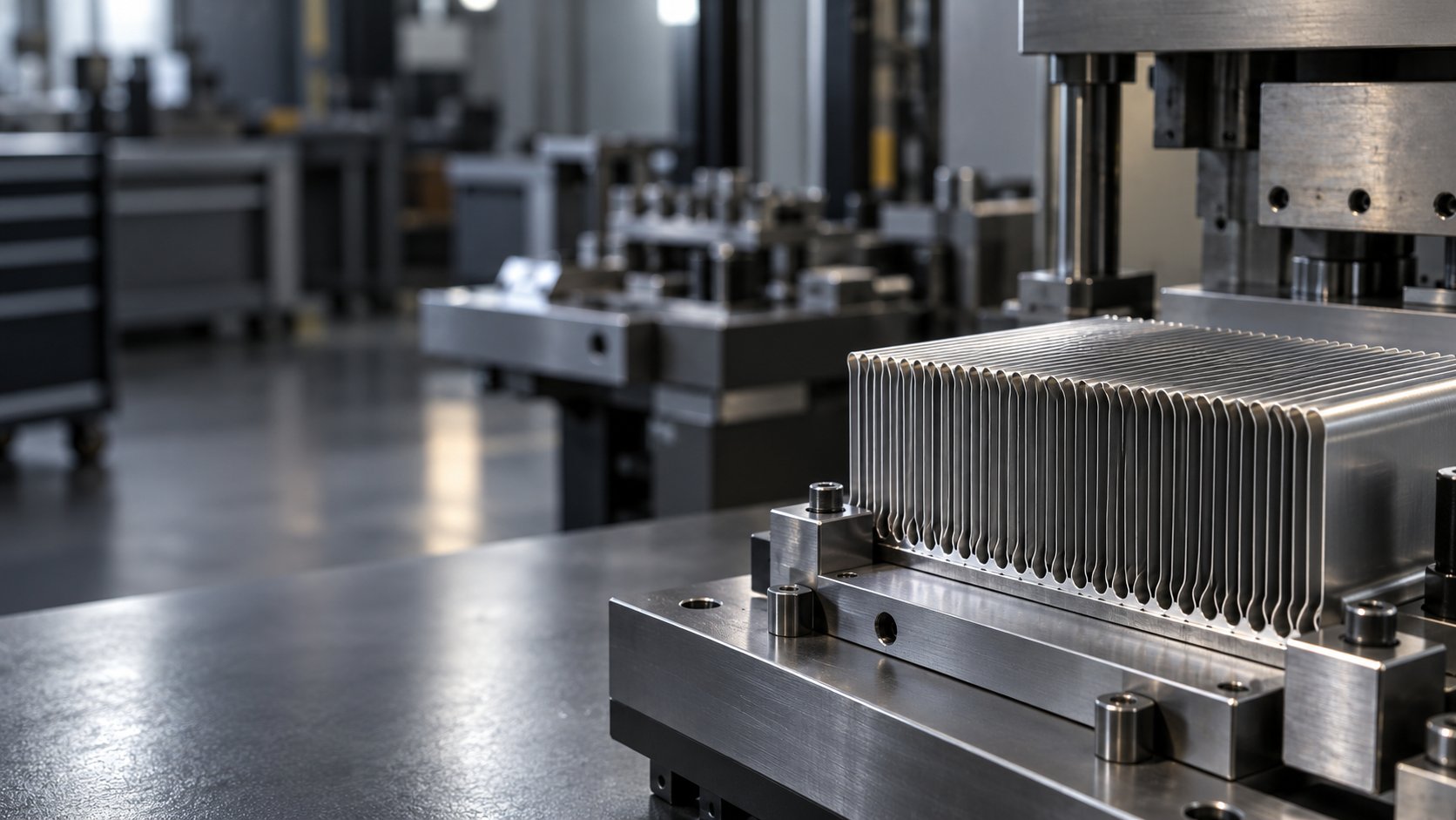
Let’s Build Your Folded Fin Cooling Solution
Share your thermal requirements and assembly constraints. Morton will help you define a practical fin core, joining route, and manufacturing plan.
Request a Folded Fin Review
Tell us what you are cooling and the space you have available.