Build Your Thermal Solution with Morton

Air & Liquid CoolingHeat sinks, heat pipe assemblies and liquid cold plates for industrial equipment.
Engineering Around Your NeedsMatch your heat load, space, mounting and operating conditions.
Traceable QualityDrawing revisions, inspection records and agreed acceptance criteria.
From Samples to SupplySupport for development samples, project orders and repeat production.
A Clear Next StepYour inquiry receives a response within one working day.

Start Your Thermal Project

Share your request below. We will respond within one working day to clarify your needs and the next step.

Optional. Choose a country, or enter a full number starting with +.

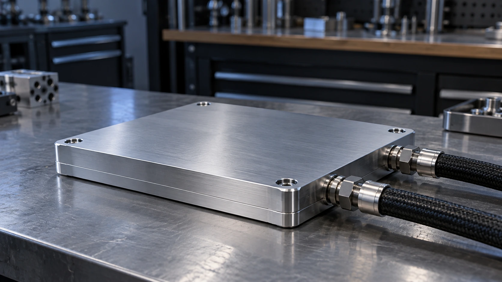
Closed aluminum microchannel cold plate with two sealed coolant hose connections on an engineering bench
CUSTOM LIQUID COOLING · MORTON

Microchannel Cold Plates for Concentrated Heat Loads

Custom copper and aluminum cold plates bring coolant close to your heat source, balancing thermal resistance, pressure drop and the space available in your equipment.

Built around your heat source

Channel layout, mounting features and ports developed for your assembly.

Validated as a component

Thermal, flow and leak requirements carried into an approved specification.

Bring your thermal target into a manufacturable design. Discuss Your Cold Plate
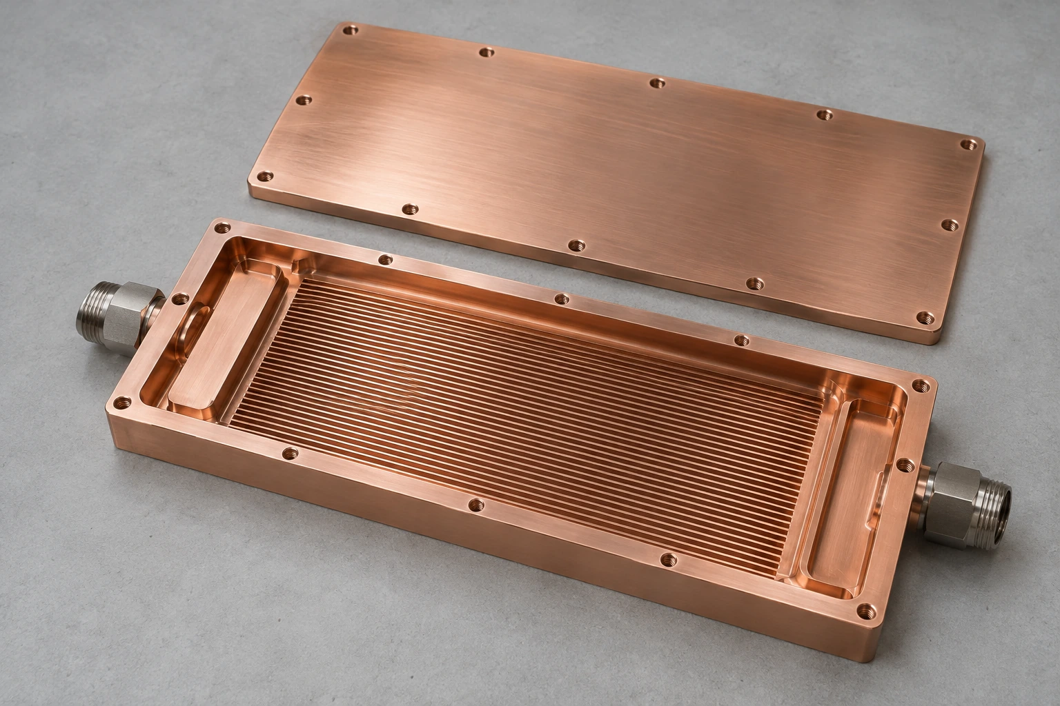
Open copper cold plate showing parallel channels and inlet and outlet header regions with the matching lid removed
Internal CNC Microchannel Passage
Pure Copper Base

What Is a Microchannel Cold Plate?

A microchannel cold plate moves liquid through closely spaced internal passages beneath a heat source. The added wetted area helps remove concentrated heat within a compact footprint.

1
Heat enters through the base
A controlled contact surface transfers heat from the device through the thermal interface.
2
Coolant reaches the channel field
Inlet distribution guides liquid across the active area instead of leaving flow to chance.
3
Heat leaves with the fluid
An external cooling loop carries the absorbed heat to a heat exchanger.
Find out whether microchannels fit your thermal and mechanical envelope. Review My Application

More Cooling Area. A Better Fit for Your Hotspot

Fine internal passages and a purpose-built base let you address local heat flux while keeping the whole cooling loop in view.

Target concentrated heat

Place the active channel area under the heat source to shorten the path from base to coolant.

Use limited space effectively

Integrate heat transfer area into a low-profile plate rather than relying on a large external fin stack.

Control flow deliberately

Size channels and manifolds together to balance distribution with available pump head.

Simplify equipment integration

Combine the thermal interface, mounting pattern and fluid connections in one controlled component.

Turn your heat map and space constraints into a practical starting point.

Share My Thermal Requirements

Flow Distribution Starts Before the First Channel

A dense channel field only works when coolant reaches the intended area. We review manifold geometry, channel resistance and air release as one flow path.

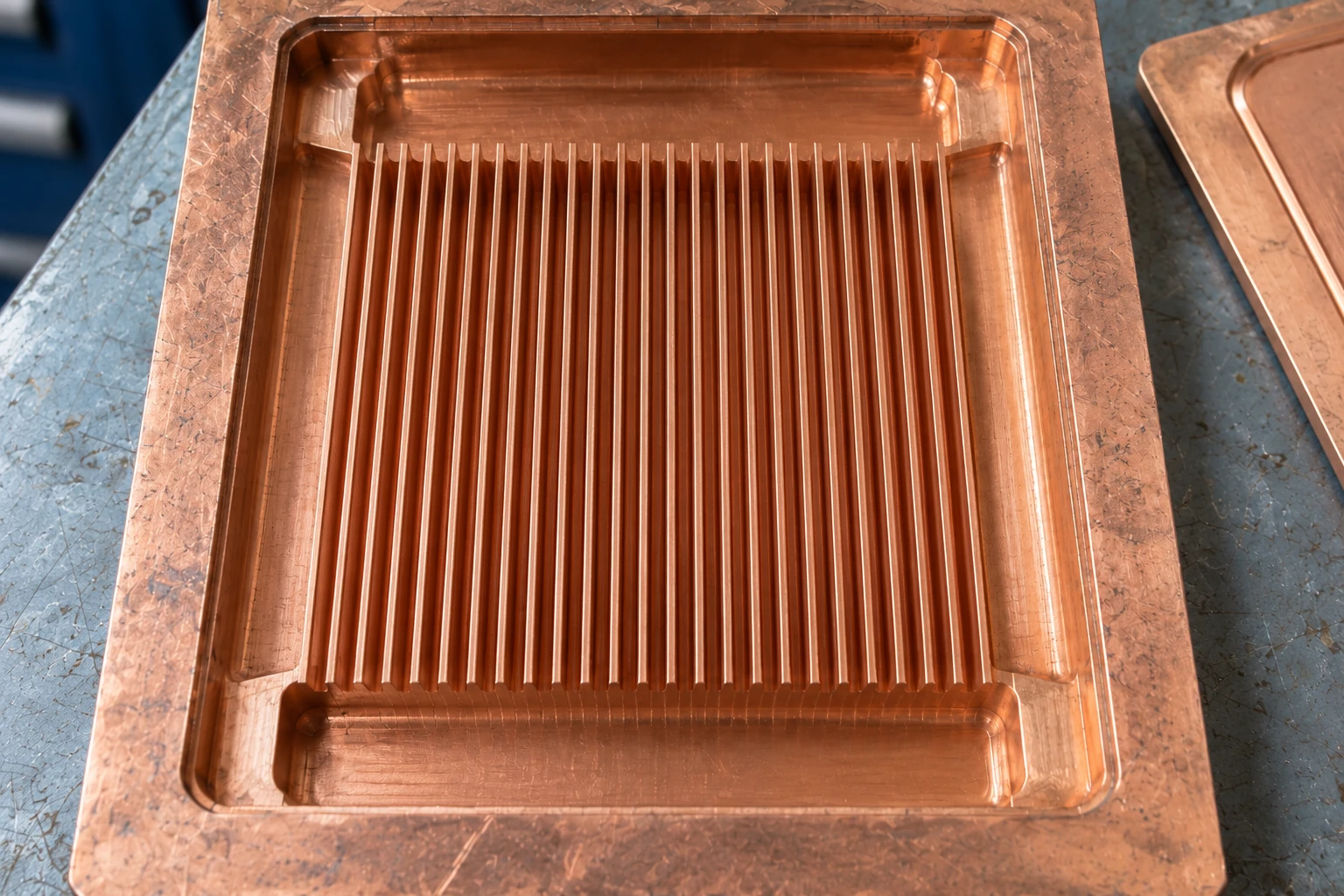
Internal Hydraulic Flow Path Channel & Header Detail
Microchannel headers photo
1

Feed the active area

Shape the inlet region around the footprint and location of the heat source.

2

Balance heat transfer and pumping

Assess channel width, depth and length against the loop flow rate and pressure budget.

3

Plan filling and cleanliness

Consider orientation, trapped air, flush access and particle control before freezing the design.

Review the flow path before committing to a finished plate.

Request a Flow-Path Review

Thermal Performance You Can Reproduce

Evaluate thermal resistance together with heat-source size, inlet temperature, coolant flow and plate-only pressure drop.

0.024 K/W
Base hotspot to inlet water
49 °C
Measured base hotspot
23 kPa
Pressure drop across the plate
1,000 W
Effective heat load
Experimental Test Ledger & Boundary Conditions
Empirical Test Bench Record
Plate and heat source
250 × 200 × 20 mm aluminum plate; 80 × 80 mm heat source.
Coolant conditions
Water at 25 °C inlet temperature and 10 L/min.
Measurement boundary
Pressure measured at the plate ports; external hoses, filters and the pump excluded.
Performance definition
Rθ = (base hotspot temperature − inlet coolant temperature) / effective heat load, after subtracting measurable fixture bypass losses.
Recorded PCS project test point. Operating media and conditions are defined separately for each design.

Get a thermal target evaluated against a defined test condition.

Define My Test Point

Choose the Metal Around the Whole Cooling Loop

Copper and aluminum offer different conductivity, mass and manufacturing options. The right choice also depends on every wetted material and the coolant chemistry.

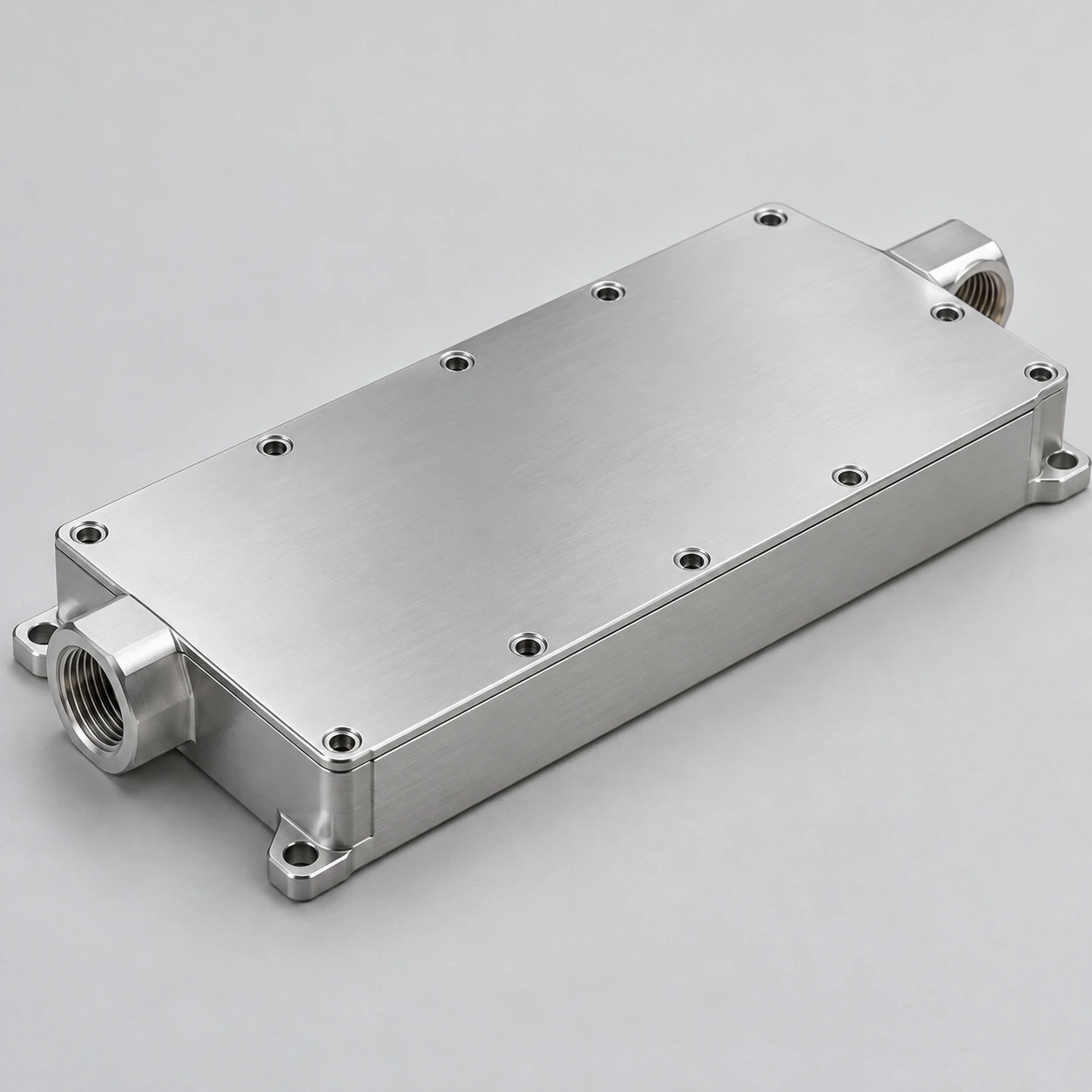
Closed machined aluminum liquid cold plate with opposite-end threaded ports 6000-Series Aluminum Alloy

Aluminum

Lightweight & Integrated

A lower-mass option for larger contact areas and integrated mounting features. Review alloy, joining route and corrosion protection with the cooling loop.

  • Optimal for multi-kW power cabinets and vibration-sensitive systems.
  • Use an inhibited water/glycol mixture validated for the complete wetted-material set.
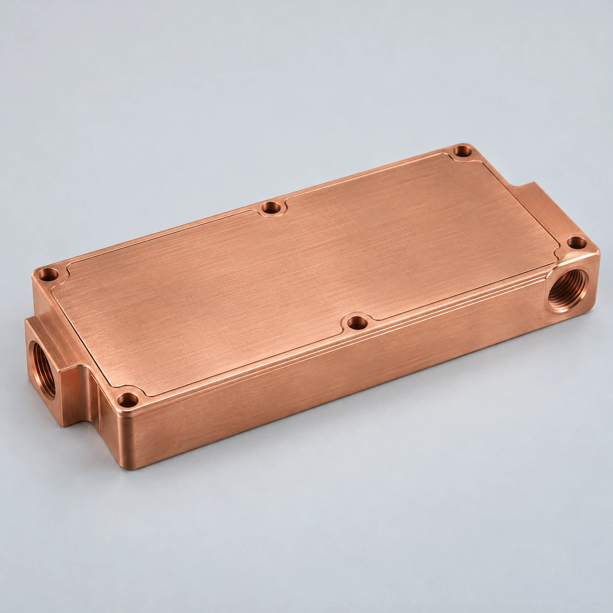
Closed copper liquid cold plate with two threaded fluid ports C1100 / T2 Copper

Copper

Maximum Heat Flux Density

Higher bulk thermal conductivity can help with compact hotspots. Review weight, surface condition and compatibility with other wetted metals.

  • About 390 W/(m·K) at room temperature; use data for the specified copper grade.
  • Ideal for dense semiconductor devices, laser diodes and RF amplifiers.

Select the base material with thermal and loop compatibility in mind.

Compare Material Options

Built Around Your Contact Surface and Connections

The contact area, mounting loads and fluid connections are reviewed together so the plate can move from your CAD assembly into production.

Match the installation

Review hole position, thread engagement, fitting clearance and service access.

Control the thermal interface

Define flatness, finish, TIM thickness and clamping load together.

Manufacturing ranges are reviewed as a combination of material, geometry and joining route.
Engineering Specification Matrix Manufacturing Boundaries
Typical outer envelope 40–250 × 40–300 × 8–30 mm
Typical channel width 0.5–1.5 mm
Typical channel depth 1–3 mm
Machined contact flatness Typically ≤0.05 mm over 100 mm
Finished thermal interface Ra 0.8–1.6 μm where specified
Ports and mounting Defined by the approved drawing

Check fit, interface quality and service access before sampling.

Send My Drawing

Protect the Channels from the First Fill

Coolant specification and particle management protect the thermal performance you designed into the plate.

01

Control particles

A 50 μm absolute filter is a common starting point; final filtration follows the minimum passage and cleanliness specification.

02

Confirm coolant chemistry

Use a corrosion-inhibited fluid qualified for the complete wetted material set.

03

Account for glycol

Verify thermal resistance, pressure drop and the pump operating point with the selected glycol concentration.

04

Manage filling and temperature

Plan flushing, air removal and draining, and keep inlet temperature above the local dew point where condensation is a concern.

Make coolant and cleanliness part of the design input.

Review My Cooling Loop

For Equipment Where Heat Is Concentrated

Microchannel cooling fits equipment that needs a controlled liquid path close to a compact, high-load heat source.

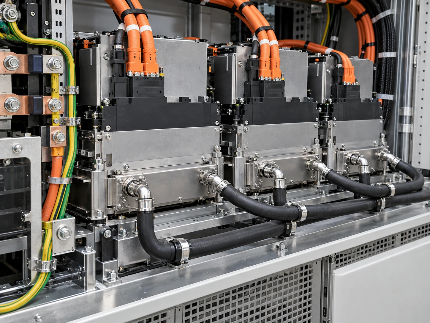
Liquid-cooled power conversion modules with insulated power wiring and paired coolant hoses Power Systems

Energy Storage PCS

Cool compact power modules with flow and pressure targets linked to the system loop.

Closed liquid cold plate mounted over the processor in an industrial computing tray Dense Compute

Industrial Computing

Bring liquid close to dense processor loads while reviewing board clearance and connection access.
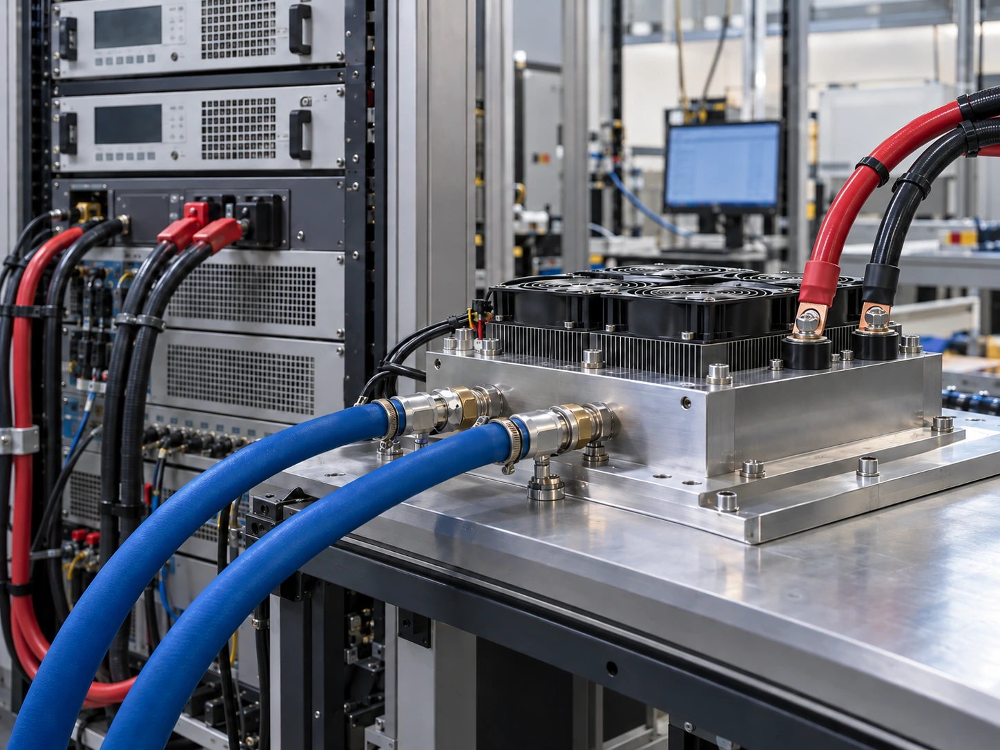
Electronic power-load module with separate blue coolant hoses and insulated electrical ring-lug terminals Test & Lab

Power Test Equipment

Support concentrated electronic loads with defined coolant conditions and repeatable measurement.
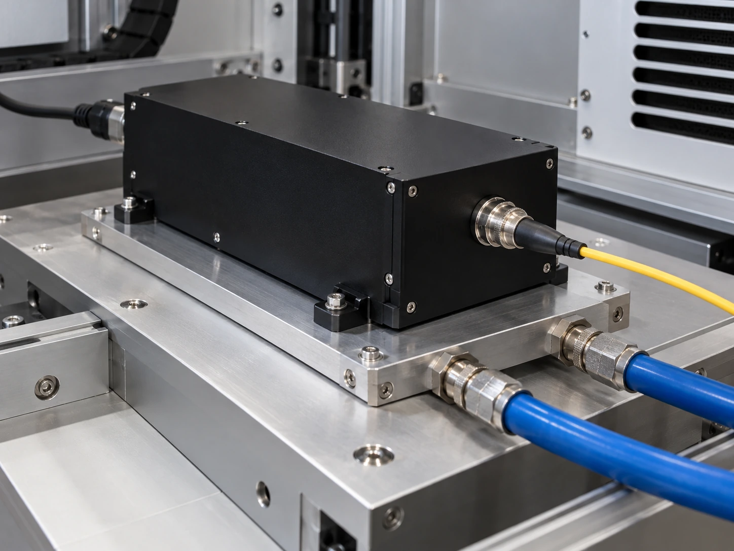
Sealed laser source mounted on a closed liquid cold plate with separate optical fiber and coolant connections Photonics

Laser & Precision Equipment

Review localized heat input, stable coolant delivery and the mechanical interface together.

Start with the heat source and operating conditions in your equipment.

Discuss My Equipment

From Thermal Brief to an Approved Cold Plate

One project team connects requirements, design, samples and controlled production documents.

01 Phase 1

Define the operating window

Collect heat load, source footprint, temperature limits, flow, pressure budget, coolant and annual demand.

Output Deliverable
Agreed input brief
02 Phase 2

Review the design

Develop the channel field, manifolds, base, ports and mounting details with DFM and thermal-fluid review.

Output Deliverable
Drawing and review actions
03 Phase 3

Build and validate

Make development samples and check fit, thermal response, pressure drop and sealing against the test plan.

Output Deliverable
Sample and validation records
04 Phase 4

Freeze and release

Approve the drawing, acceptance criteria, inspection plan and packaging before repeat supply.

Output Deliverable
Controlled production package

Give engineering and purchasing the same starting point.

Start a Design Review
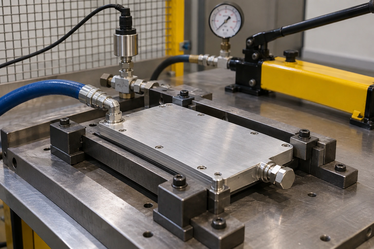
Closed liquid cold plate restrained in a hydrostatic pressure-test fixture with a capped outlet and pressure instrumentation
HYDROSTATIC PROOF & LEAK CHECK FIXTURE 0.6 MPa Proof

Pressure Tested. Cleaned. Dried. Traceable

All rated and test pressures on this page are gauge pressures. For the 0.3 MPa rated design, proof pressure, final leak testing and identification follow the approved control plan.

Hydrostatic proof test

0.6 MPa for 10 minutes on the defined 0.3 MPa rated design, with no leakage or permanent deformation.

Final gas leak check

After draining, cleaning and drying, test using dry air or nitrogen under the approved method; typical acceptance is ≤0.05 sccm equivalent air.

Release with records

Link material lot, drawing revision, inspection results and leak records to the delivered batch.

Traceable Quality Records Package
FAI report Dimensional inspection Leak-test records Material traceability

Bring your critical acceptance criteria into the control plan.

Discuss Quality Requirements
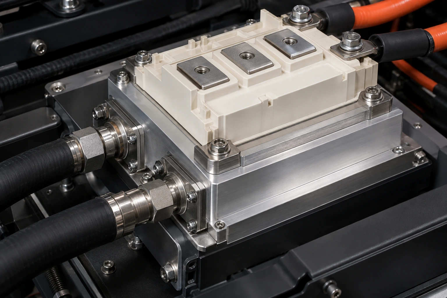
Insulated power module mounted on a closed aluminum cold plate with two coolant connections
PCS CABINET INTEGRATION & QUICK-CONNECT HARNESS 1 kW Tested

A Compact PCS Module, Validated at 1 kW

For a UAE energy-storage PCS project, an aluminum microchannel plate combined a defined flow path with clean, traceable liquid-cooling assembly.

The requirement

Remove 1,000 W from an 80 × 80 mm module within a 250 × 200 × 20 mm plate, with plate-only pressure drop below 30 kPa.

The design response

Use an inlet distribution region, controlled channel cleanliness, specified coolant compatibility and a finished contact surface.

The verified result

At 25 °C inlet water and 10 L/min, the base hotspot reached 49 °C with 23 kPa pressure drop. The first delivery included 240 plates.

1.4 K
Approximate water temperature rise
0.3 MPa
Rated working pressure
240
Plates in the first delivery
The 40 °C inlet condition with inhibited water/glycol was tested separately before the operating specification was frozen.

Use a comparable test boundary to assess your next PCS design.

Review My PCS Project

A Clear Route from Samples to Repeat Supply

Plan engineering validation and purchasing milestones with defined quantities, drawings and release conditions.

Phase 1

Start with engineering samples

Paid development samples can start from one piece. Joint liquid-cooling development typically takes 4–8 weeks for first samples and testing.

Phase 2

Plan the production release

Liquid cold plate production MOQ is typically 20–50 pieces. Routine liquid-cooling orders commonly take 30–45 days after the agreed release conditions are met.

Phase 3

Keep every revision aligned

Receive drawing and inspection documents, agreed packing identification and engineering change control for repeat orders.

Release Package Deliverables
PDF / DWG drawings STEP models FAI & inspection plan Batch identification

Share your target quantity and timing for a practical supply plan.

Plan My Sample Order

Microchannel Cold Plate Questions, Answered

Resolve the design and procurement details that matter before you request a sample.

What information do you need to review a design?
Send the heat load, heat-source footprint and location, target base temperature, inlet coolant temperature, available flow, pressure budget, coolant type, mounting space and expected quantity. A drawing or STEP model helps define the interface.
Is microchannel cooling always the best choice?
It suits concentrated heat loads and compact envelopes. The final choice depends on the pump, fluid quality, thermal target and maintenance conditions; we review those boundaries before fixing the flow geometry.
Can I use water or a water/glycol mixture?
Short bench tests may use filtered water. Long-term operation uses a corrosion-inhibited coolant validated for the wetted materials. Glycol concentration changes viscosity, pressure drop and heat transfer, so the final mixture is tested.
How do you manage blockage and trapped air?
We define channel cleanliness, flushing and filling requirements together. Filtration is selected against the minimum passage, and orientation and manifold design are reviewed for air release.
Do you test every plate for leakage?
Industrial liquid cold plates receive individual pressure and gas leak checks under the approved control plan. The test pressure, stabilization period and acceptance limit follow the rated design and customer requirements.
Can you support a small initial order?
Yes. Paid engineering samples can start from one piece, with first-round quantity and test scope agreed for the project. Typical liquid cold plate production MOQ is 20–50 pieces, depending on complexity and tooling.

Get an answer tied to your drawing and operating window.

Ask an Engineer
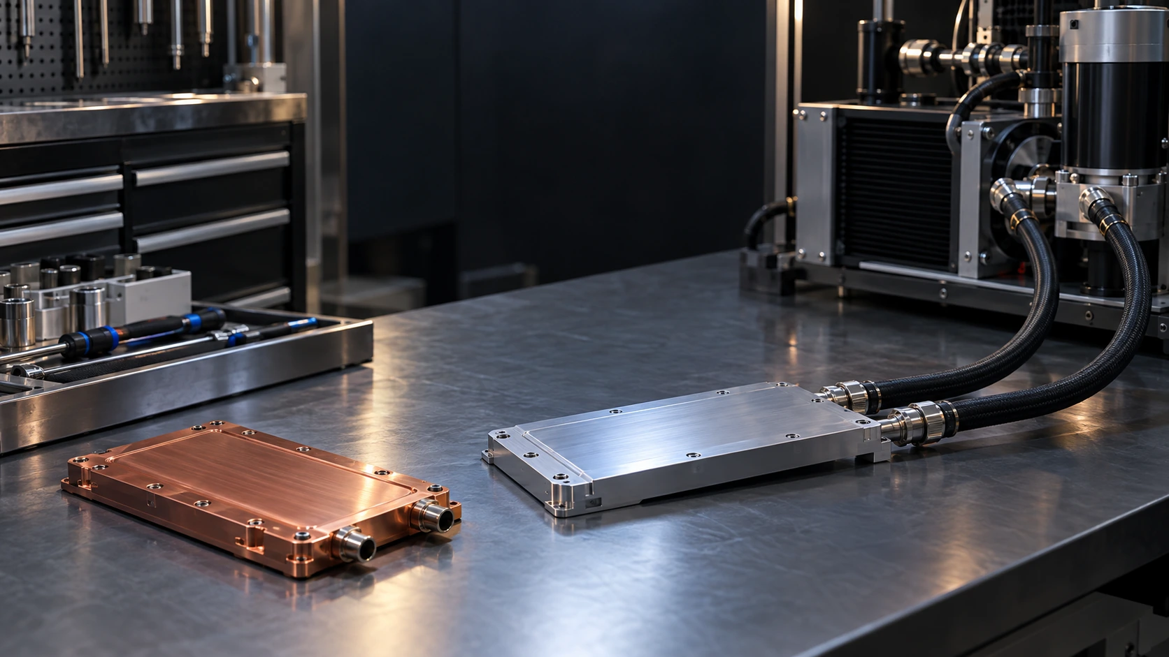
Closed aluminum and copper cold plates on an organized liquid-cooling engineering bench

Let’s Define Your Next Cold Plate

Share your heat source, cooling conditions and installation limits. Our team will help define a manufacturable microchannel design and a clear validation path.

Application-led design
Thermal and mechanical inputs reviewed together.
Defined test conditions
Thermal resistance and pressure drop evaluated as a pair.
Controlled quality
Drawing, material and leak-test records linked to delivery.
From sample to supply
Development quantities and repeat orders planned together.

Engineering Inquiry

Complete the fields below to start your thermal-fluid and DFM review.

Your information stays confidential. Initial response within one working day.