
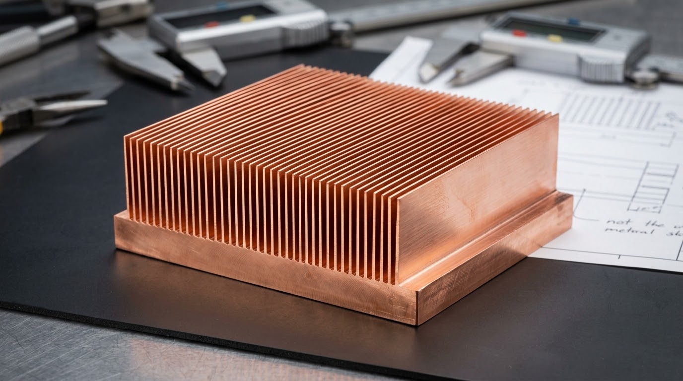
Skived Fin Heat Sinks for Compact Power Electronics
Bring more cooling surface into limited space with integral copper or aluminum fins, engineered around your heat load, airflow and mounting envelope.
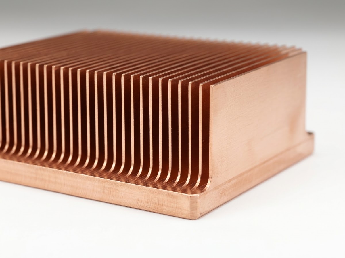
One Piece. A Direct Path from Base to Fin
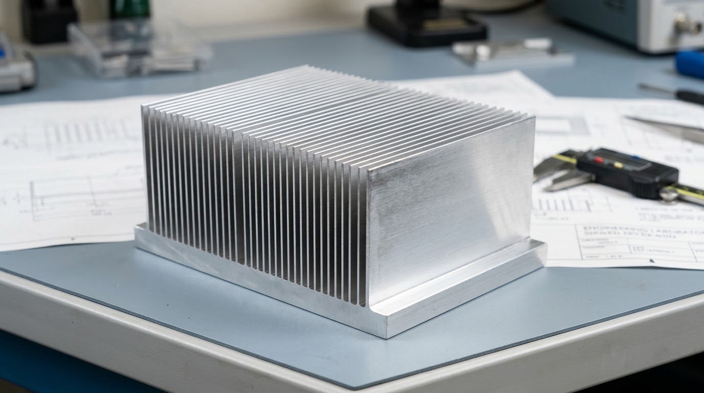
Skiving cuts and raises thin fins from the parent metal, keeping every fin connected to the base without an added fin-to-base bonding layer.
More Cooling Surface, with the Details Under Control
Get the benefit of dense fins while keeping airflow, assembly and manufacturing consistency part of the same design decision.
A continuous thermal path
Eliminate the separate fin-to-base joint. Keep heat moving through a single metal structure.
Surface area in tight spaces
Fit thin plate fins into compact equipment. Match density to the pressure available from the installed fan.
A defined mechanical interface
Machine mounting holes, cutouts and contact faces around the approved assembly. Reduce fit issues during integration.
Repeatable production geometry
Control fin thickness, clear gap and straightness against the drawing. Carry the approved geometry into every production batch.
Turn the thermal goal into a manufacturable fin structure.
Request a Geometry ReviewCopper or Aluminum? Choose for the Whole Assembly
The right material balances heat spreading, weight, finishing and cost, rather than conductivity alone.
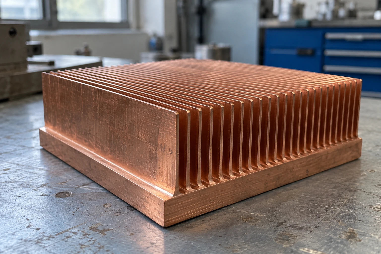 Integral Copper Fin Profile
Copper · C1100 / T2
Prioritize heat spreading around concentrated heat sources. A useful route for compact power assemblies where mass is acceptable.
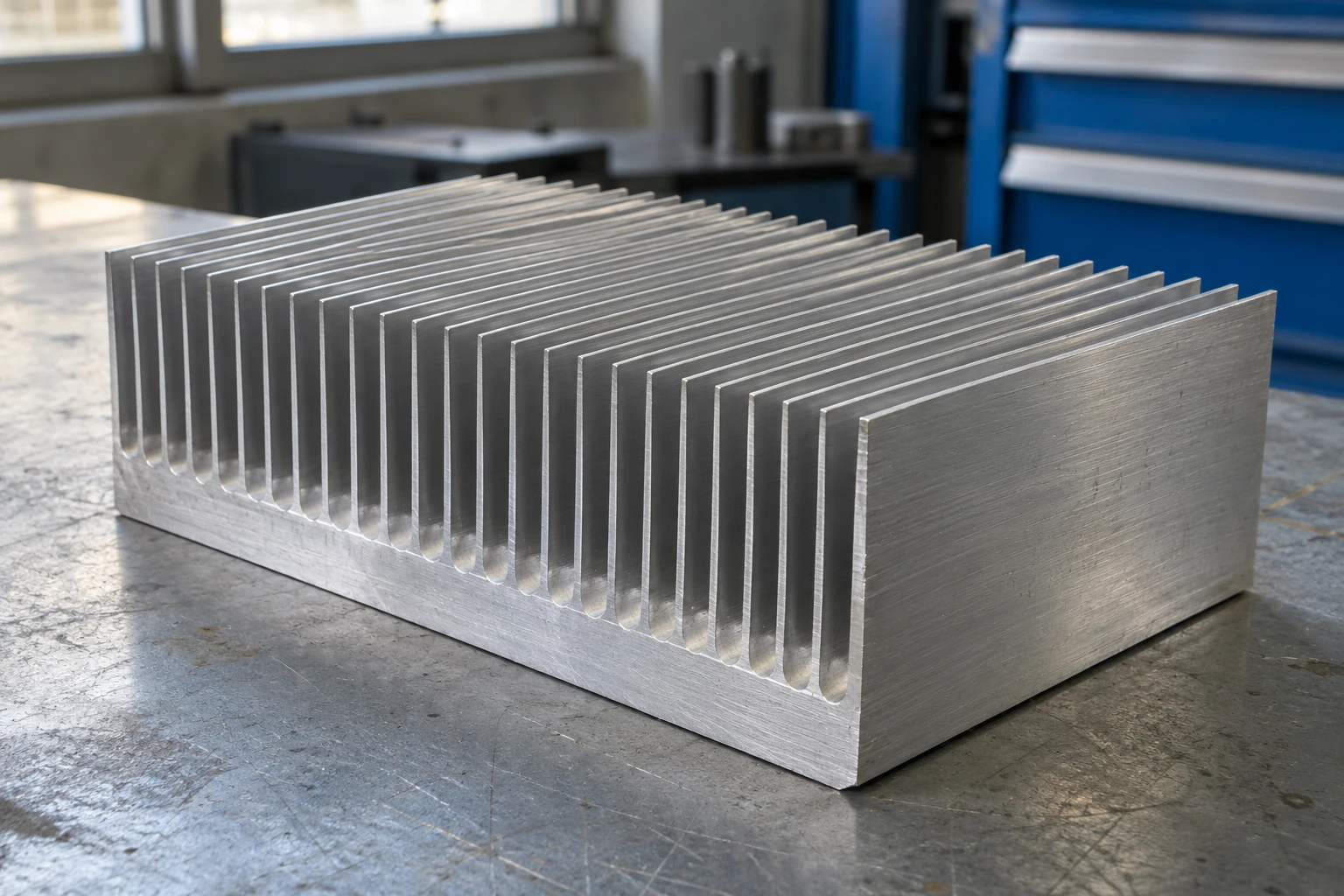 Integral Aluminum Fin Profile
Aluminum · 6063 / 1060
Prioritize a lighter assembly and practical surface treatment options. Balance fin geometry and airflow against the required temperature limit.
Share the constraints that matter most to your assembly.
Compare Material OptionsDefine the Fin Geometry Before You Freeze the Design
Use these normal manufacturing ranges to start the discussion, then review the complete combination against strength, airflow and assembly requirements.
| Materials | 6063 / 1060 aluminum; C1100 / T2 copper |
| Typical overall envelope | 30–250 × 30–350 × 10–100 mm |
| Fin thickness | 0.3–0.8 mm |
| Clear fin gap | 0.8–2.5 mm |
| Contact face and mounting features | CNC finished to the approved drawing |
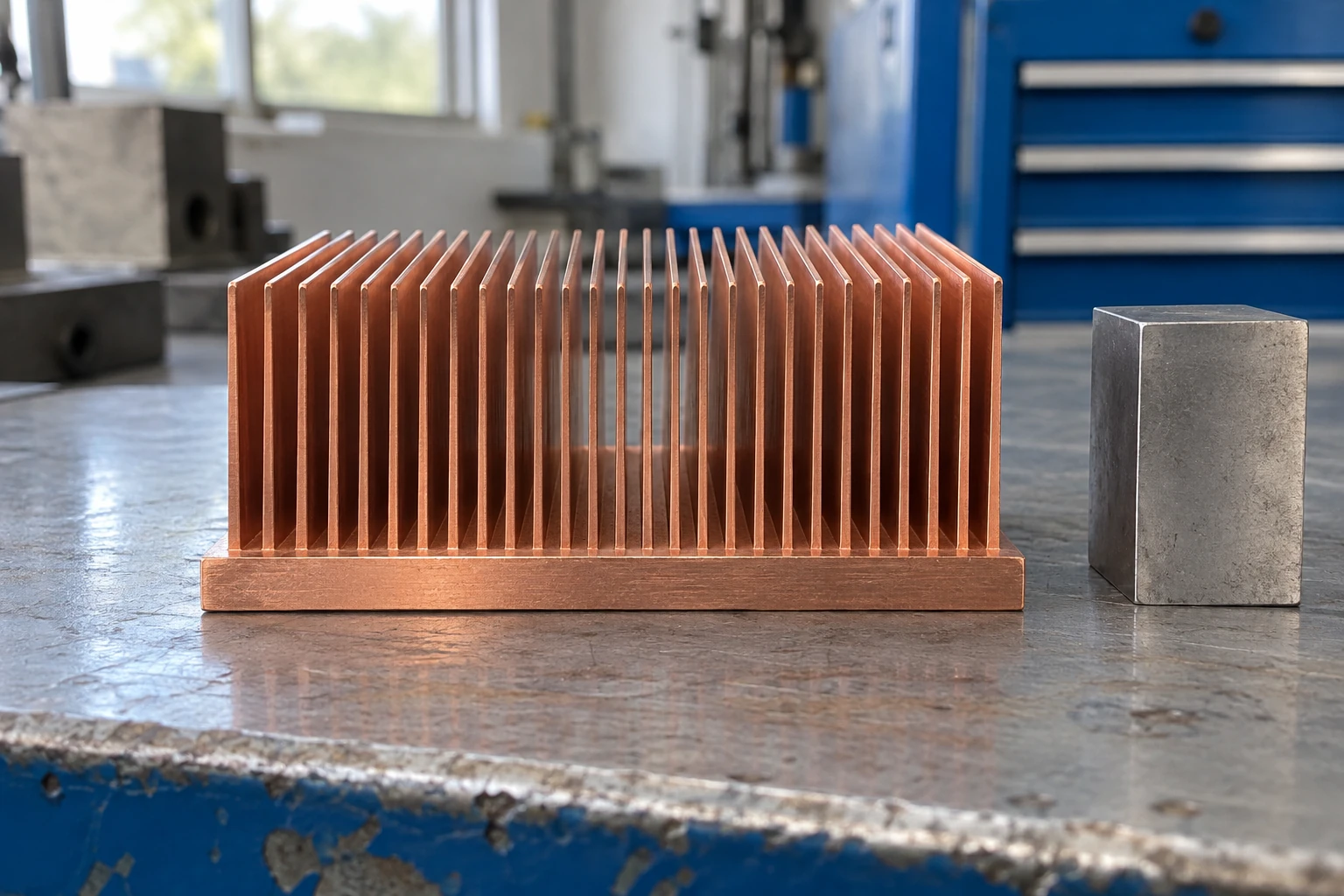
Send your envelope and contact footprint for a practical geometry check.
Check My DimensionsDense Fins Need the Right Airflow Path
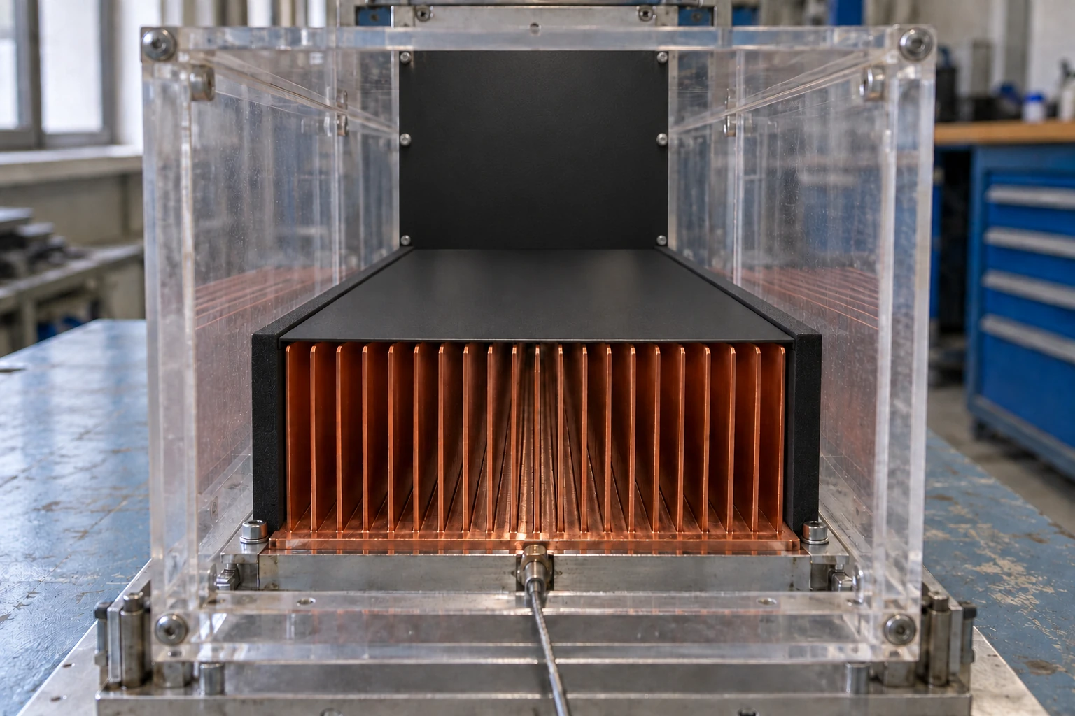
More fins help only when air reaches the channels. We evaluate the heat sink together with the fan, duct and pressure losses in the installed system.
Measure through-flow
Use the airflow that actually passes through the fin channels, with the duct and enclosure in place.
Check the working point
Match heat sink pressure loss with the fan curve and the losses elsewhere in the system.
Control bypass and blockage
Review inlet clearance, sealing, dust exposure and the exit path to make the available airflow useful.
Bring the fan curve and duct layout into the thermal review.
Review My Airflow PathMake the Contact Interface Work as Hard as the Fins
A good fin structure still depends on a flat contact face, the right interface material and a controlled mounting load.
Specify the functional area, flatness and roughness from the device and TIM requirements. Keep finishing requirements tied to the final treated part.
Choose thickness and compression from the real gap and permitted device load. A thicker pad is not automatically a better thermal interface.
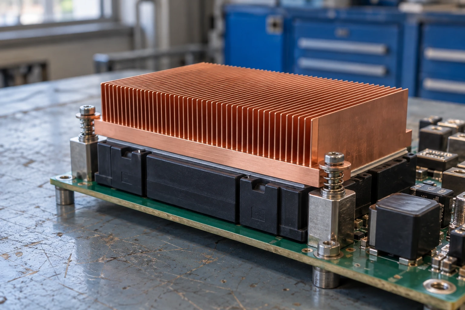
Review hole positions, spring hardware, torque and board clearance together. Maintain contact without overstressing the assembly.
Built Around Compact, High-Density Equipment
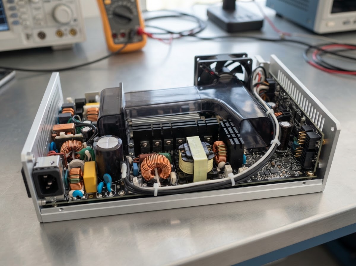
Skived fins are a practical option where concentrated heat and limited space meet a defined forced-air cooling path.
Server power supplies
Manage concentrated switching losses inside compact, ducted power stages.
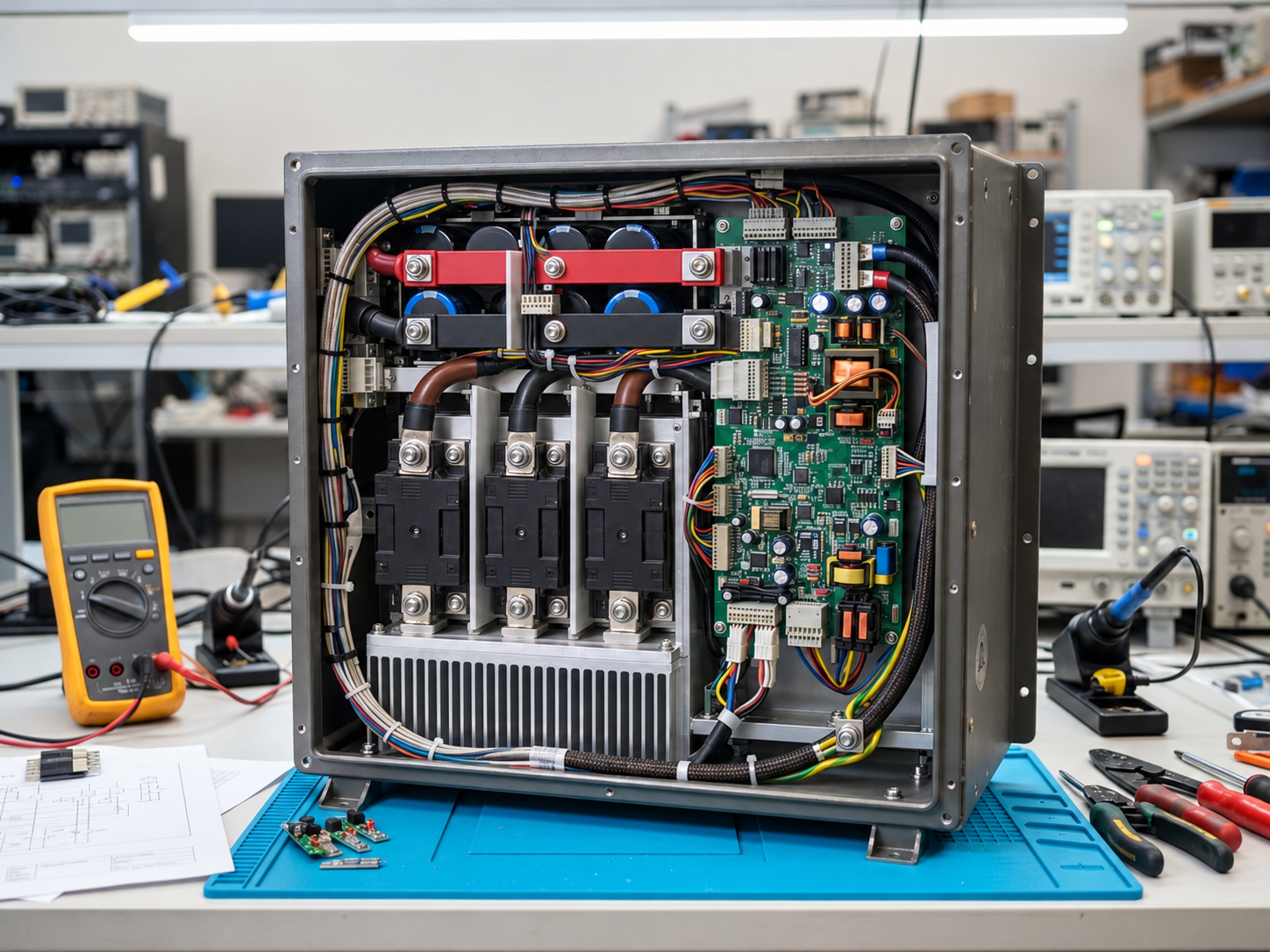
Power conversion modules
Balance heat spreading and fin pressure drop around densely packed power devices.
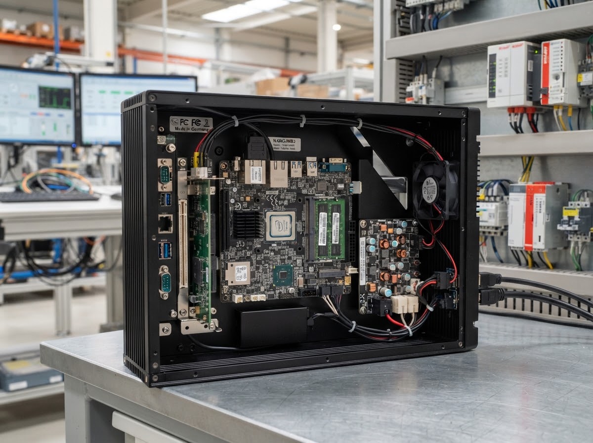
Industrial computing
Fit cooling into constrained chassis where airflow direction and mounting height are already defined.

Telecom power equipment
Match compact rectifier and DC/DC assemblies to the actual inlet conditions and service environment.
250 W in a 100 × 100 × 35 mm Envelope
A copper skived fin design helped a German server power supply OEM lower the base hot-spot temperature under the same installed test conditions.
Heat load 250 W; heat source 30 × 30 mm; inlet air 25 °C; measured through-fin airflow 60 m³/h under a duct.
C1100 copper; 0.5 mm fins; 1.2 mm clear gap; controlled 0.2 mm interface material; spring screws and inlet-flow optimization.
About 12.5 K lower base temperature; first delivery of 1,200 pieces; repeat orders of 500–1,000 pieces per month.
Define a comparable test around your own heat source and airflow.
Discuss My Thermal TargetFrom Parent Metal to a Controlled Finished Part
Keep material, skiving, machining and finishing tied to the same drawing revision so the delivered part matches the approved sample.
Confirm alloy, parent-stock dimensions and material batch identity.
Control skiving thickness, clear gap and straightness as the fins are raised from the base.
Finish contact faces, mounting holes and required cutouts from defined datums.
Protect the specified surfaces and mask thermal or grounding interfaces where required.
Check the drawing requirements, cleanliness, identification and protective packing.
Build the manufacturing route around your approved geometry.
Request a DFM Review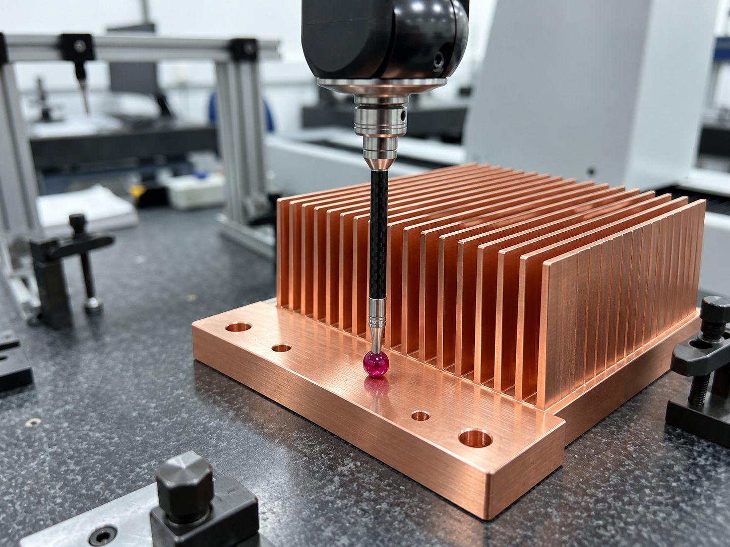
Quality Checks That Follow the Thermal Design
Control the features that affect contact, airflow and assembly, with records linked to the part revision and production batch.
Material and traceability
Link incoming material identity, work orders and inspection records to the delivered batch.
Critical dimensions
Check fin spacing, straightness, hole positions and the contact face against the control plan.
Thermal verification
Record heat-source size, power, inlet temperature, actual airflow, air pressure drop and sensor locations.
Release documentation
Provide the agreed FAI, dimensional report, material documentation and certificate of conformity.
Set the acceptance criteria before the first sample is made.
Define My Inspection PlanMake Your Drawing Ready for a Useful Engineering Review
A few clear inputs let us assess the skived fin structure, mounting interface and production route without repeated clarification.
Thermal brief
Continuous and peak losses; heat-source size and layout; inlet temperature; target base or device temperature.
Mechanical envelope
STEP or 2D drawing; height limit; mounting pattern; contact areas; clearance and mass requirements.
Airflow conditions
Installed airflow or fan curve; duct layout; pressure allowance; dust and service conditions.
Supply requirements
Sample quantity; annual demand; preferred material and finish; inspection and documentation needs.
Have a drawing or an early thermal brief? Start there.
Share My Project BriefA Clear Route from Samples to Repeat Supply
Move from engineering approval to scheduled production with a defined drawing, acceptance plan and delivery agreement.
Engineering samples
Paid samples can start from one piece. Typical made-to-drawing samples take 10–20 working days after drawing freeze.
Production approval
Confirm the approved sample, critical dimensions, finish and documents. Typical skived fin production MOQ is 50–100 pieces, depending on the design.
Repeat deliveries
Agree the forecast, batch size and order conditions. Carry the approved revision into scheduled releases and controlled engineering changes.
Questions Engineers Ask Before Choosing Skived Fins
Resolve the material, airflow and production questions that shape a practical skived fin heat sink specification.
Are skived fins always better than extruded fins?
Can you manufacture both copper and aluminum designs?
What airflow information do you need?
Can dense skived fins be used with natural convection?
Can you add mounting holes, cutouts and a finished contact face?
What should I send to request a quotation?
Let’s Engineer Your Skived Fin Heat Sink
Share your thermal target and mechanical constraints. We will review the right starting point for material, fin geometry and validation.