
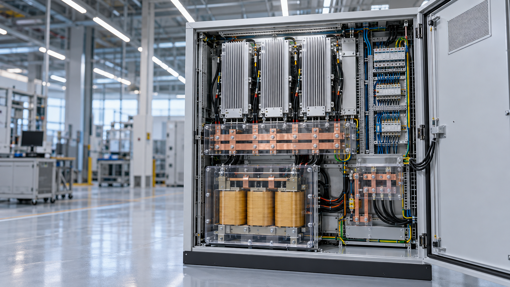
Thermal Management for Industrial Power Supplies
Custom heat sinks and liquid cold plates that turn power losses into a controlled thermal path—from your first prototype to repeatable production.
Bring your power, space and operating conditions into one cooling brief.
Discuss Your Cooling ProjectWhen Heat Becomes a Limit on Power
A power supply can meet its electrical targets and still lose its thermal margin once it is installed in the cabinet.
Hot cabinet air
A higher inlet temperature leaves less headroom for semiconductor losses.
Concentrated losses
MOSFETs, rectifiers and magnetics place heat in different areas of a compact assembly.
Restricted airflow
Filters, guards and dense fins move the fan away from its free-air rating.
Assembly variation
Surface flatness, TIM thickness and clamping force change the thermal interface.
Identify the constraint before adding more metal or a larger fan.
Review Your Thermal ConstraintsMatch the Cooling Path to Your Power Supply
Start with the installation environment, heat-source layout and service conditions—not an isolated wattage rating.
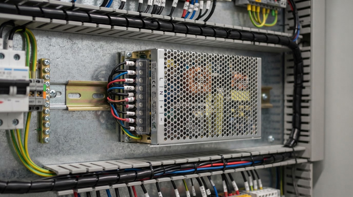
Enclosed AC/DC supplies
Limited cabinet space and warm inlet air make fin orientation and enclosure coupling critical.
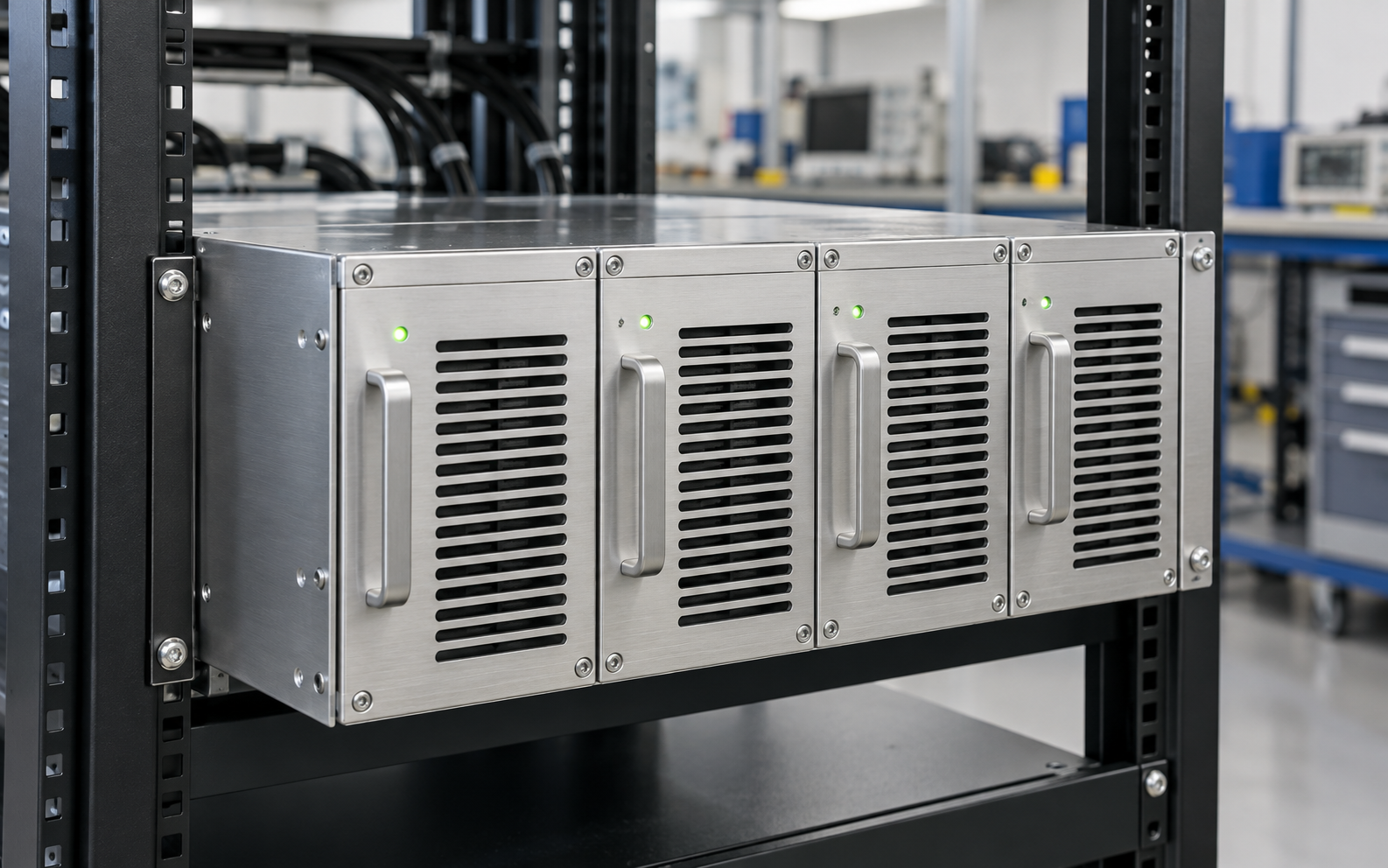
Rack-mounted rectifiers
High component density requires a clear forced-air path and efficient spreading from small hot spots.
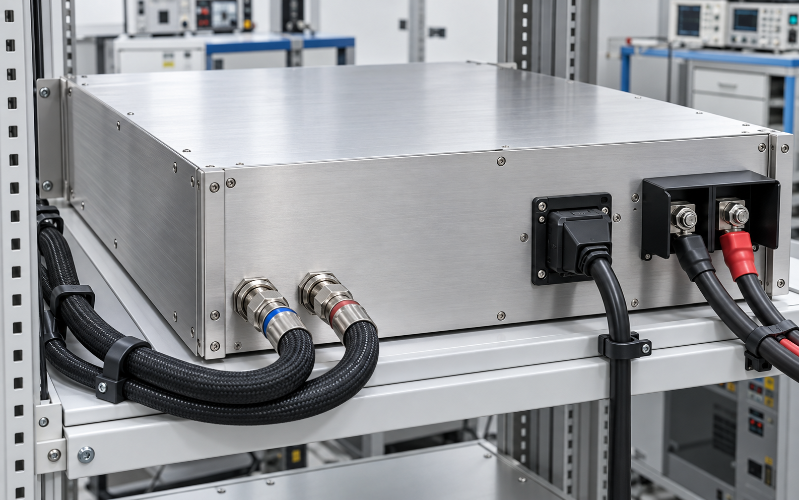
High-power programmable supplies
Continuous conversion losses can exceed the practical air-side budget in a compact chassis.
A Cooling Route for Every Thermal Constraint
Compare manufacturing routes against the same heat load, installation space and operating conditions.
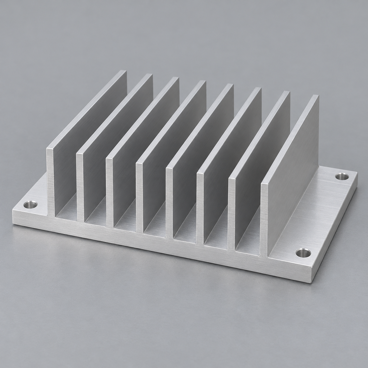
Extruded & Board-Level Heat Sinks
6063 aluminum profiles, machined interfaces and mounting features support practical cost control.
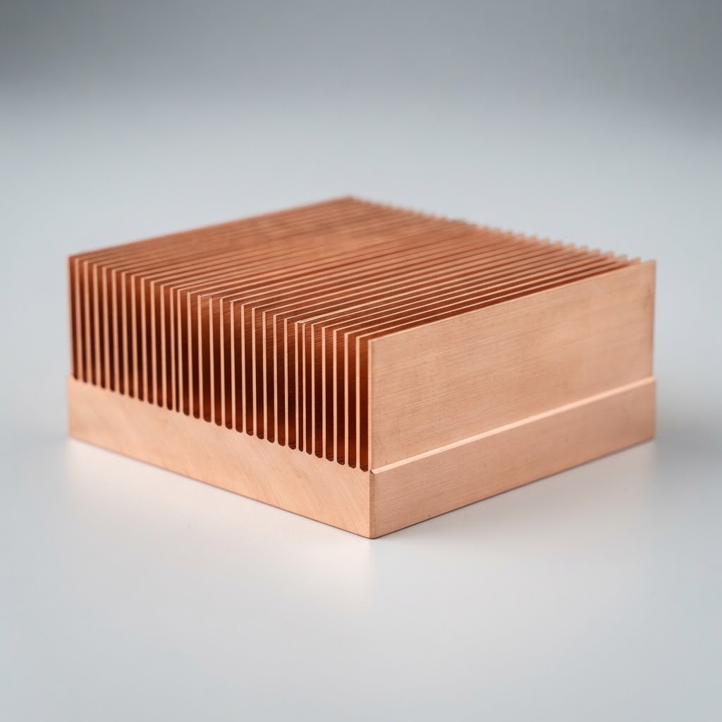
Skived Fin Heat Sinks
Integral copper or aluminum fins reduce an additional fin-to-base joint; spacing is matched to available fan pressure.
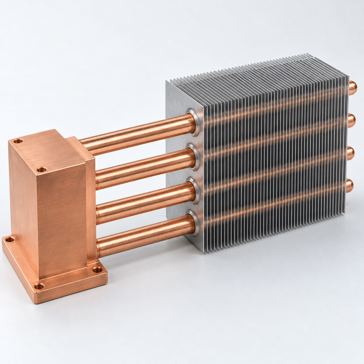
Heat Pipe & Vapor Chamber Assemblies
Move heat toward the usable fin area while validating orientation, contact load and component clearance.
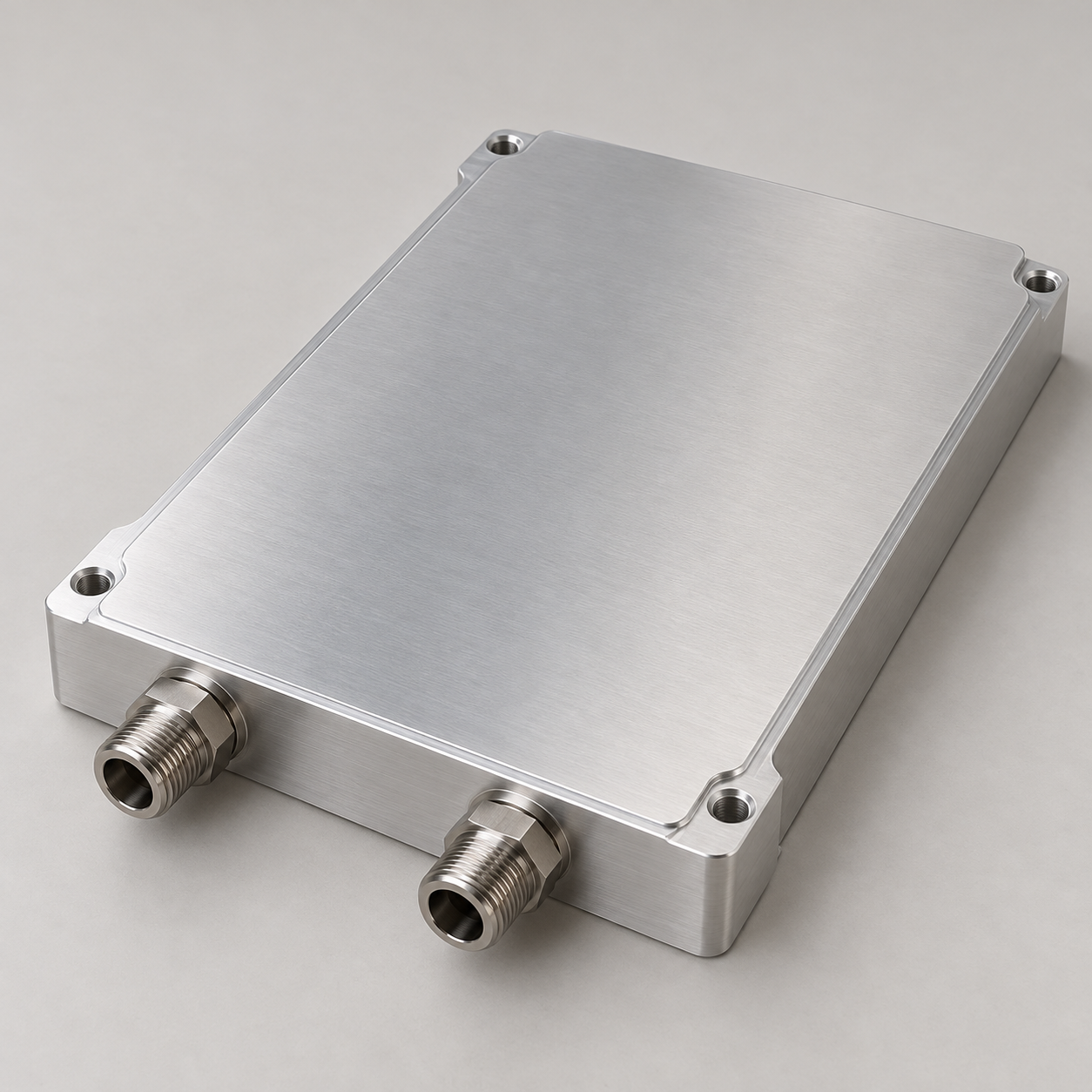
Liquid Cold Plates
Tube-in-plate, microchannel, vacuum-brazed and friction-stir-welded routes are selected around the flow circuit and mounting plane.
Design Around the Installed Operating Point
Define the loss budget and the available temperature rise, then size the thermal path against the conditions inside your equipment.
Share output power, efficiency across the load range, and the location and footprint of each heat source.
Set the allowable base temperature, worst-case inlet temperature, installed airflow or coolant flow, and the available pressure budget.
Confirm contact flatness, TIM thickness, electrical isolation, fixing force and access for assembly.
A practical thermal budget
This steady-state example assumes all 105.3 W enters one heat sink. Allocate losses to the actual cooling paths, validate installed airflow, and check junction and interface temperature rises separately.
Liquid Cooling Without Interface Surprises
A cold plate has to fit the complete circuit: the heat source, coolant, pump, connections and the way it is assembled.
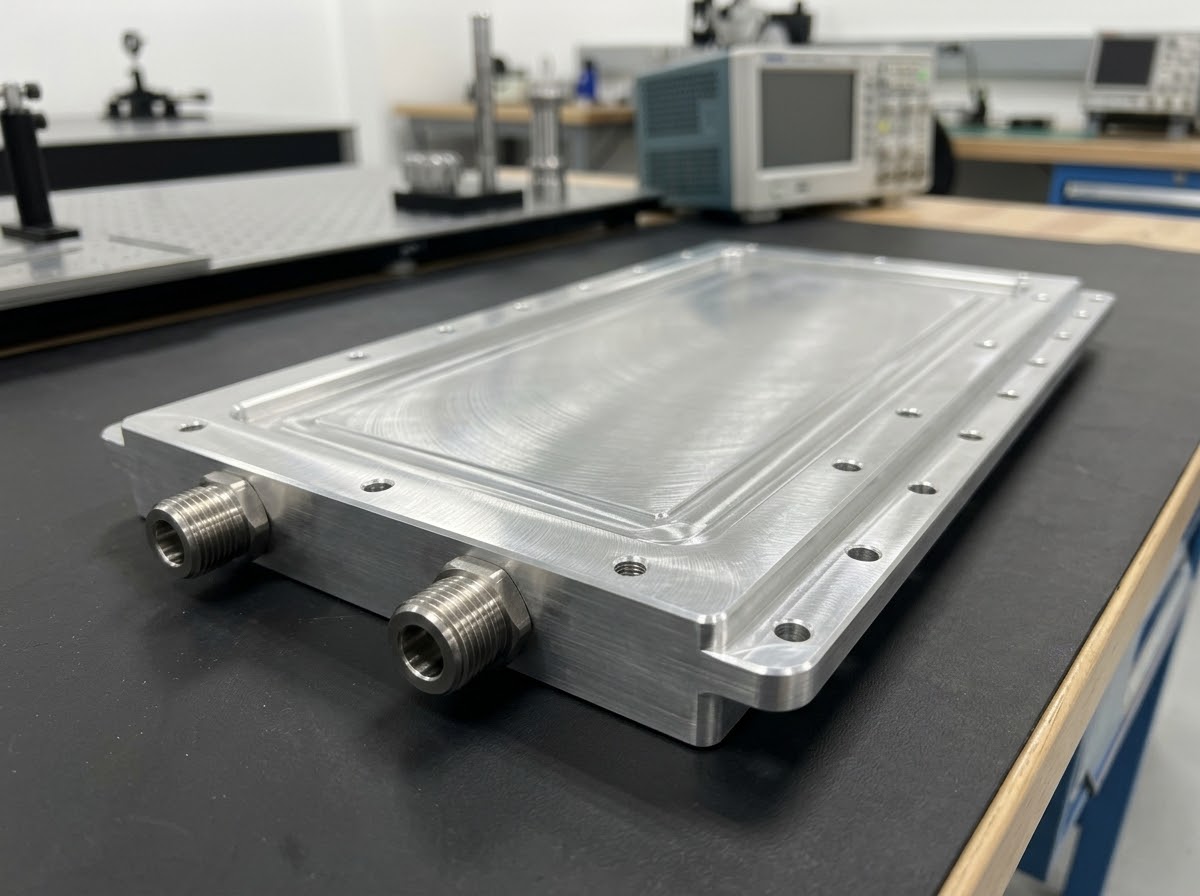
A defined industrial cold plate test specification
- 0.3 MPa rated working pressure
- 0.6 MPa hydraulic proof · 10 minutes
- Final gas leak check after draining and drying
Coolant & materials
Confirm wetted materials, inhibitor package and temperature range together to manage corrosion and long-term compatibility.
Flow & pressure drop
Evaluate base temperature and pressure drop at the same operating point, with the selected coolant—not a water curve alone.
Cleanliness & sealing
Specify internal cleanliness, filtration, port standards, hydraulic proof and final gas leak checks for the approved design.
Mounting & insulation
Control the contact plane, screw loads and TIM; evaluate electrical isolation as part of the power module assembly.
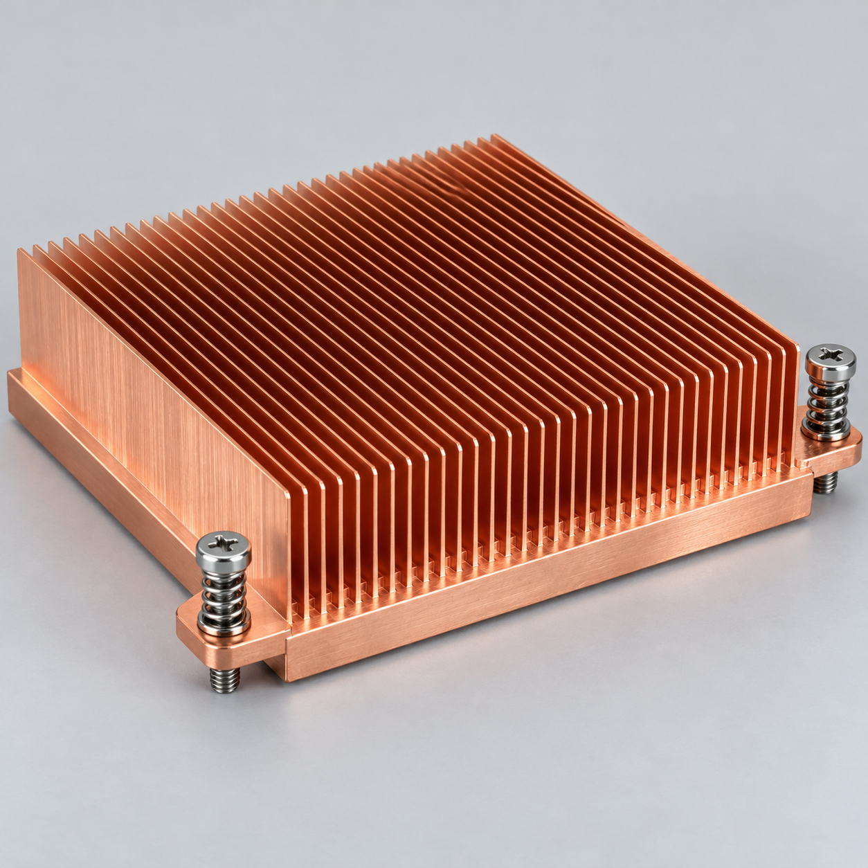
A 12.5 K Gain in a Compact Power Supply
For a German server power supply OEM, a copper skived-fin assembly created more temperature margin within the existing envelope.
Make Qualification Repeatable
Build acceptance criteria around the features that affect power supply performance, assembly and service reliability.
Move From Thermal Brief to a Production BOM
Keep requirements, drawings and test conditions aligned as the project moves from concept to recurring orders.
1 · Share your brief
Provide losses, heat-source footprints, space, inlet conditions and expected annual demand.
2 · Compare & freeze
Review the cooling route, DFM, interface details and the validation plan before releasing drawings.
3 · Validate the sample
Check fit, base temperatures, pressure drop and the agreed reliability requirements in the intended configuration.
4 · Release for production
Approve FAI, process controls, labeling and packaging; maintain drawing and material revision discipline.
Bring these to the first review
Plan the development window
Drawing-based samples: typically 10–20 working days after drawing freeze. Joint heat-pipe, vapor-chamber or liquid development: typically 4–8 weeks for the first sample-and-test loop.
A complete brief makes the first engineering conversation more useful.
Prepare Your Project Brief
Build a More Reliable Power Supply
Share your thermal challenge. Our team will help define a practical heat sink or liquid cold plate route for your equipment.