
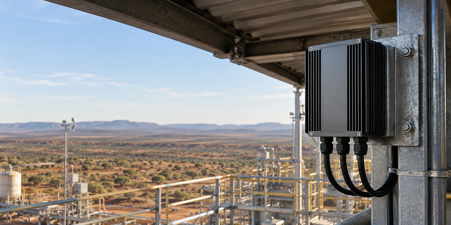
Fanless Heat Sink Enclosure for Outdoor Industrial Gateway
A custom aluminum enclosure moves 35 W of gateway heat into the housing while bringing passive cooling, sealing interfaces and service access into one compact assembly.
A Compact Gateway, Built for a Demanding Site
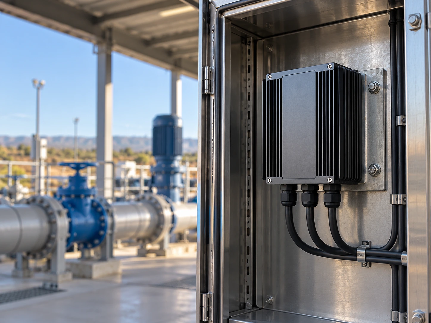
An Australian equipment customer needed a sealed, fanless gateway enclosure for outdoor industrial deployment. The design had to fit a fixed space and remain practical to assemble and reopen.
Four Constraints That Shaped the Design
The challenge was to solve heat flow, environmental protection and mechanical integration together within the same housing.
Heat in a closed volume
Internal air alone could not provide a dependable route for moving device heat into the outside environment.
Passive cooling at 45°C
The fin area and installation direction had to support natural convection without relying on a fan.
Sealing without interruption
End plates, gasket grooves and cable interfaces needed a continuous sealing strategy around the assembled gateway.
Repeatable service access
Mounting points and removable end plates had to support maintenance while preserving the approved assembly configuration.
Align the thermal, sealing and assembly requirements before tooling.
Share Your Design ConstraintsOne Housing. A Defined Thermal Solution
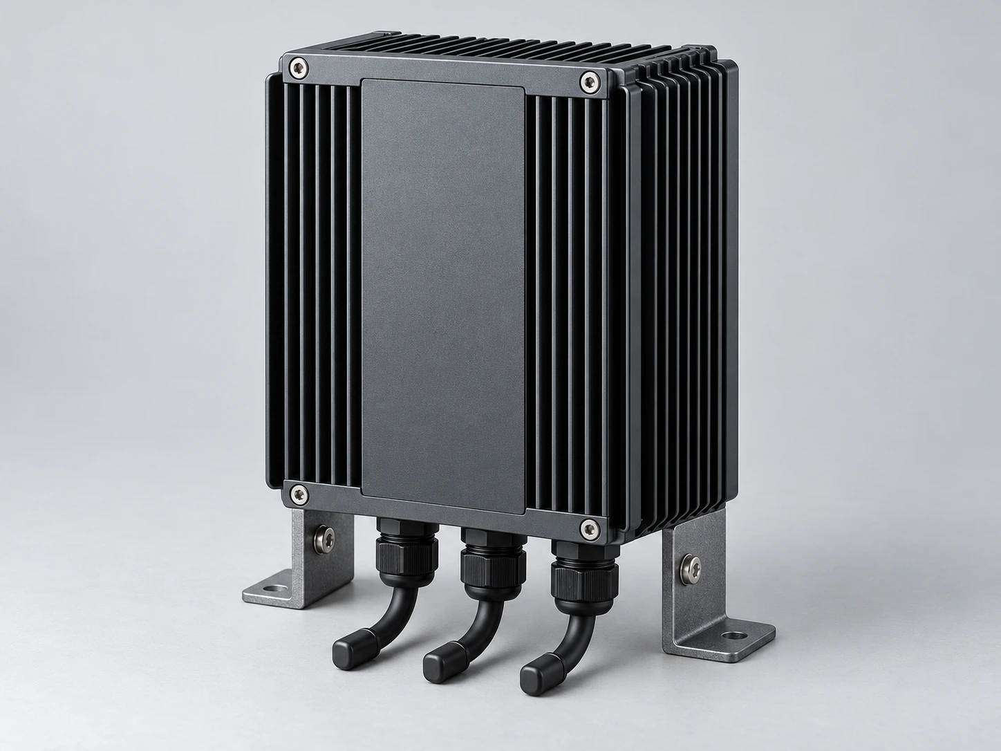
Morton combined a finned aluminum profile, machined end plates and fitted thermal interfaces to make the enclosure itself part of the cooling system.
6063 finned housing
A continuous aluminum profile spreads heat into external sidewall fins and supports passive heat rejection.
6061 end plates
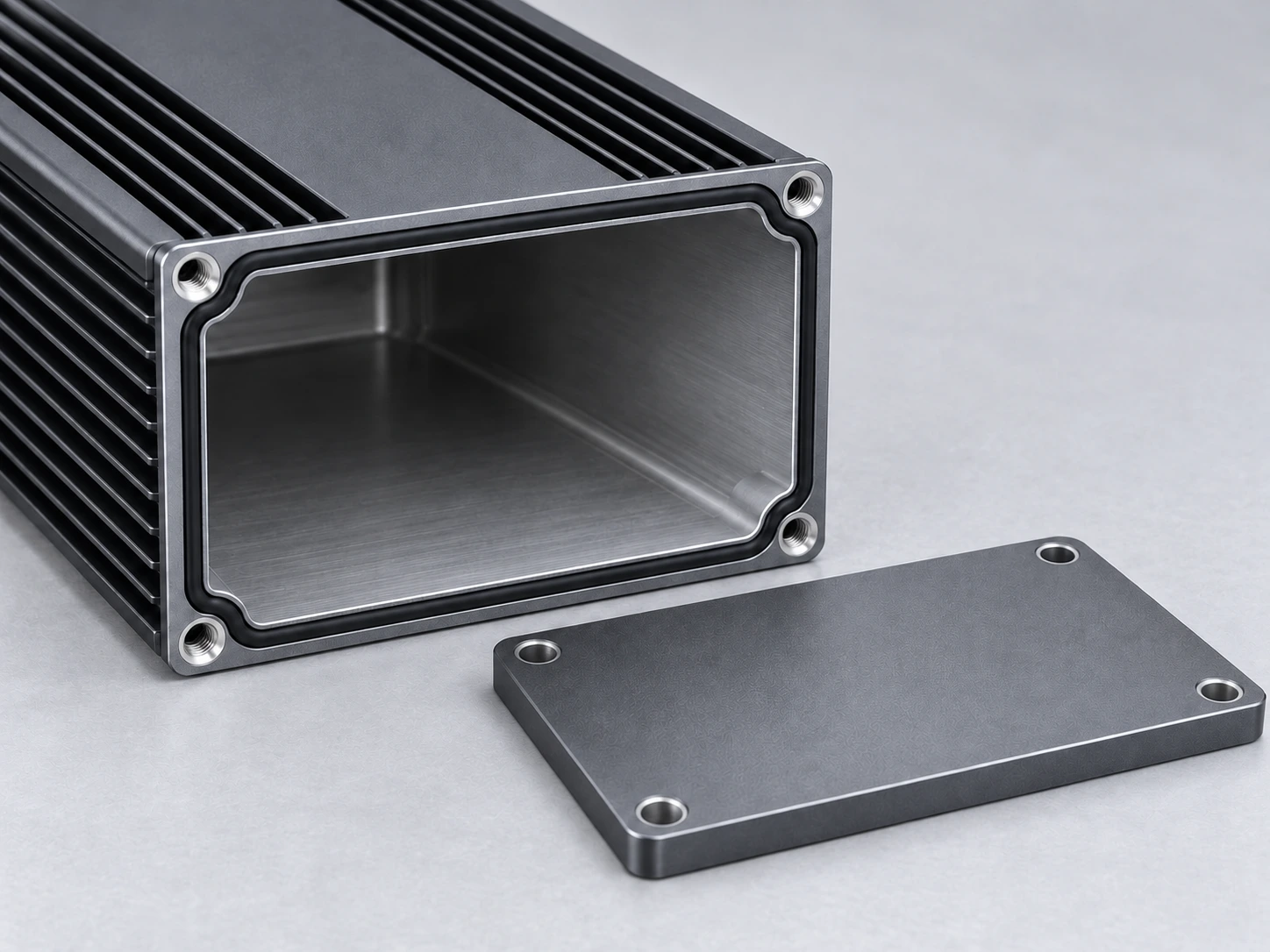
Machined end plates integrate fastening, interface openings and the sealing geometry needed by the gateway.
Thermal pads and mounting points
Selected pads bridge the component-to-housing gap; defined mounting points control the installed relationship.
Need a housing that also works as your heat sink?
Discuss a Custom Heat Sink EnclosureA Continuous Path from the Heat Source to Ambient Air
The design reduces dependence on trapped internal air by creating a deliberate conduction path into the enclosure, followed by natural convection and radiation at the external surfaces.
Heat-source contact block
Collects heat at the defined interface.
Fitted thermal pad
Bridges the assembly gap with controlled contact.
Aluminum enclosure wall
Spreads heat toward the finned sidewalls.
External fins → ambient air
Reject heat in the specified upright installation.
Contact before conductivity
Pad thickness and compression must match the real gap and component load limits. A high conductivity number alone does not define the interface.
Orientation is a design input
Fin channels need a clear vertical convection path. Nearby walls, mounting brackets and direct sun change the operating boundary.
Sealing and Service Access, Designed Together
A sealed enclosure needs more than a closed lid. Morton coordinated the gasket groove, grounding contacts and fastening interfaces around the customer’s complete assembly.
Controlled sealing geometry
The groove and end-plate interface locate the gasket and support repeatable compression during assembly.
Defined grounding contact
Contact areas are specified with the surface treatment so the intended electrical connection can be maintained.
Accessible fasteners and mounting
End-plate screws and installation points remain reachable for planned maintenance and reassembly.
Thermal Results with the Test Conditions in View
The result is tied to the actual heat load, orientation and environment so an engineering team can interpret it against its own device.
| Applied heat load | 35 W |
| Mounting orientation | Specified upright position |
| Air movement | Still-air test bench |
| Solar exposure | Shielded from direct sunlight |
| Measured point | Heat-source contact block |
Need results that relate to your own operating boundary?
Define Your Validation ConditionsFrom 15 Engineering Samples to 600 Enclosure Sets
The project moved from an initial 15-piece sample round to 600 delivered enclosure sets, with the thermal housing and assembly interfaces carried into a controlled production definition.
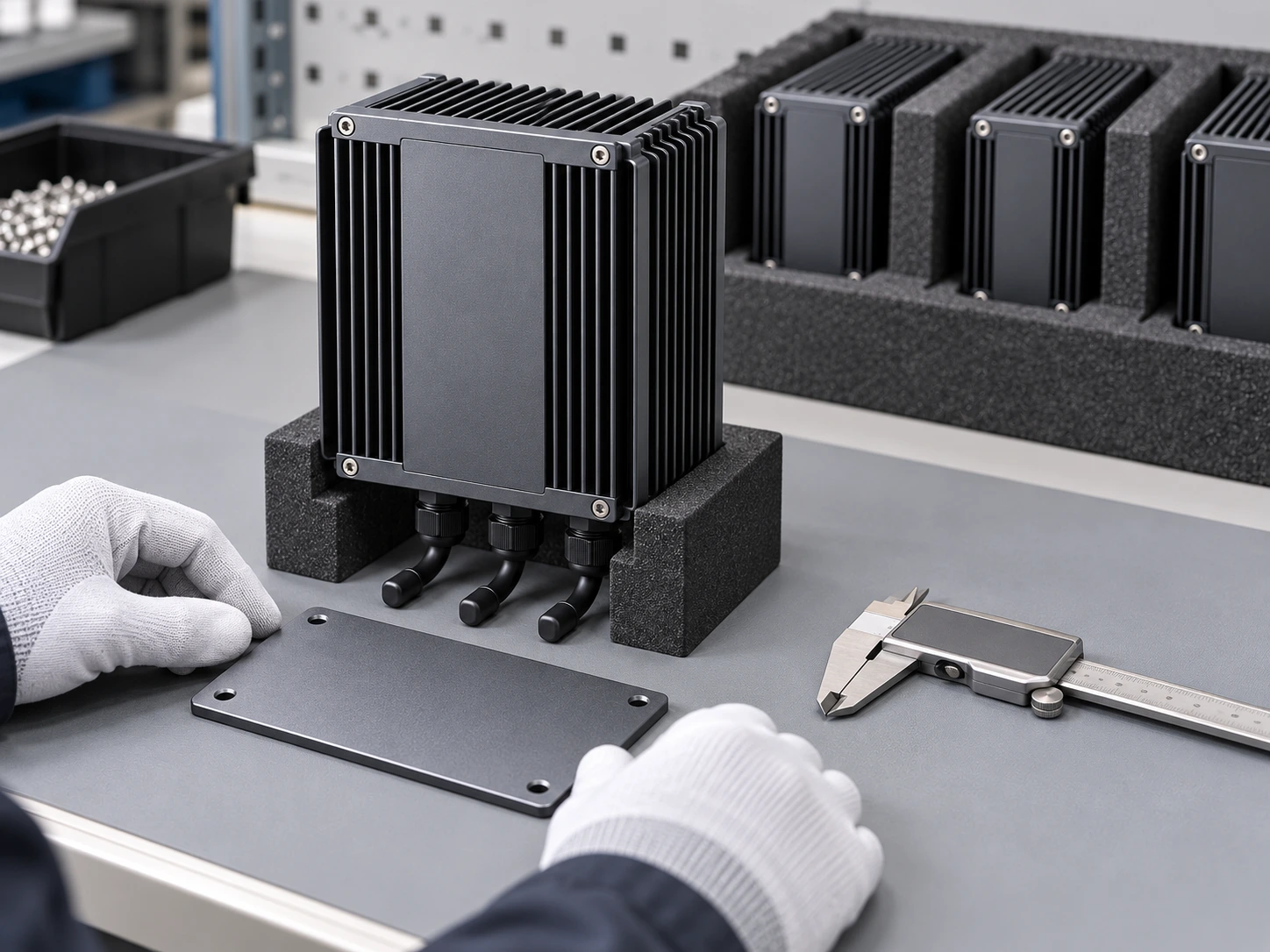
Plan the handover from an approved sample to repeatable supply.
Discuss Samples and ProductionIs This Approach Right for Your Gateway?
A finned enclosure is most useful when the mechanical envelope and installation can support a reliable path from the device’s heat sources to the outside air.
Can this design be used in direct sunlight?
Direct solar loading needs its own assessment. The reported 35 W test was shielded from direct sun; a sunshade, finish or enclosure geometry may need to change for another installation.
Does every enclosure configuration achieve IP65?
Sealing performance belongs to the assembled configuration. Connector selection, gasket compression, end-plate fastening and later reassembly must be validated together.
Can the geometry or thermal load change?
Yes. Heat-source layout, dissipation, ambient temperature and mounting direction are reviewed before a new enclosure size or fin arrangement is selected.
Start with these engineering inputs
- Continuous and peak heat dissipation
- Heat-source positions and contact areas
- Available enclosure envelope and mounting direction
- Ambient range, solar exposure and surrounding clearances
- Connector, sealing and service-access requirements
- Sample quantity and annual demand
Build Your Next Fanless Gateway with Morton
Share the heat load, enclosure space and installation conditions. We’ll help align the thermal path, mechanical interfaces and production requirements.