Stage 01
Engineering samples
Typical first round: 1–5 pieces. Joint heat pipe development commonly takes 4–8 weeks for the first sample and test cycle.

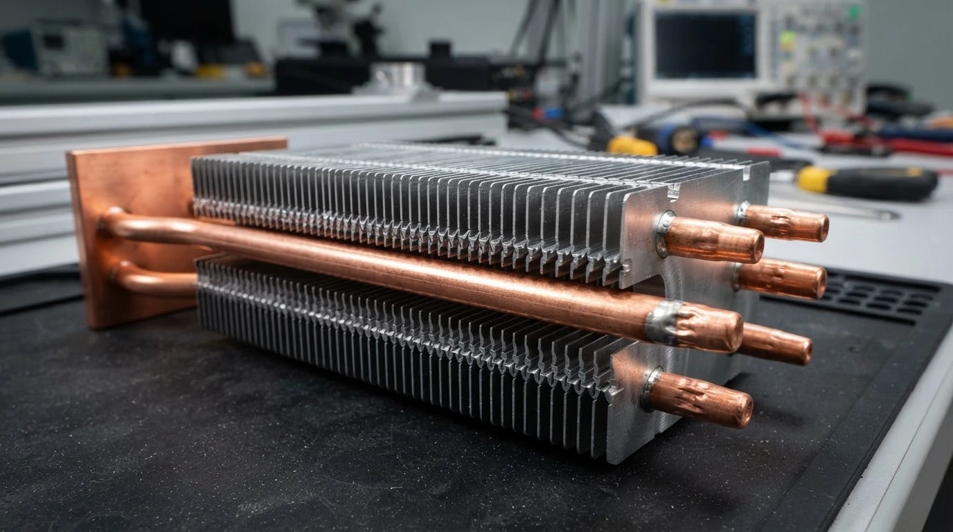
Move concentrated heat to a larger fin area with custom copper-water heat pipe assemblies engineered around your power, airflow and installation constraints.
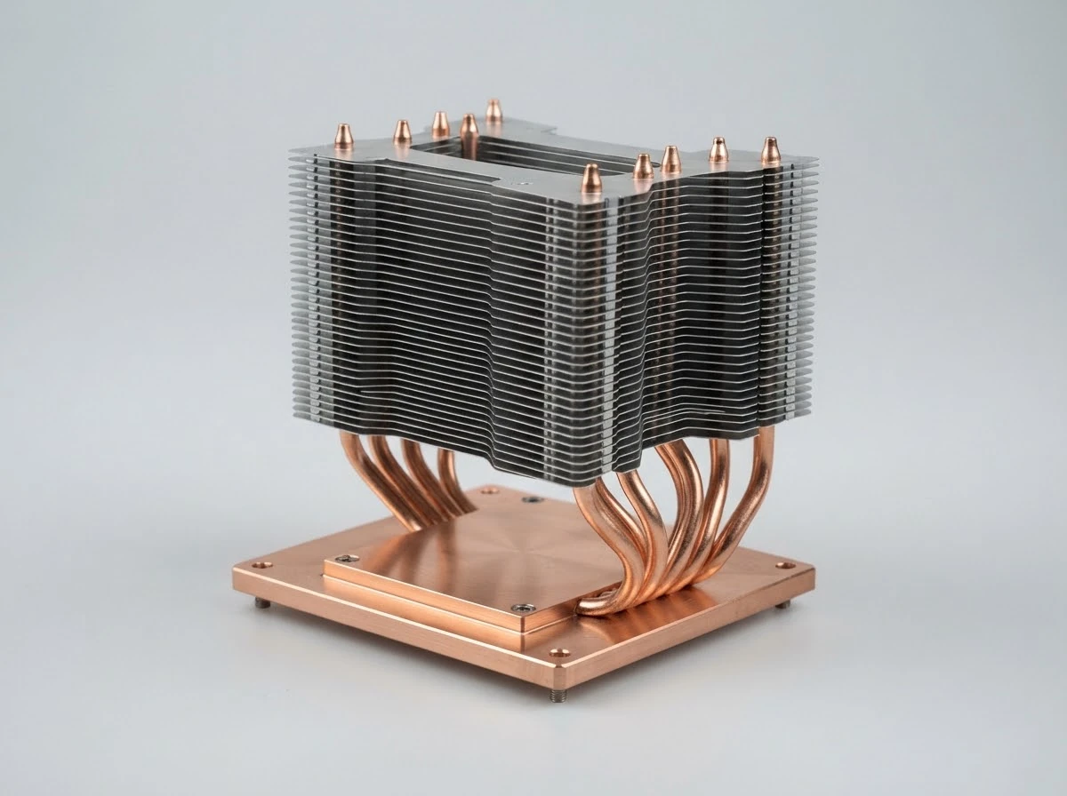
A passive two-phase thermal assembly connects the heat source to a fin stack, spreading heat beyond the footprint of the contact base.
Connect an intense or offset hotspot to the usable cooling area so the fin stack can work more effectively within your enclosure.
Route heat from an obstructed source toward the available air channel.
Distribute energy across the condenser region rather than concentrating it at the base.
Coordinate pipe routing, mounting clearance and fin geometry around the mechanical envelope.
Turn a difficult hotspot into a practical cooling layout.
Map Your Thermal ConstraintsA sealed copper-water heat pipe transports energy through a repeating evaporation and condensation cycle.
Working fluid absorbs heat at the evaporator.
Vapor carries energy toward the cooler condenser.
Vapor releases heat into the fin region.
A sintered wick returns liquid by capillary action.
Design context: Pipe length, working temperature, orientation and geometry affect transport capacity.
Check the heat pipe cycle against your real operating conditions.
Start a Thermal ReviewUse these manufacturing ranges to begin a design discussion, then confirm the combination against the heat load and installation conditions.
| Design Item | Typical Range | Engineering Consideration |
|---|---|---|
| Pipe outside diameter | 4 / 6 / 8 / 10 mm | Select with heat load and routing constraints. |
| Pipe length | 80–500 mm | Transport capacity changes with length and posture. |
| Assembly envelope | 60–350 × 60–400 × 20–120 mm | Dimensions are L × W × H. |
| Pipe construction | Copper-water, sintered wick | Validate at the intended operating temperature. |
| Common steady-state temperature | About 30–110 °C | Assess startup and cold conditions separately. |
Share your available envelope and operating temperature.
Check Design Feasibility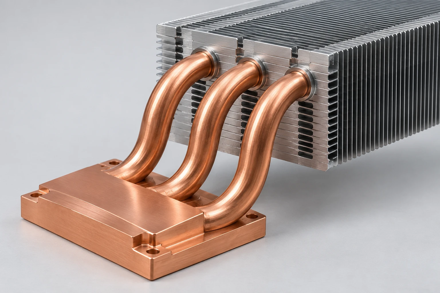
Pipe geometry and condenser placement connect the contact zone to the available fin area while respecting the enclosure.
Make routing decisions before they become tooling changes.
Review Your Assembly LayoutA heat pipe moves energy to the fin stack; the final cooling result still depends on the air that actually passes through it.
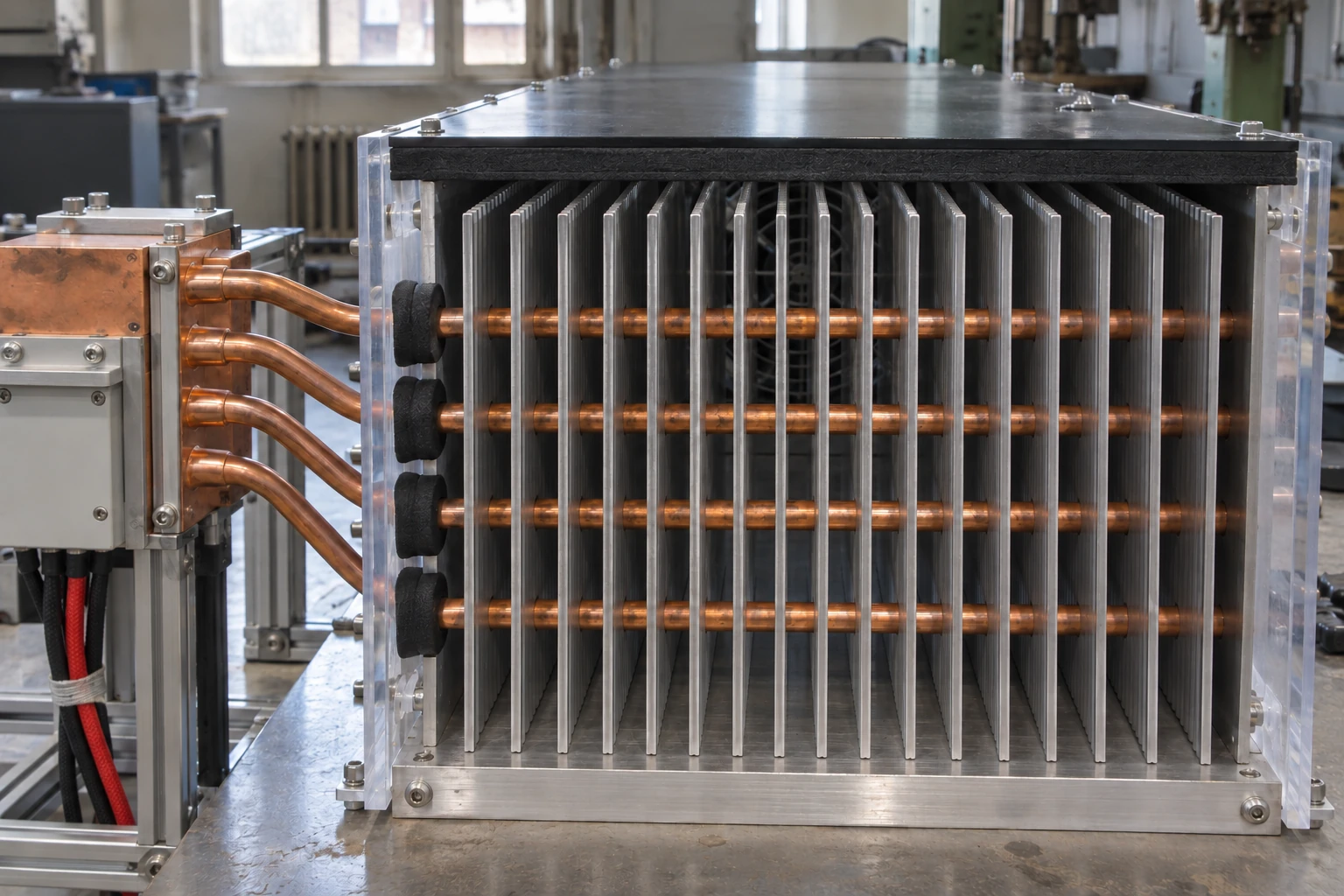
Balance heat-transfer area with fan pressure and dust exposure.
Use the pressure-flow curve and duct resistance together.
Guide air through the active fin channels and assess enclosure leakage.
The contact surface, interface material and pipe-to-fin connection work together to determine how reliably heat reaches the air.
Coordinate flatness, mounting force and TIM thickness with the device limits.
Control contact geometry, joining material and assembly positioning.
Maintain a consistent bond across the condenser region.
Check mechanical retention, vibration and thermal expansion for the installation.
Apply a tailored heat-transfer path where electronics need more cooling area than the hotspot footprint can provide.
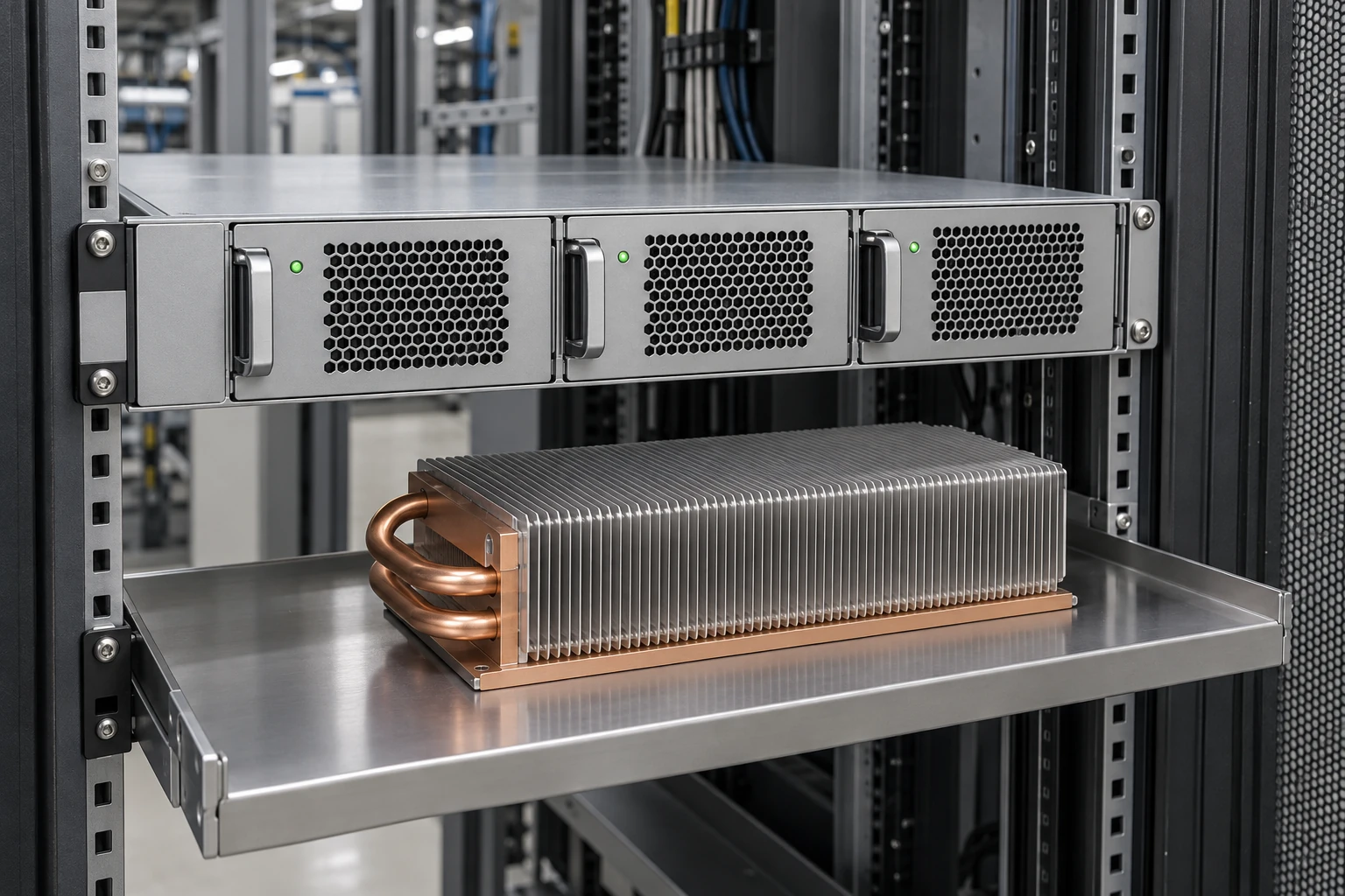
Move offset power losses into the available rack airflow.
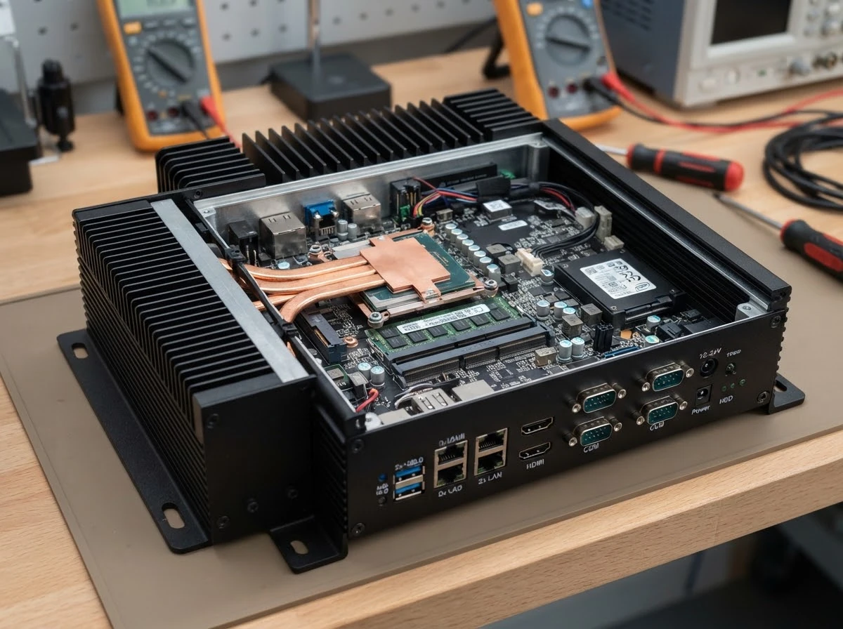
Connect concentrated processors to constrained fin locations.
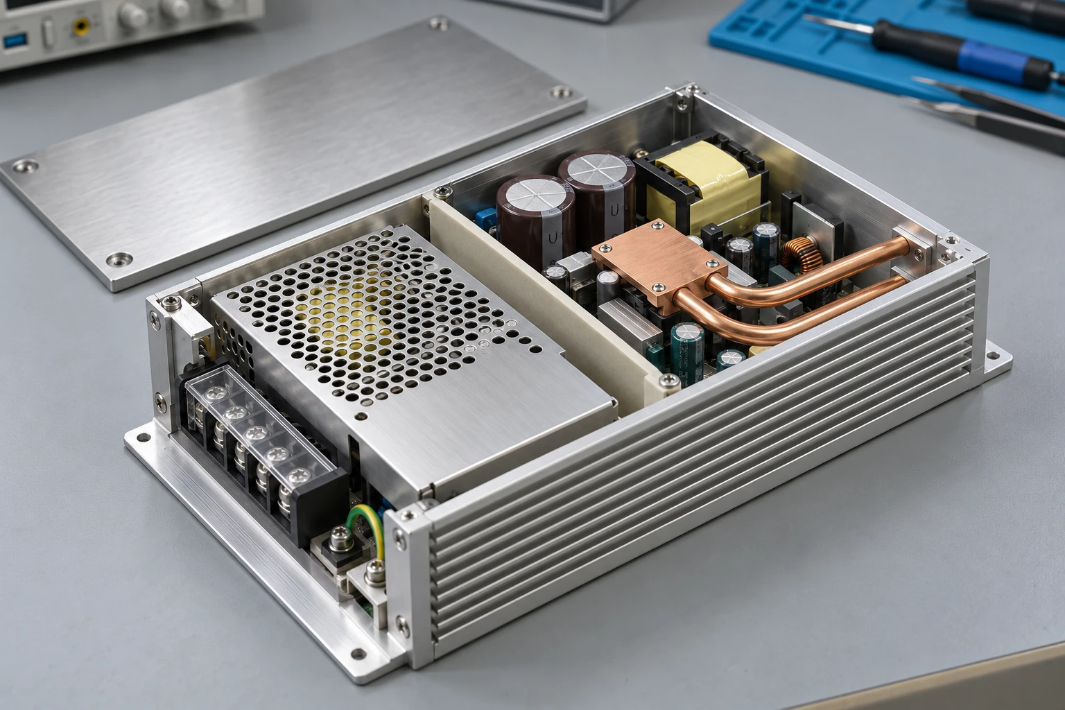
Spread local power-device heat across a larger fin stack.
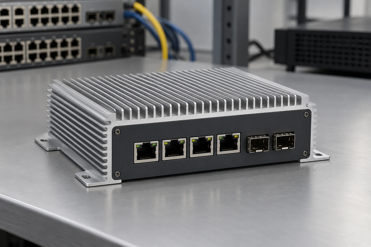
Coordinate multi-source heat paths inside compact enclosures.
A Singapore telecom power project connected a 60 × 60 mm hotspot to a 200 × 250 mm fin region using eight 8 mm copper-water heat pipes.
Hotspot-to-inlet-air thermal resistance
| Heat Load | 450 W |
| Inlet Air | 25 °C |
| Installed Airflow | 220 m³/h |
| Assembly Envelope | 200 × 250 × 80 mm |
| Installation | Design installation posture |
7 weeks from samples to approval under mutual test protocol.
500-piece first delivery fulfilled on schedule for system pilot.
Vibration and −20 to 80 °C thermal-cycle screening under agreed procedure.
A shared drawing and validation process keeps the heat pipe route, interfaces and acceptance criteria aligned from the first sample to repeat production.
Confirm power map, source area, temperatures, airflow, space and posture.
Coordinate base, pipe routing, fin stack, mounting and DFM.
Test the first assembly at the agreed load, airflow and posture.
Freeze approved drawings, process controls and inspection records.
Keep engineering decisions connected to production requirements.
Plan Your Development ProcessIncoming heat pipe screening, controlled joints and defined thermal tests help maintain the approved assembly through repeat orders.
Check thermal response or transport consistency against the controlled specification.
Inspect mounting features, pipe positions, fin condition and contact surfaces.
Define source geometry, load, inlet temperature, airflow, posture and measurement locations.
Link drawings, material batches, work orders and inspection records; manage critical changes through ECN.
Put measurable acceptance criteria into your drawing package.
Discuss Quality and ValidationStart with engineering samples, establish a validated production configuration and scale with clear drawings, commercial terms and delivery planning.
Typical first round: 1–5 pieces. Joint heat pipe development commonly takes 4–8 weeks for the first sample and test cycle.
Heat pipe assemblies typically begin at 20–50 pieces, depending on design complexity and tooling.
Typical production lead time: 30–45 days after drawings, sample approval, order and payment conditions are met.
Share your forecast and drawing maturity for a realistic supply proposal.
Request a Project QuotationClarify the design inputs that matter before selecting pipe quantity, fin geometry and the validation plan.
Bring the remaining questions to an engineering discussion.
Ask About Your Design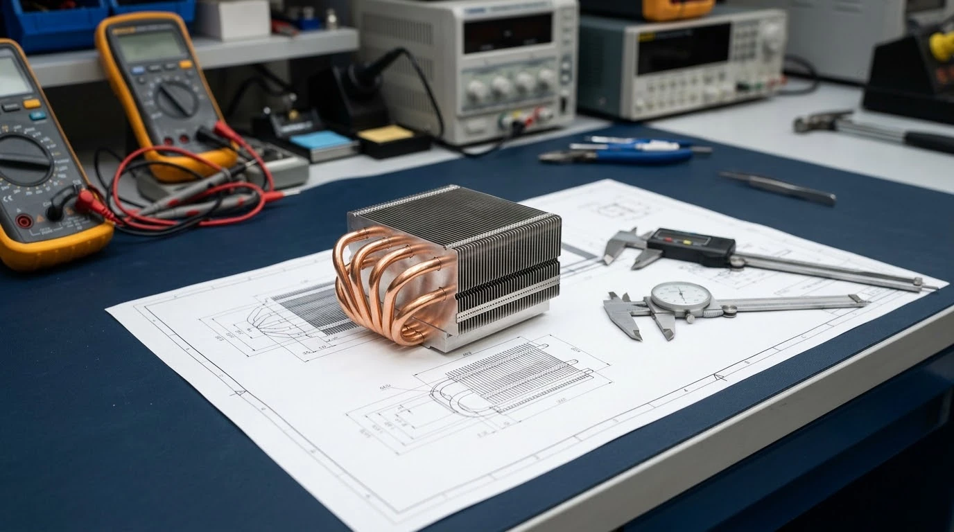
Tell us where heat starts, where it needs to go and how your equipment operates. We will help define the next engineering step.