
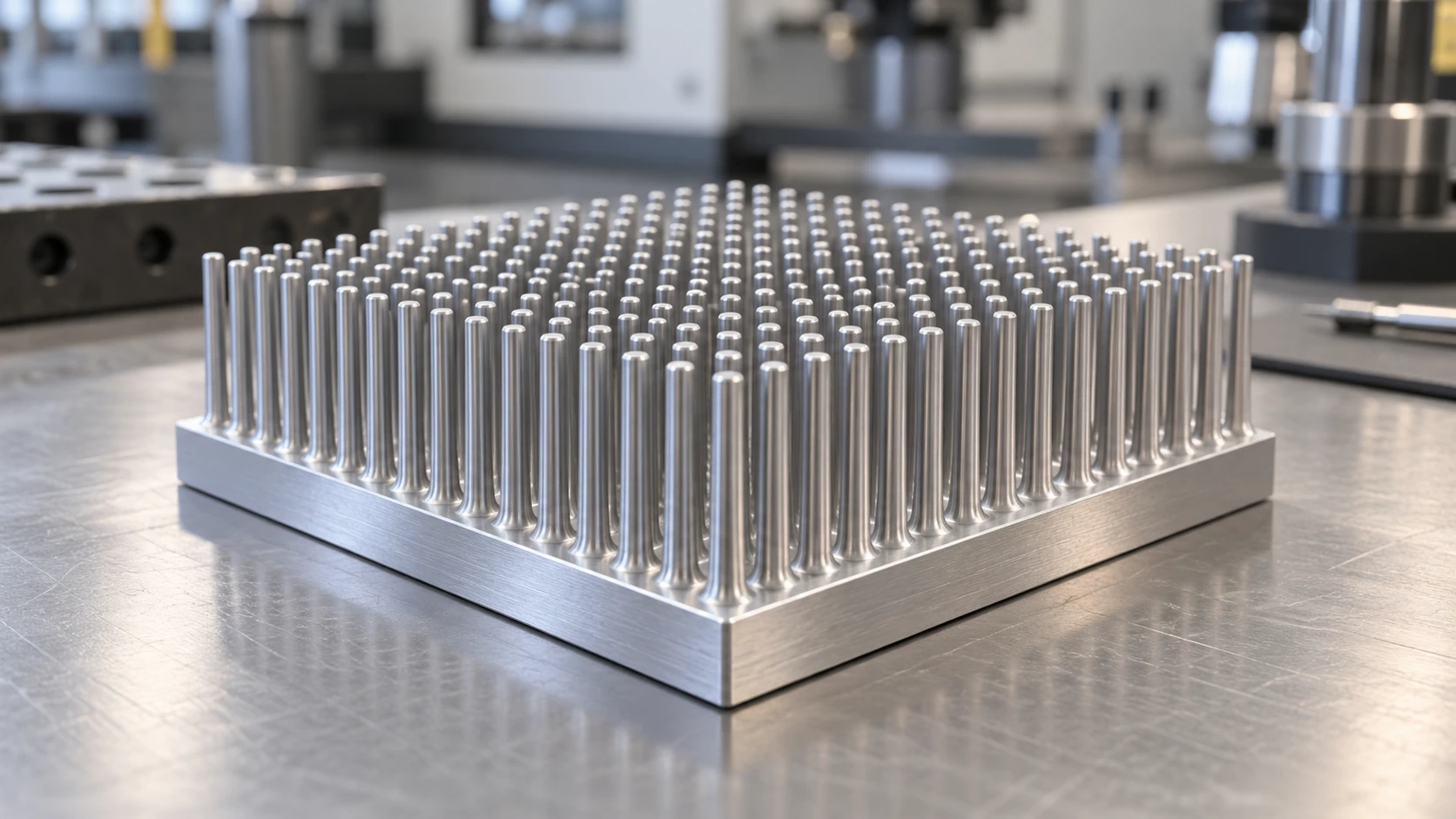
Cold Forged Heat Sinks
One-piece pin-fin cooling, engineered around your heat source, airflow and production requirements.
Bring your thermal limits into the first design review.
Discuss Your Cold Forged Design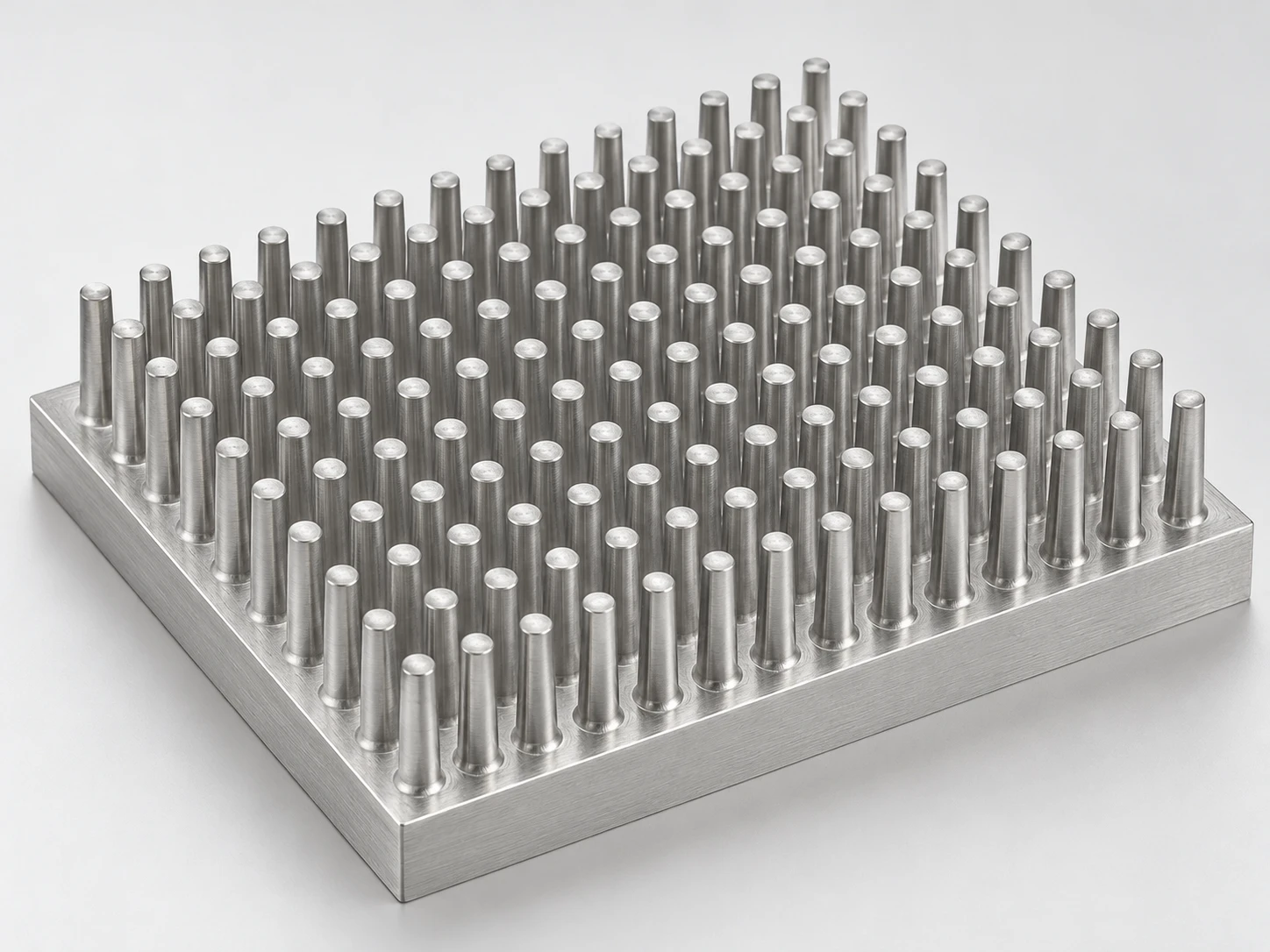
What Is a Cold Forged Heat Sink?
Cold forging forms the base and pins from one metal blank. A continuous metal path carries heat from the mounting face into an array of cooling pins.
See how a forged structure can fit your assembly.
Review My Product ConceptA Compact Structure with Practical Advantages
Combine a direct conduction path with a pin layout that respects your enclosure, mounting position and airflow.
Continuous conduction
A monolithic base-to-pin structure removes the extra fin-to-base bond layer.
Airflow flexibility
Pin arrays support cooling when air direction changes across the equipment.
Compact integration
Base thickness, pin field and mounting features are developed around available space.
Repeatable supply
Approved tooling and inspection criteria keep recurring orders aligned with the drawing.
Turn these benefits into a geometry your equipment can use.
Explore My Design OptionsKeep the Thermal Path Continuous
A solid connection between base and pins helps heat spread into the cooling surface. Interface quality and airflow still determine the temperature your device reaches.
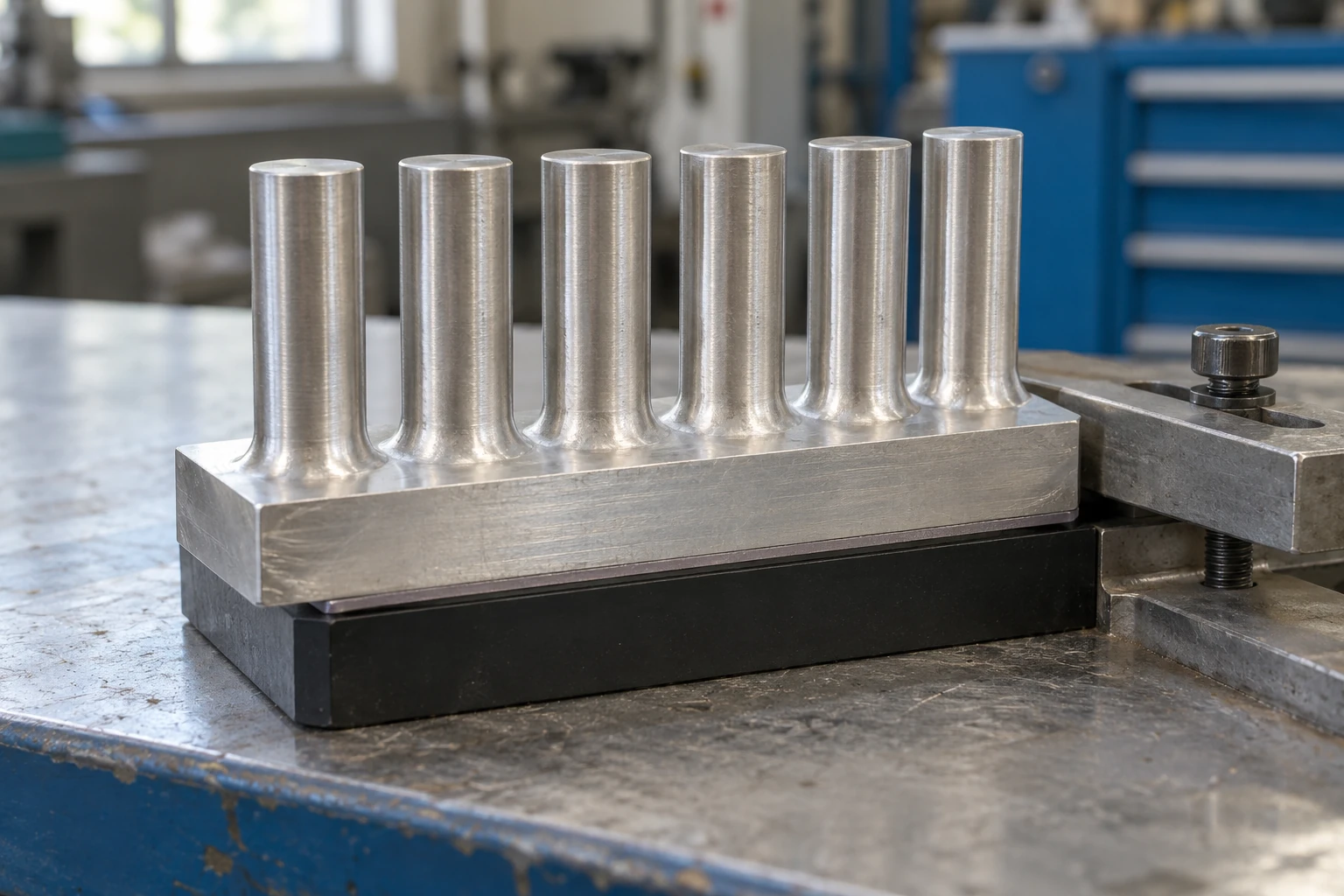
Optimize the full thermal path, from device contact to outlet air.
Review My Thermal PathMatch the Pin Field to the Airflow
Pin density is a design variable. Open passages, usable surface area and fan pressure must work together.
Natural Convection Regime
Buoyancy-driven open channel geometry
-
Keep clear inlet and outlet paths: Preserve unrestricted entry from base level and ample headroom above pin tips.
-
Check the installed orientation: Align open thermal avenues with gravitational vertical escape routes for warm air.
-
Avoid boundary layer crowding: Wider pin spacing prevents adjacent thermal boundary layers from choking buoyant air flow.
Forced Airflow Regime
Pressure-driven, boundary layer renewal
-
Use the installed fan operating point: Design pin pitch directly against static pressure and real volumetric delivery curves.
-
Review bypass leakage and pressure drop: Shroud or calculate overhead gap leakage to prevent forced air bypassing the core matrix.
-
Confirm flow reaches the hot region: Ensure high-velocity air actively penetrates dense center pins rather than deflecting around outer pins.
Share the enclosure and fan arrangement for a focused airflow review.
Discuss Airflow & Pin SpacingChoose the Metal Around the Job
Material selection balances conductivity, weight, formability and total part cost. Surface treatment follows the contact and environmental requirements.
1050 / 1070 Aluminum
A light, formable option for pin-fin structures where mass, tooling feasibility and production cost matter. Offers excellent forging flow rates and solid thermal performance for weight-sensitive enclosures.
C1100 Copper
Higher thermal conductivity supports heat spreading in compact designs where the added mass and cost are justified.
Controlled Surface Finishing & Environmental Protection
Natural finish
A clean metallic surface for straightforward integration. Degreased and deburred for immediate baseline thermal contact in clean enclosures.
Anodizing for aluminum
Color and film requirements are defined on the drawing. Provides surface durability, corrosion resistance, and increased radiative emissivity.
Nickel plating for copper
Specify coating thickness and contact requirements together. Nickel plating can limit copper oxidation; verify contact resistance and solderability for the selected coating and joining process.
Selective masking
Keep specified thermal contact faces, threads and grounding areas free of coating. Verify final flatness and electrical contact against the drawing and assembly requirements.
Compare material and finish choices before the tool is frozen.
Request a Material ReviewA Clear Starting Envelope for Your Design
Start with our regular cold-forging range, then review the combined pin diameter, effective height and base geometry for your part.
| Effective pin height | 10–40 mm |
|---|---|
| Fine-pin geometry | 1.5 mm pins: typically up to 20 mm effective height |
| Tooling review | Material flow, draft, pin filling and ejection |
| Final definition | Approved drawing and process review |
Send your envelope and heat-source footprint for a practical DFM review.
Check My GeometryBuild the Mounting Interface into the Design
A heat sink only performs as intended when the device, thermal interface material and fasteners form a controlled assembly.
Mechanical & Precision Machining Datums
Machine and inspect the device contact area against the approved datum scheme.
Locate mounting features from functional datums, with coating allowance included.
Reserve space for drivers, fasteners, wiring and assembly tools.
Thermal Path & Assembly Loading
Match the interface to flatness, surface texture and the real assembly gap.
Set screw torque or spring force around device and PCB load limits.
Verify dimensions after machining and surface treatment.
Resolve contact and mounting details before they become assembly issues.
Review My Mounting InterfaceFrom Metal Blank to Production Part
Morton coordinates qualified forging partners with controlled machining, inspection and release, giving your team one accountable project contact.
01 · Feasibility & Tool Review
Confirm material, pin geometry, forming feasibility, ejection and drawing requirements.
02 · Material Verification
Check the specified alloy, incoming condition and batch identity.
03 · Cold Forging
Form the base and pins using approved tooling and a controlled partner process.
04 · Secondary Machining
Finish the contact face, holes, threads and functional datums.
05 · Finish & Inspection
Apply the specified surface treatment, verify critical dimensions and inspect the pin field.
06 · Approved Release
Release against the drawing, inspection plan and agreed packaging requirements.
Bring tooling, machining and inspection into one controlled plan.
Discuss My Manufacturing PlanWhere Cold Forged Cooling Fits
Cold forged pin-fin heat sinks suit products where a compact conduction path and accessible air passages support the cooling strategy.
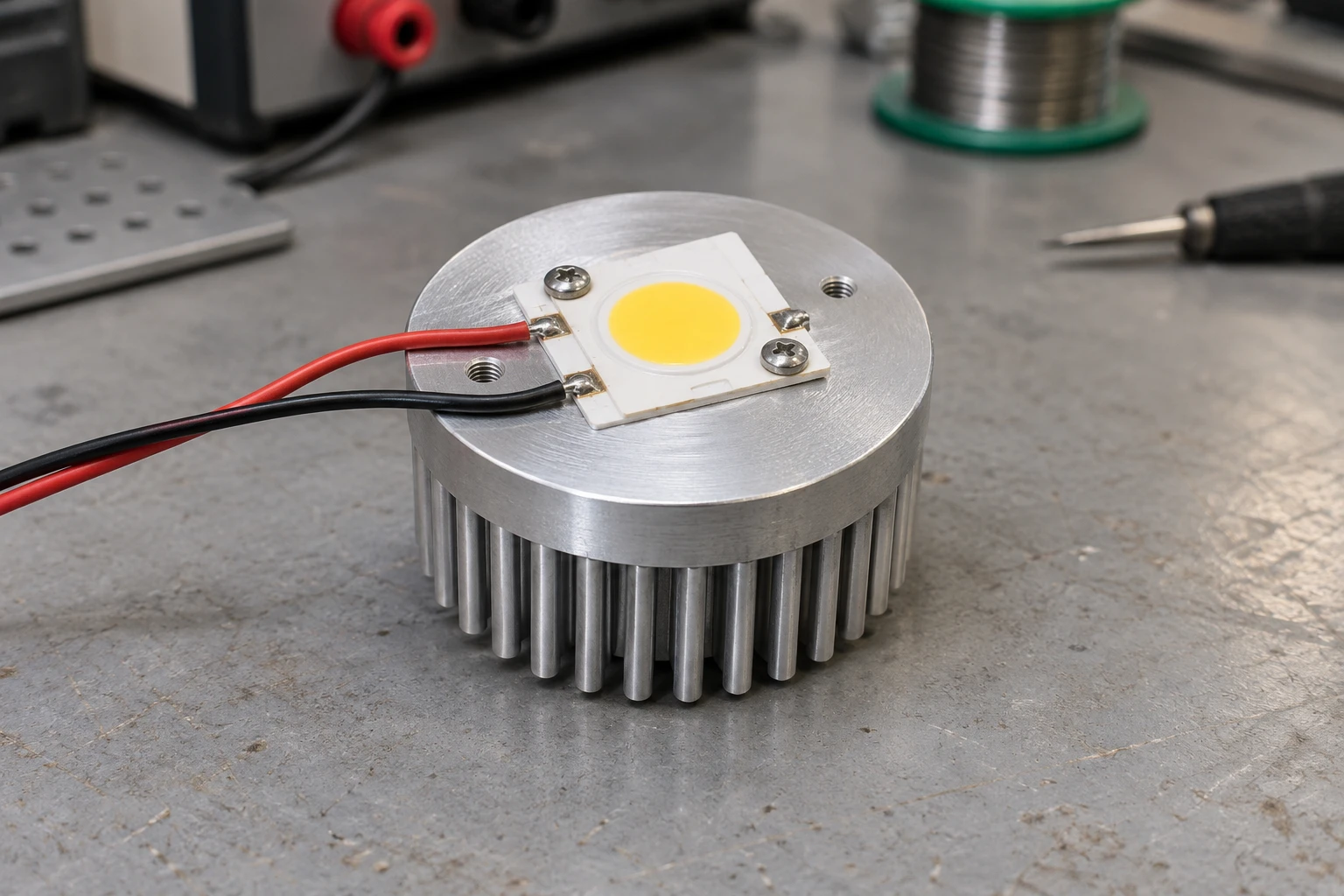
COB LED Lighting
Spread heat from a compact light engine into a pin field while preserving airflow around the fixture.
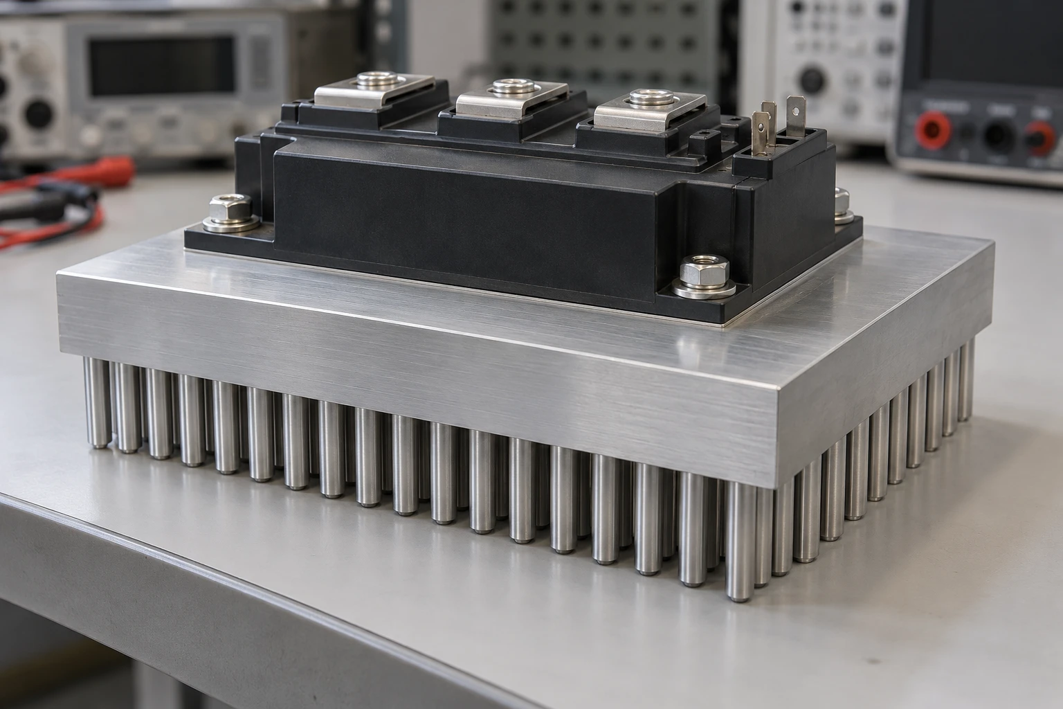
Power Electronic Modules
Combine a finished device contact face with mounting features for compact power conversion assemblies.
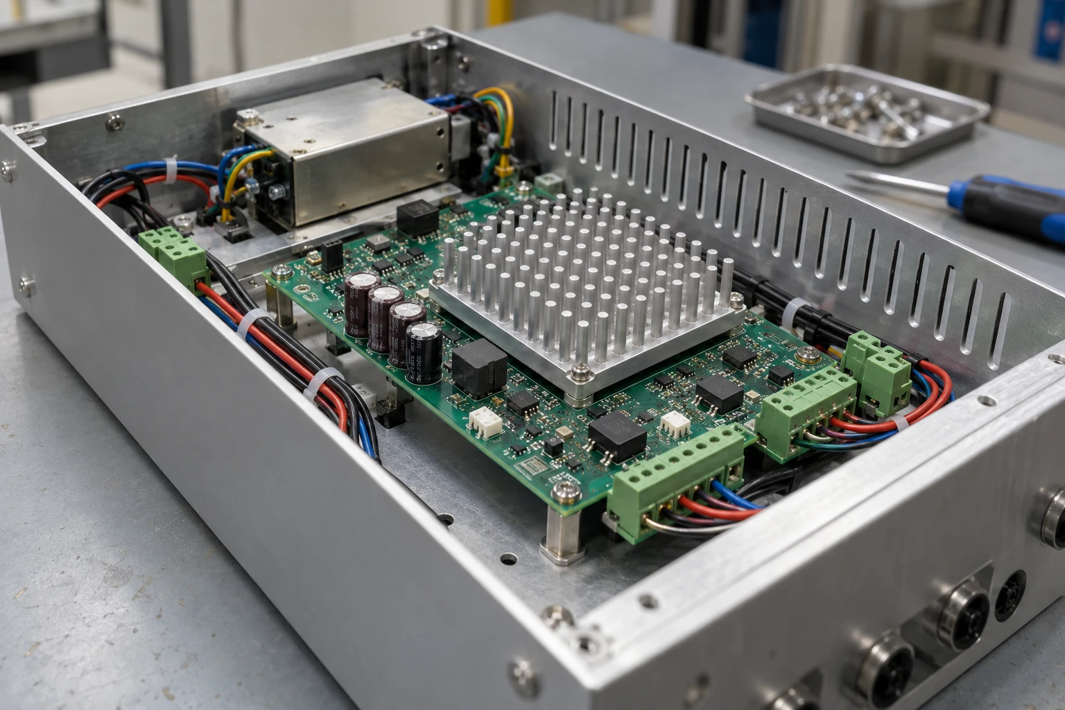
Industrial Control Electronics
Fit the cooling geometry around enclosure vents, wiring and equipment installation constraints.

Telecom & Embedded Equipment
Support localized heat removal where packaging and changing airflow call for a tailored pin layout.
Explore application feasibility for your specific thermal and enclosure envelope.
Discuss Your ApplicationValidate Performance in the Real Conditions
A useful thermal result starts with defined heat input, inlet air temperature, installed airflow and measurement positions.
Get a test plan that reflects how your equipment actually operates.
Plan My Thermal ValidationQuality Evidence Your Team Can Review
Connect the approved drawing to the delivered batch with material, dimensional and inspection records.
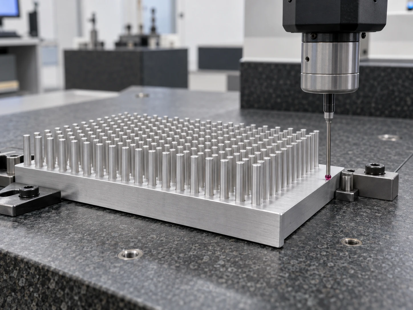
Material identity
Alloy verification and batch records support traceability.
First-article inspection
Check drawing features, pin geometry and the finished mounting interface.
Controlled changes
Review tooling, material and process changes before implementation.
Delivery records
Provide CoC, inspection records and project-specific compliance documents.
Align the evidence package with your engineering and supplier quality reviews.
Discuss My Quality RequirementsPlan Tooling, Quantity and Repeat Supply Together
A realistic cold-forging quotation accounts for tooling, approved geometry, validation quantity and the production forecast.
Tooling & First Article
New tooling and first-article approval commonly take 4–8 weeks, depending on complexity and review milestones.
Economic Production Quantity
New-tool cold-forged parts typically start at 500–1,000 pieces; final economics depend on geometry, alloy and tooling.
Repeat Supply
Released tooling and drawings support scheduled batches, revision control and agreed protective packaging.
2D drawing or 3D model, material, finish, heat load, available airflow, annual demand and target timing.
Quotation separates tooling, part cost, machining, finish, inspection and packaging for complete procurement clarity.
Share the forecast early to make tooling and unit cost work together.
Request a Project QuotationCold Forged Heat Sinks: Your Questions Answered
Practical answers for engineering, purchasing and supplier quality teams evaluating a cold forged design.
Is cold forging suitable for every pin geometry?
Does a pin-fin layout work in every orientation?
Can you add holes, threads and a precision contact face?
How do aluminum and copper compare?
What should we provide for a thermal evaluation?
What information is needed for a quotation?
Have a drawing or an installation constraint to discuss?
Ask Our Engineering Team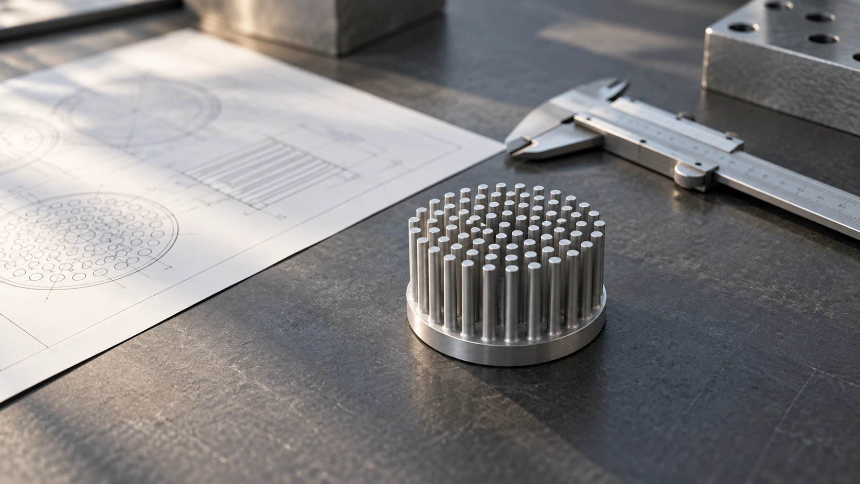
Start Your Cold Forged Heat Sink Project
Tell us what your device needs to dissipate, how much space is available and how the air moves. Morton will help define a manufacturable path from concept to approved supply.
Request Engineering Review
Share your thermal & space constraints with our technical team.