Build Your Thermal Solution with Morton

Air & Liquid CoolingHeat sinks, heat pipe assemblies and liquid cold plates for industrial equipment.
Engineering Around Your NeedsMatch your heat load, space, mounting and operating conditions.
Traceable QualityDrawing revisions, inspection records and agreed acceptance criteria.
From Samples to SupplySupport for development samples, project orders and repeat production.
A Clear Next StepYour inquiry receives a response within one working day.

Start Your Thermal Project

Share your request below. We will respond within one working day to clarify your needs and the next step.

Optional. Choose a country, or enter a full number starting with +.

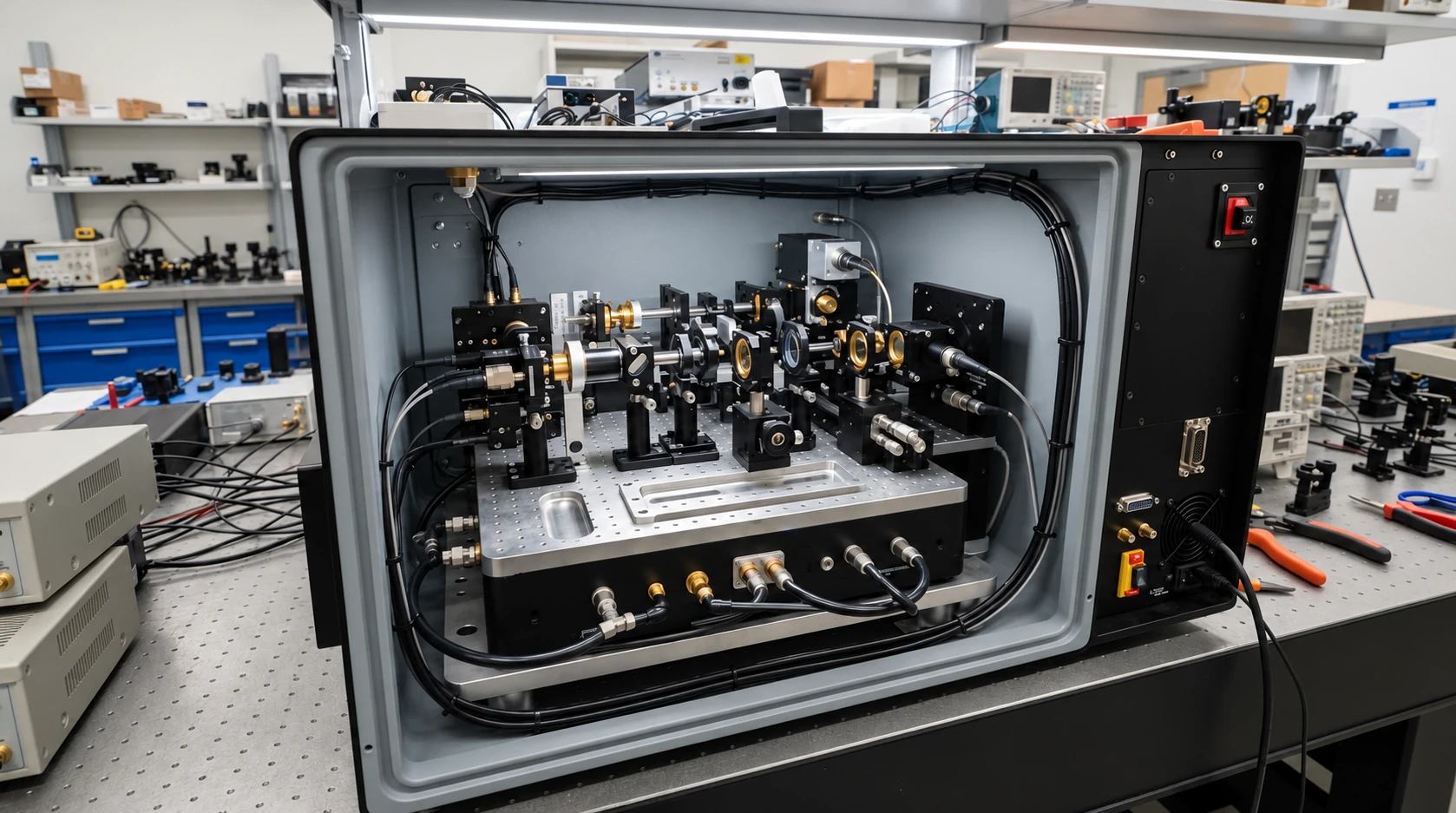
Optical equipment opened for inspection on an engineering bench
LASER & PRECISION EQUIPMENT

Thermal Stability for Laser & Precision Equipment

Custom cold plates and precision heat sinks manage waste heat at the source, helping laser and precision equipment maintain repeatable performance through long operating cycles.

Build thermal control into your next equipment platform.

Discuss Your Thermal Requirements

Small Temperature Changes. Real Production Consequences

In laser and precision equipment, a thermal issue can become a process issue long before a component reaches its temperature limit.

Wavelength & Output Drift

Changing diode temperature can shift wavelength and output, making a stable operating point harder to maintain.

Thermal Distortion

Uneven expansion across mounts and baseplates can disturb alignment and dimensional repeatability.

Localized Hotspots

Concentrated losses in diode drivers, pump modules and control electronics can limit duty cycle.

Coolant & Leak Risk

Particles, incompatible materials and weak connections can turn the cooling loop into a reliability risk.

Start with the thermal issues that affect your process.

Review Your Thermal Challenges

Engineer the Entire Path from Heat Source to Coolant

A capable cold plate only works as part of a controlled thermal path. We connect heat-source layout, mounting mechanics and the available cooling conditions.

Capture the actual load
Define continuous and peak losses, heat-source footprint and duty cycle.
Control the contact
Review flatness, interface thickness, clamping force and differential expansion.
Match the heat rejection
Size channels or fins against coolant flow, pressure drop or installed airflow.
Controlled Thermal Chain Architecture
01
Heat source
Laser Diode / Driver
02
Thermal interface
Flatness & TIM Gap
03
Heat spreader
Copper / aluminum base
04
Cold plate / fins
Precision Channels
05
Coolant / air
Loop Heat Rejection
Review every interface against the same operating conditions.

Give us your heat-source map and available cooling conditions.

Map Your Thermal Path

Cooling Matched to Your Laser & Precision Platform

Different equipment architectures create different thermal constraints. We tailor the component around the heat source, installation space and process environment.

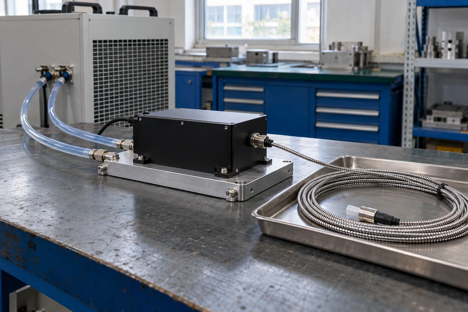
Sealed fiber laser module fixed to a liquid cold plate with separate coolant hoses

Fiber Laser Pump Modules

Spread concentrated pump-diode losses across a defined cooling footprint while preserving access to mounting and fluid connections.

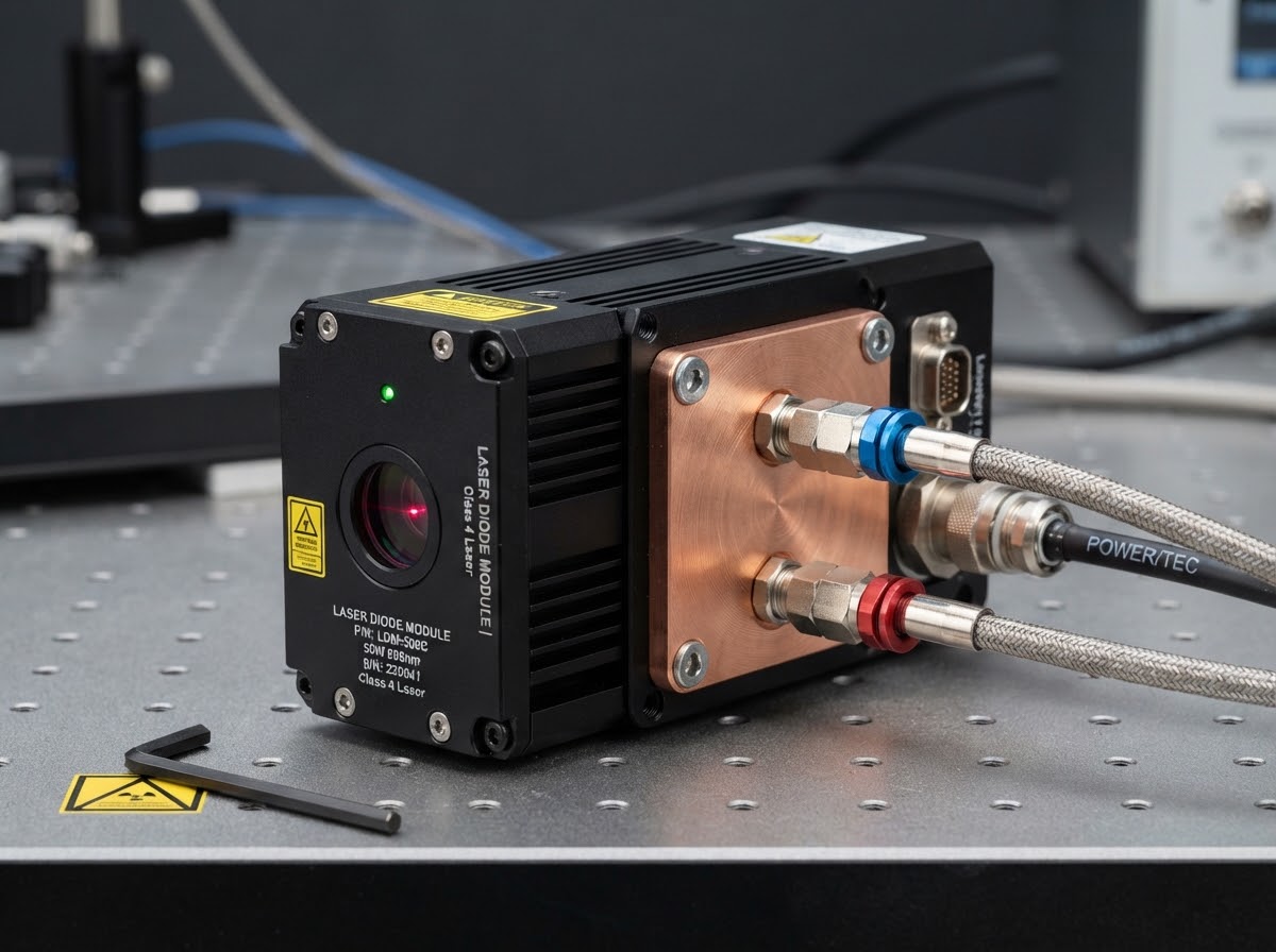
Compact enclosed diode laser assembly with copper heat spreader and paired coolant connections

Diode Laser Assemblies

Combine a stable contact surface with a controlled coolant path for compact, temperature-sensitive diode modules.

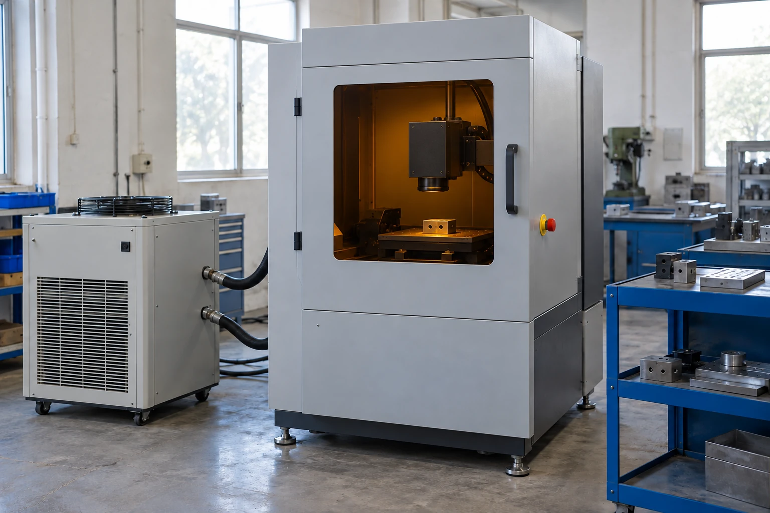
Enclosed laser micromachining station connected to a recirculating cooler

Ultrafast Micromachining Systems

Manage heat around laser sources, drivers and motion electronics without obstructing the precision assembly.

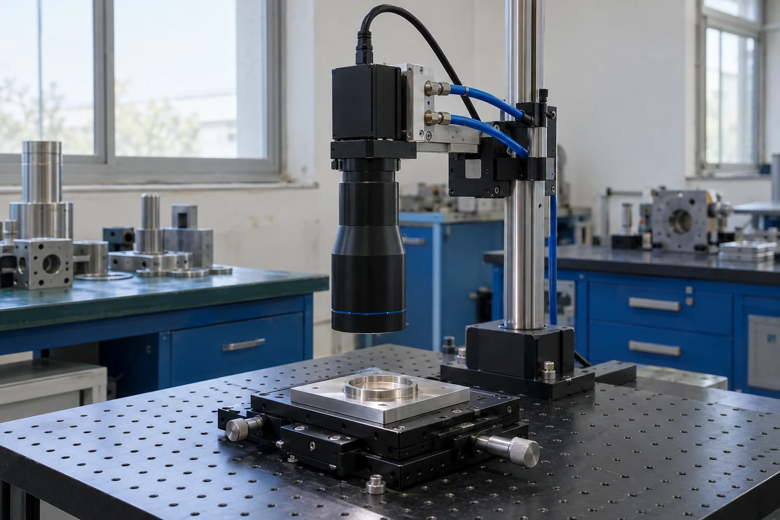
Precision camera on a liquid-cooled mounting bracket above a translation stage

Optical Inspection & Metrology

Route heat away from sensitive mounts and electronics to reduce thermally induced movement near the measurement path.

Tell us where heat is disturbing your equipment performance.

Find Your Application Fit

Choose the Thermal Architecture Your Equipment Needs

We compare liquid cooling and precision air cooling against your heat flux, space, coolant circuit and production requirements.

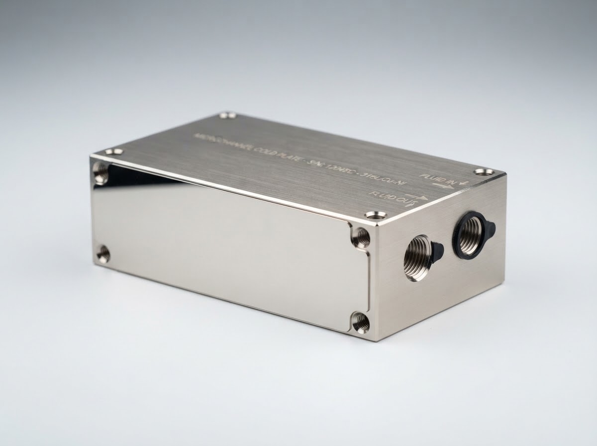
Copper microchannel cold plate with sealed nickel-plated body and dual precision side fluid ports

Microchannel Cold Plates

Compact internal channels bring coolant close to concentrated heat sources for demanding diode and driver footprints.

Best fit: compact, high heat-flux modules.

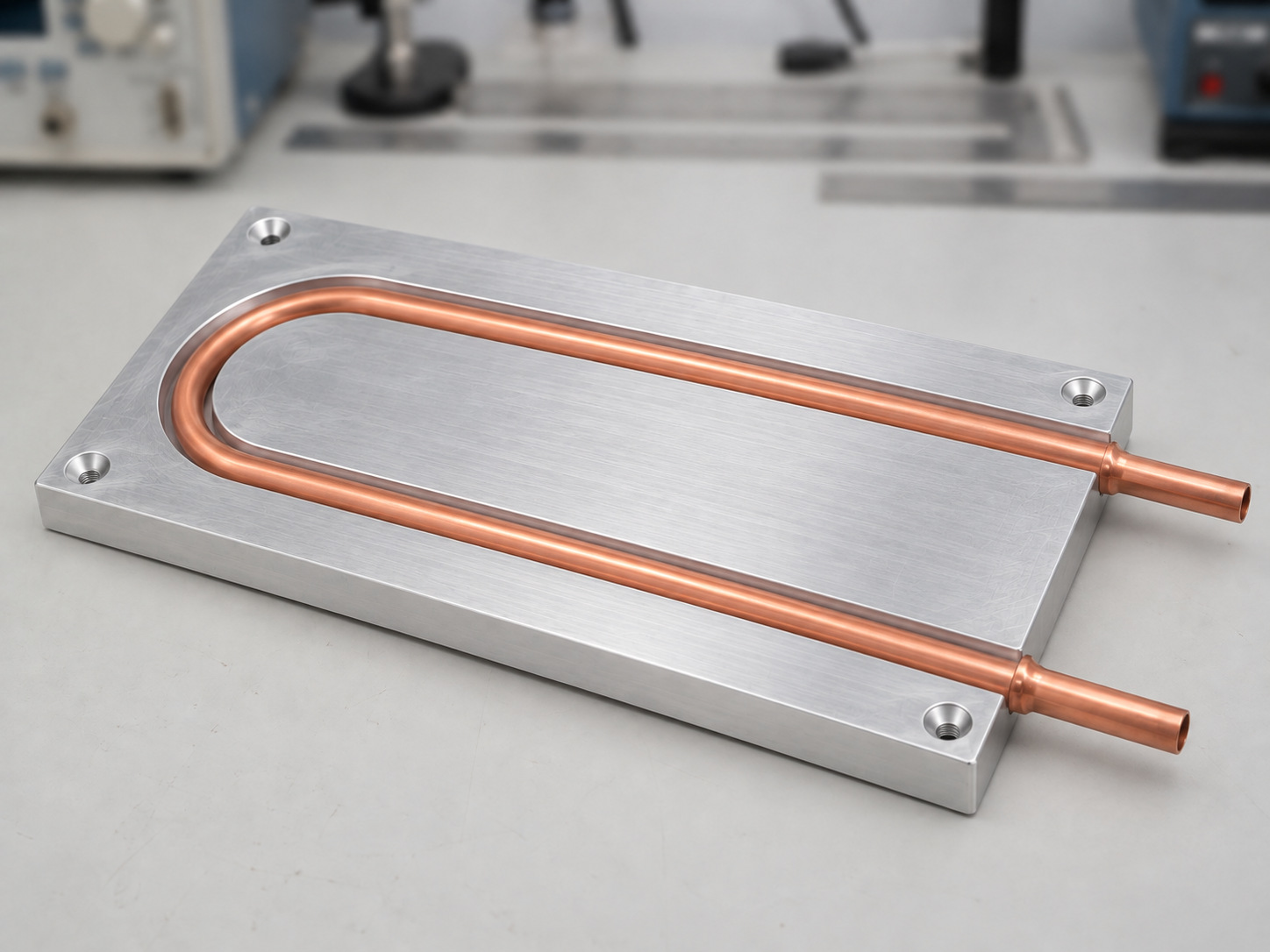
Aluminium tube-in-plate cold plate with a continuous embedded U-shaped copper tube and two open tube ends

Tube-in-Plate Cold Plates

A continuous embedded tube offers a practical coolant path for larger mounting areas and moderate heat density.
Best fit: distributed loads and straightforward loop integration.
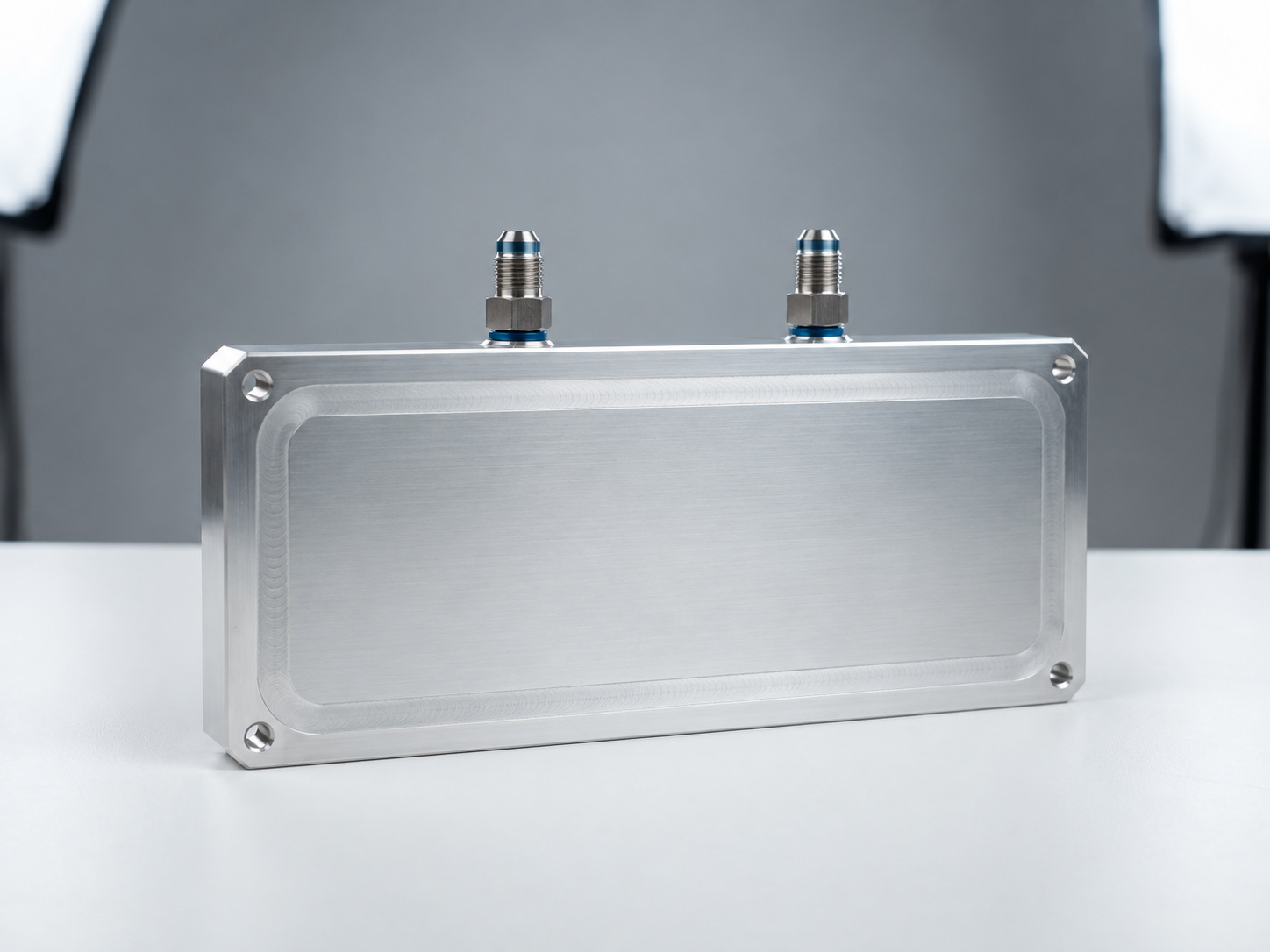
Aluminium friction stir welded liquid cold plate with clean flush perimeter weld seam and dual fluid connectors

Welded & Brazed Cold Plates

Custom enclosed flow paths support larger baseplates, multiple heat sources and application-specific connection locations.
Best fit: integrated liquid-cooled equipment platforms.
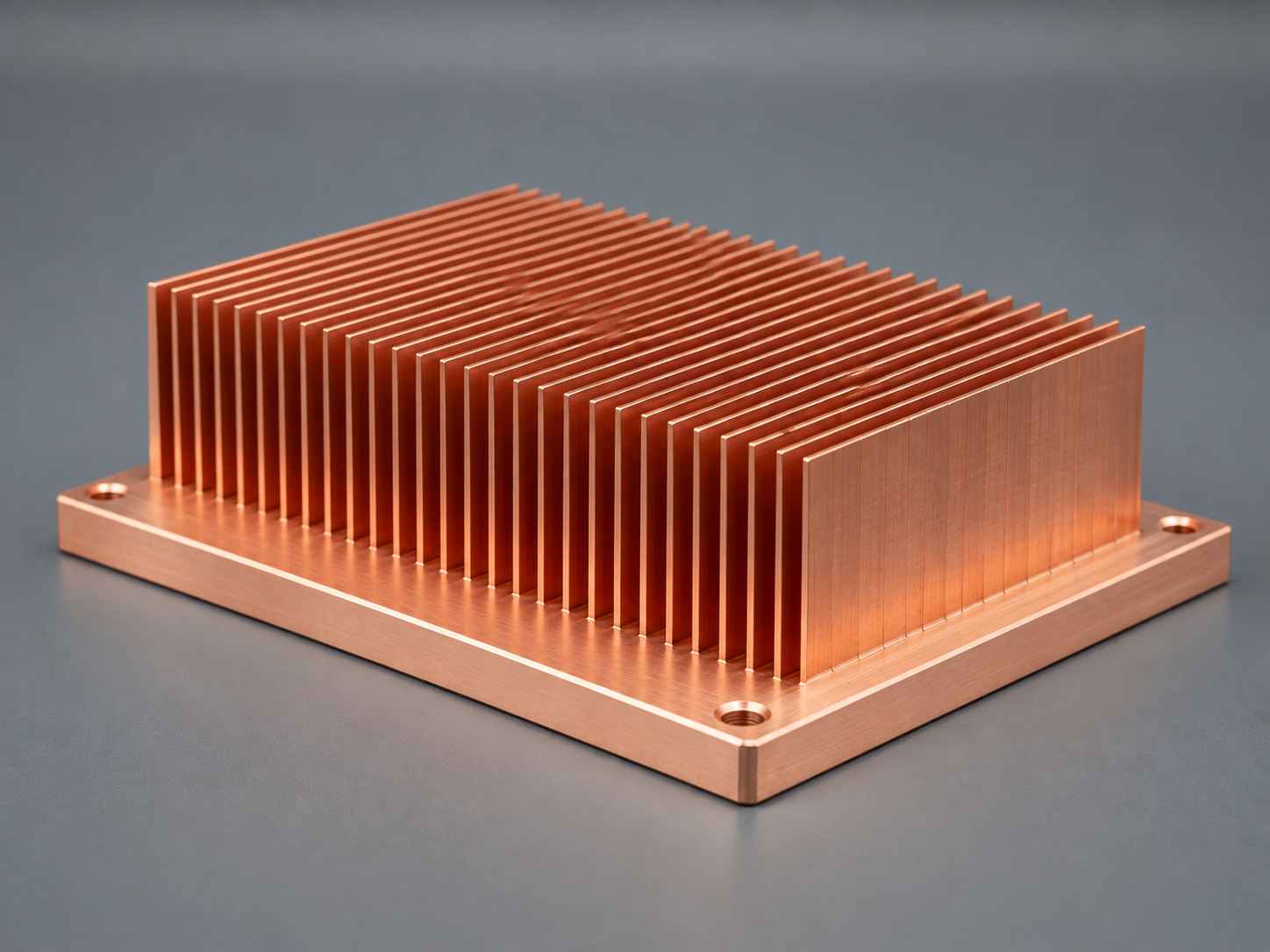
C1100 pure copper skived fin heat sink with uniform parallel integral cooling fins on thick machined base

Precision CNC & Skived Heat Sinks

Machined interfaces and integral fins support compact drivers and control electronics where a verified airflow path is available.

Best fit: air-cooled auxiliaries and precision mounting.

Compare the right process before committing to a thermal design.

Compare Cooling Options
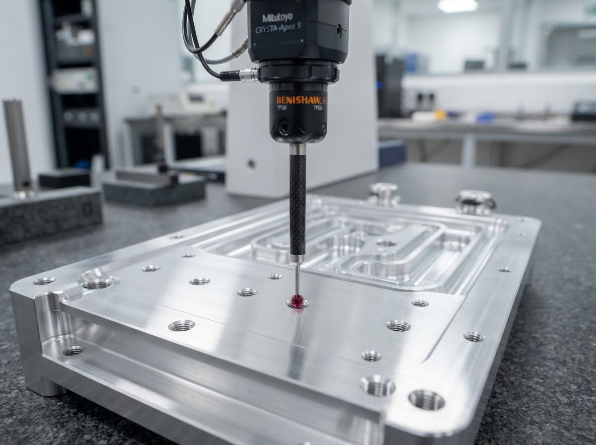
Coordinate measuring machine ruby probe inspecting the machined thermal mounting face of an aluminium liquid cold plate

Precision at the Interface Protects the Whole Assembly

Contact geometry, coating control and mounting load all affect heat transfer and alignment. We define these details on the approved drawing before production.

≤0.05 mm Typical contact-face flatness over 100 mm.
±0.02–0.05 mm Selected local critical dimensions after drawing review.
Ra 0.8–1.6 μm Precision thermal-interface surface finish.
Drawing-defined Masking, datums, clamping and final-state inspection.

Targets are reviewed together with part size, material, coating and fixture strategy.

Bring your critical datums, contact area and mounting loads into the review.

Request an Interface Review

A Reliable Loop Starts Beyond the Cold Plate

Thermal performance must work with coolant chemistry, filtration, pressure limits and the surrounding environment.

Flow Where It Is Needed

  • Balance the branches around the real heat-source layout.
  • Validate plate pressure drop against the pump working point.
  • Provide practical filling, venting and draining access.

Materials That Work Together

  • Review wetted metals, seals and the specified coolant.
  • Set filtration and cleanliness against the smallest passage.
  • Control residues and protect ports through delivery.

A Dry, Stable Environment

  • Keep exposed cold-plate and coolant-line surfaces above the local dew point with an operating margin.
  • Review insulation or enclosure control where required.
  • Specify external chiller temperature stability, flow and leak-monitoring interfaces with the equipment controls.
1 Coolant specification
2 Clean flow path
3 Verified connections
4 Stable operation

Resolve flow, chemistry and condensation before the first prototype.

Review Your Cooling Loop

Validate the Component Under Your Operating Conditions

A useful test report makes the conditions reproducible, so engineering and supplier quality can approve the same thermal component.
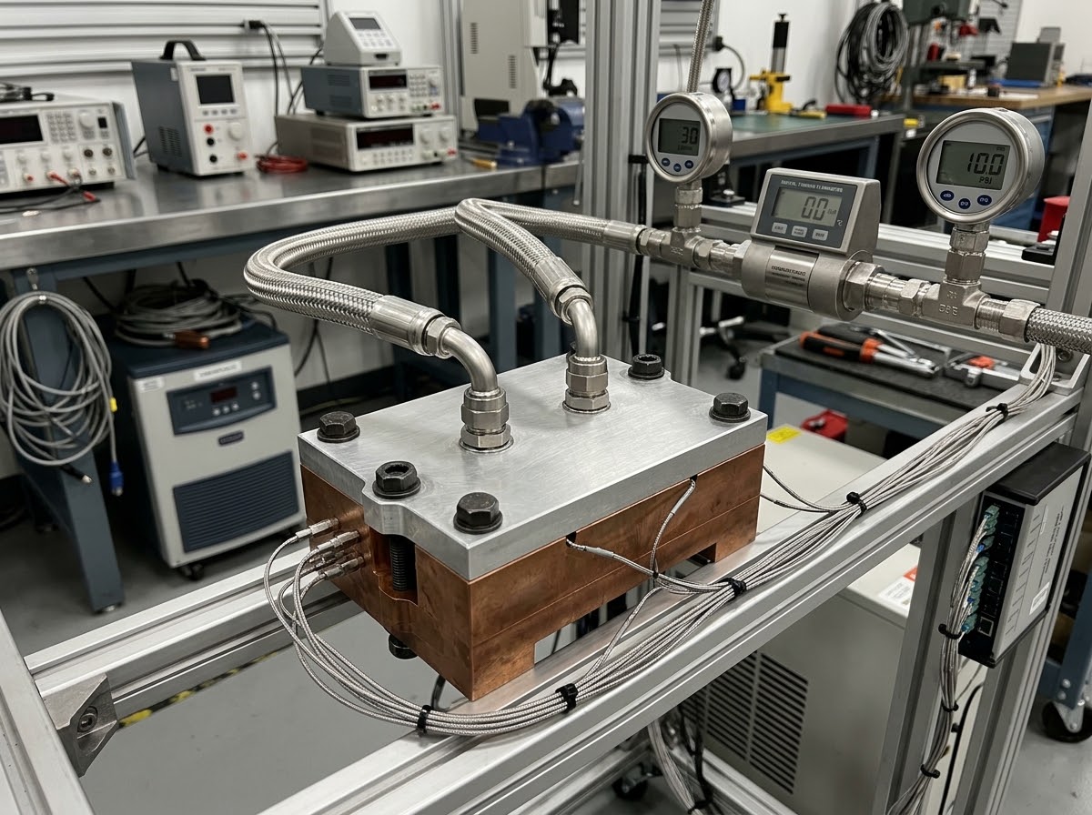
Thermal performance
Record source size, power, inlet conditions, installed airflow or coolant flow, sensors and steady-state criteria; assess warm-up, load changes and temperature gradients at agreed precision datums.
Flow & pressure drop
Measure plate inlet-to-outlet pressure loss at the specified coolant composition and flow.
Pressure & leak integrity
Define proof pressure and gas-leak limits for the approved design, with individual cold-plate test records.
Dimensions & traceability
Link critical dimensions, material batches and inspection results to the released drawing.
Liquid cold-plate thermal and flow test bench apparatus with precision pressure transducers, digital turbine flowmeter and clamped heater simulation block in an industrial quality engineering laboratory
Defined boundary conditions
Recorded test method
Traceable results

Turn the validation plan into a clear production acceptance standard.

Plan Your Verification

From Thermal Brief to a Repeatable Production Part

One coordinated review connects your engineering requirements with prototypes, approval records and controlled batch supply.

01 Phase 1

Define the Requirements

Share loss maps, target temperatures, mounting space, coolant or airflow conditions and annual demand.

Output: a reviewed thermal brief.
02 Phase 2

Develop & Review

Compare processes, resolve interfaces and agree the drawing, materials and test scope.

Output: DFM and an approved design direction.
03 Phase 3

Prototype & Verify

Build samples, check fit and evaluate thermal, flow and leak performance against the agreed conditions.

Output: samples and first-article / test records.
04 Phase 4

Freeze & Scale

Release the drawing and control plan, approve changes and protect critical features during batch delivery.

Output: traceable production components.

Start with a drawing or a thermal requirement. We will define the next step.

Start Your Engineering Review
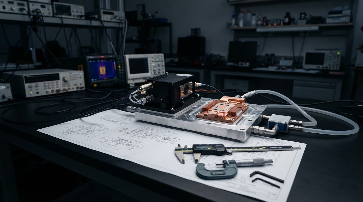
Precision thermal engineering laboratory workbench with laser assembly and cold plate components

Bring Your Laser Thermal Challenge into Focus

Share your heat load, mounting envelope and cooling conditions. Our team will help define a practical route from thermal requirement to production component.

  • Cold plates and precision heat sinks reviewed together.
  • Thermal, mechanical and fluid interfaces considered early.
  • Prototype and first-article documentation available.
  • Controlled drawings, material batches and engineering changes.
  • English technical coordination from sample to repeat supply.

Discuss Your Project

A few project details are enough to begin.

Your project information stays confidential. We reply within one working day.