
Microchannel Cold Plate for Energy Storage PCS
A compact aluminum cooling solution that handled a 1,000 W power-module load with a 49°C baseplate hotspot and 23 kPa plate pressure drop.
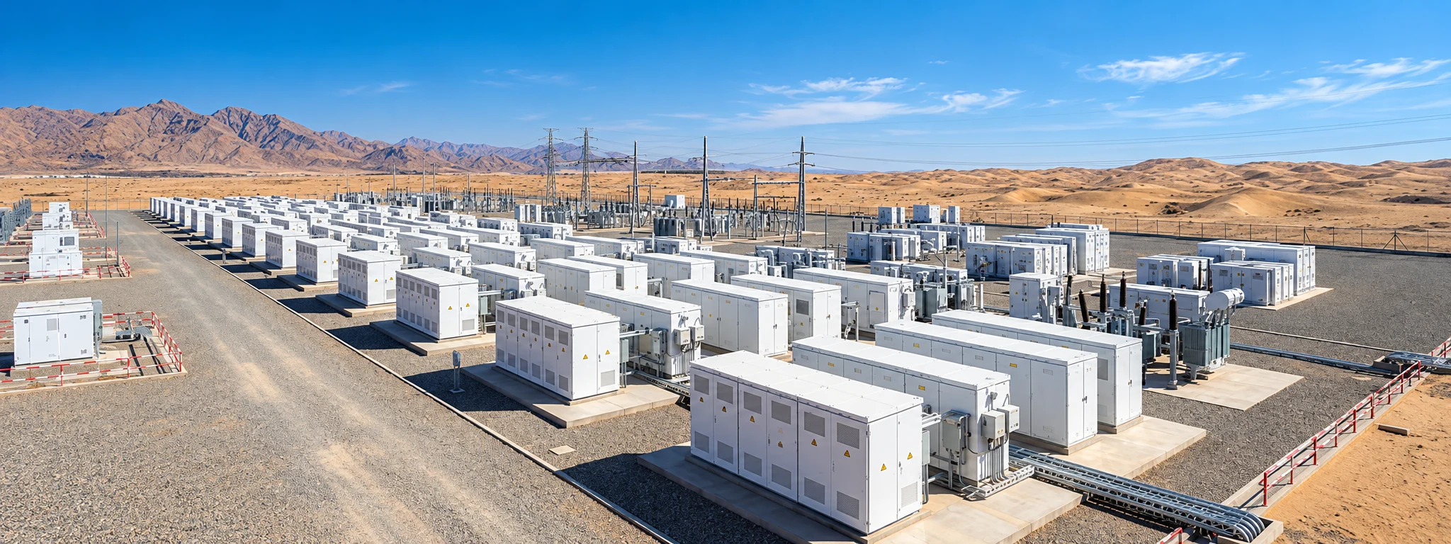
A Compact Cooling Challenge in a UAE PCS Platform
An energy storage integrator needed repeatable cooling for a concentrated power-module load without expanding the available mechanical envelope.
Clear Targets Before the Channel Design Began
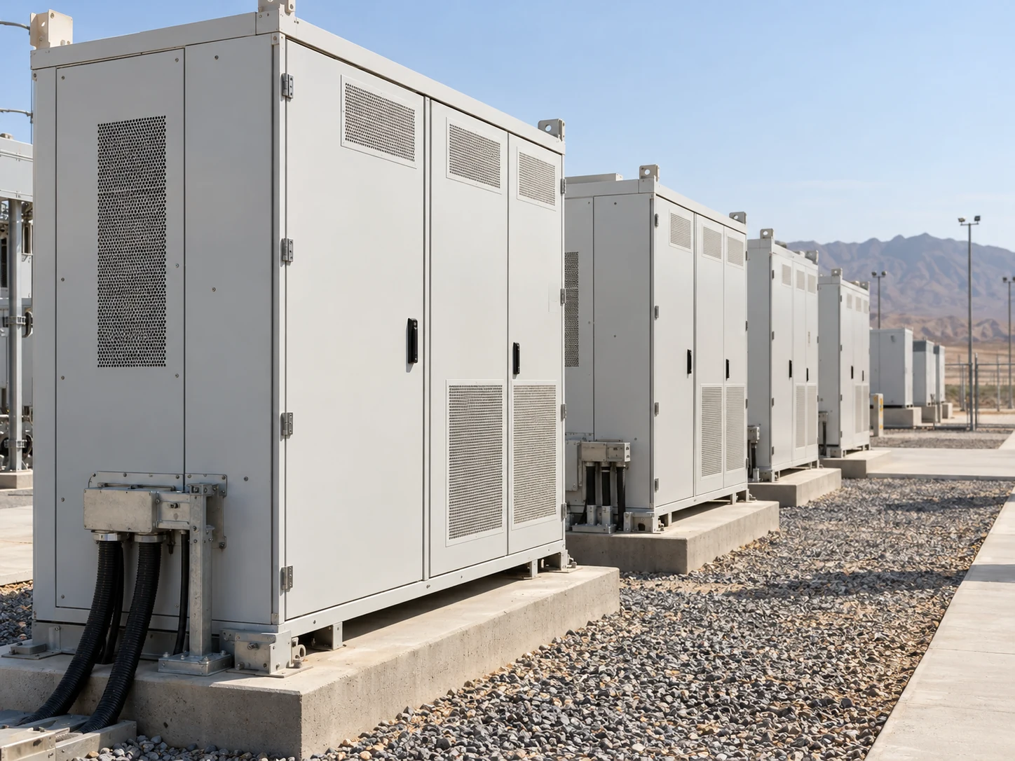
Thermal, hydraulic, mechanical, and coolant boundaries were defined together so the cold plate could be evaluated under repeatable conditions.
Applied over the specified 80 × 80 mm contact area.
Filtered water entering the plate at 25°C.
Measured between the cold-plate inlet and outlet.
Gauge pressure for the approved cold-plate design.
The Cold Plate Built Around the Power Module
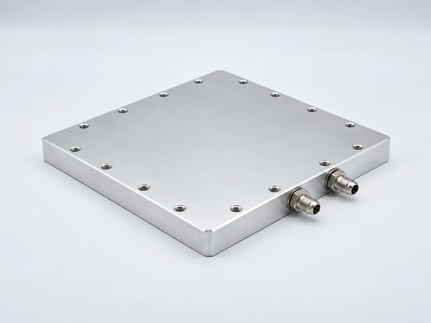
An aluminum microchannel core, balanced inlet distribution, and a controlled contact surface created a short, direct thermal path within the existing envelope.
Four Engineering Decisions That Made the Design Work
The design addressed flow distribution, contamination, coolant compatibility, and module contact as one connected engineering task.
Distribute the inlet flow
An inlet balancing region feeds the parallel passages so the active core receives a more uniform coolant supply.
Control channel cleanliness
Deburring, flushing, cleanliness checks, and an absolute-rated 50 μm filter specification help protect the small passages.
Define the coolant chemistry
Material-compatible inhibited coolant, controlled water quality, and a reviewed wetted-material stack address corrosion risk.
Stabilize the thermal interface
The contact surface, mounting features, TIM selection, and clamping method are reviewed together for repeatable heat transfer.
Resolve the fluid path and mounting interface before freezing the drawing.
Request an Engineering ReviewValidation That Can Be Repeated on Your Bench
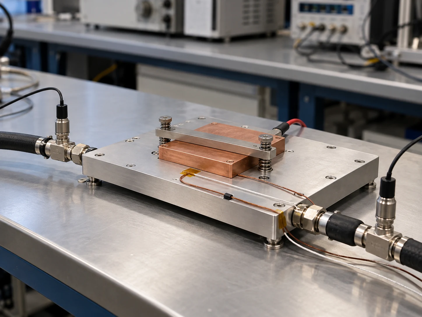
The component was measured at a defined heat load, inlet temperature, and flow rate, with plate-only pressure drop and coolant energy balance checked together.
Thermal measurement
1,000 W heat input; 80 × 80 mm source; 25°C inlet water; 10 L/min flow; baseplate hotspot recorded at steady state.
Hydraulic measurement
Pressure taps at the cold-plate inlet and outlet isolate the component pressure drop from external hoses, filters, and the pump.
Energy-balance check
The measured water temperature rise of approximately 1.4 K was consistent with the applied heat load.
Align the fixture, sensor locations, and flow conditions before comparison.
Discuss the Validation SetupMeasured Results with Room Inside the Hydraulic Limit
The cold plate met the component cooling target while remaining below the specified plate pressure-drop ceiling under the defined water test conditions.
At 1,000 W and 25°C inlet water.
Calculated from the measured 24 K rise.
7 kPa below the 30 kPa requirement.
Consistent with the heat-balance check.
Evaluate performance using the same boundary conditions as your system.
Check Your Operating PointFrom a Passing Component to a Traceable Delivery
Each cold plate passed the specified pressure and leak checks, while controlled drawings and inspection records supported the first 240-unit delivery.
10-minute hold for the 0.3 MPa rated design; no leakage or permanent deformation.
Dry air or nitrogen at 0.3 MPa after draining, cleaning, and drying; acceptance ≤0.05 sccm equivalent air leakage.
Component inspection and release records accompanied the production shipment.
Engineering handover
- Approved drawing and revision
- Material and surface specification
- Thermal and pressure-drop test conditions
Quality handover
- FAI and key-dimension report
- Serialized pressure and leak records
- Material lot and shipment traceability
Connect the approved sample to the records supplied with production.
Discuss Your Quality File RequirementsWhat Transfers to Your Next PCS Project
The case provides a starting point for compact power-module cooling, with coolant, hydraulic, and interface details reviewed against your own system boundary.
Can the water results be used for a glycol loop?
What protects the microchannels from blockage?
What should be checked at the mounting interface?
What information is needed to begin?
Start with the boundary conditions that determine your cooling result.
Send Your PCS Requirements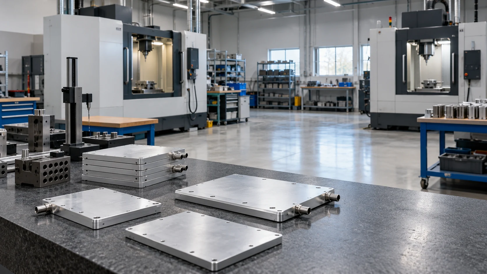
Build a Cold Plate Around Your PCS Requirements
Share your heat load, coolant conditions, and mechanical envelope. Morton engineers will review the fit and define the next step for a custom cooling component.