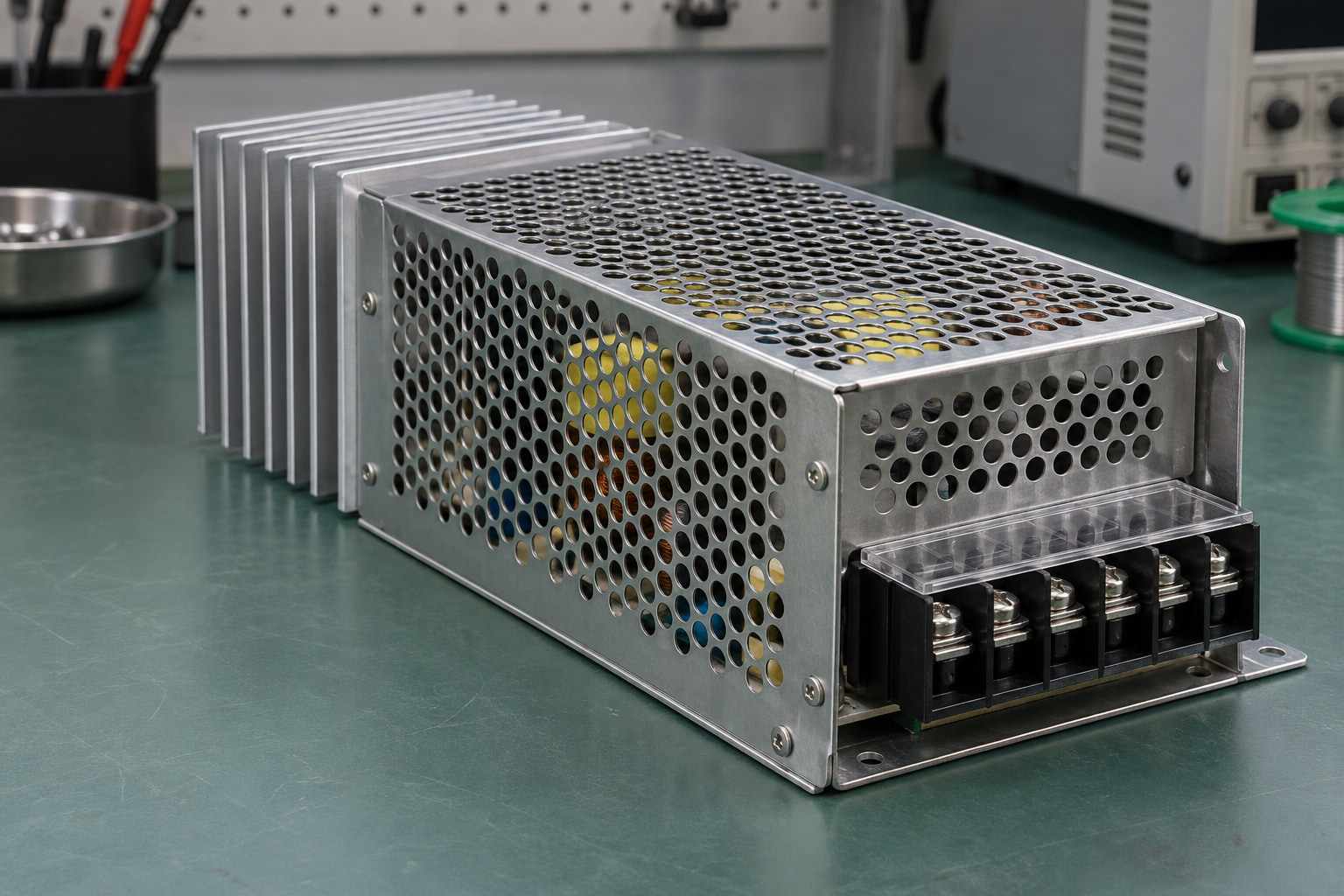
Industrial power supplies
Transfer heat from power devices into a machined base and straight-fin field sized for the available enclosure airflow.

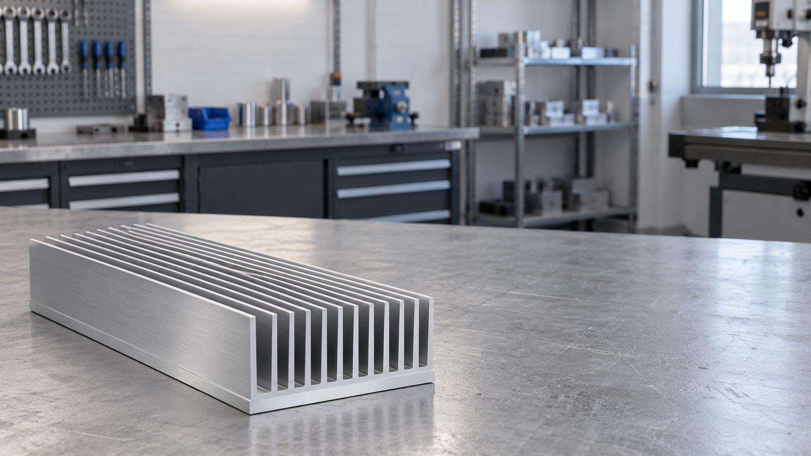
Custom aluminum profiles, precision machining and controlled finishing for industrial OEMs. Move from a reviewed drawing to a repeatable production part with morton.
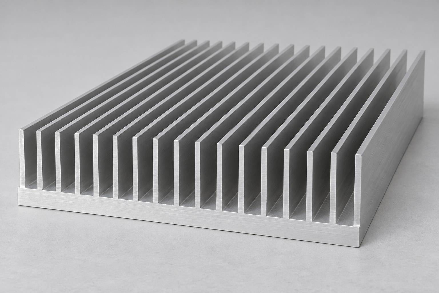
An extruded heat sink forms the base and fins from one aluminum profile. A consistent cross-section supports efficient repeat production, while machining adds the interfaces your assembly needs.
The continuous metal structure carries heat from the mounting face into the fin field without a bonded fin joint.
Cut the profile to the required length, then machine mounting holes, threads and contact surfaces.
Fin geometry, heat-source footprint and installed airflow are reviewed together to control temperature rise.
Keep the thermal path, mechanical fit and purchasing plan aligned with a profile that is practical to manufacture and easy to inspect.
Integral fins eliminate a separate fin-to-base bonding operation, reducing process variables in the heat-spreading structure.
Controlled contact faces, hole positions and threads help the approved part fit the first time.
Material batches, drawing revisions and packaging identifiers stay linked from sample approval to replenishment.
Existing-profile review, machining access and quantity-based pricing expose practical ways to reduce total part cost.
Find the strongest combination of cooling, fit and unit cost.
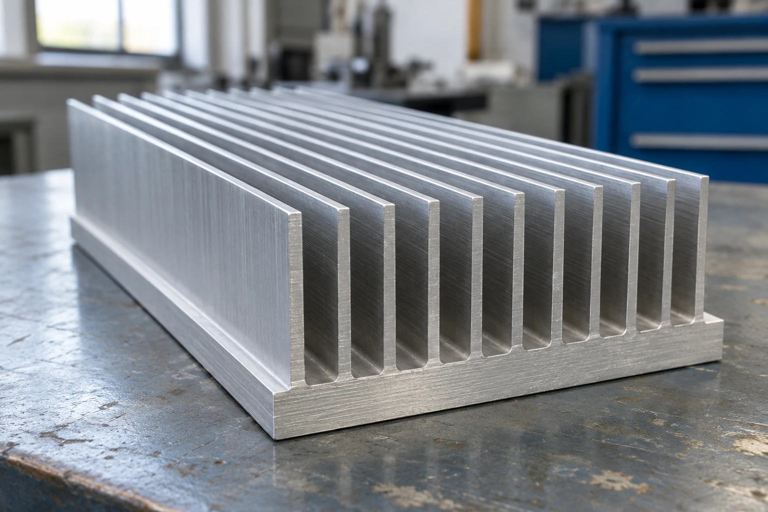
Explore My OptionsUse these routine extrusion ranges to start the discussion. Profile geometry, structural stability and machining access are reviewed together before the drawing is frozen.
| Profile Dimension | Standard Manufacturing Range |
|---|---|
| Cross-section width | 20–300 mm |
| Overall height | 10–100 mm |
| Cut length | 30–800 mm |
| Base thickness | 3–20 mm |
| Fin thickness | 1–3 mm |
| Clear fin spacing | 2–12 mm |
Send the complete geometry so fin height, thickness, spacing and base strength can be assessed as one profile.
Check the feasibility of your cross-section before committing to tooling.
Check My ProfileThermal conductivity matters alongside strength, machining requirements and surface finish. We review the alloy and temper against your approved specification.
A practical choice for extruded fin profiles and anodized appearance. Reference room-temperature conductivity: approximately 200 W/(m·K), depending on temper and temperature.
Selected where the mechanical specification and machining requirements favor 6061. Reference room-temperature conductivity: approximately 167 W/(m·K), depending on material condition and temperature.
Balance conductivity, strength and manufacturing requirements.
Confirm My MaterialA denser fin field is useful only when the installation can move air through it. We evaluate spacing, orientation and bypass paths against the actual enclosure.
Allow an open inlet and outlet, use an installation orientation that supports buoyancy, and preserve practical clear spacing between fins.
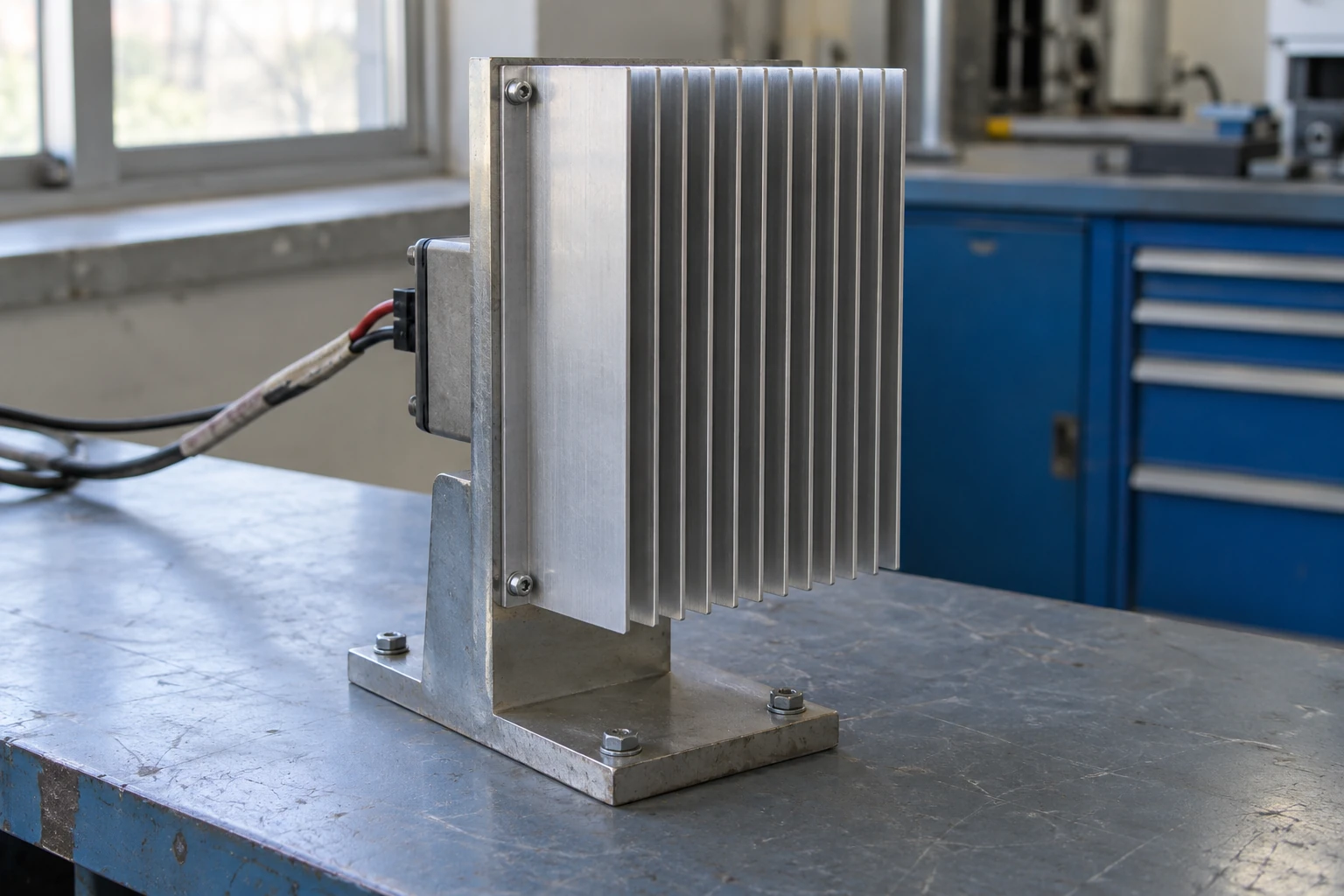
Use measured airflow through the heat sink, check the fan operating point and pressure drop, and limit bypass around the fin field.
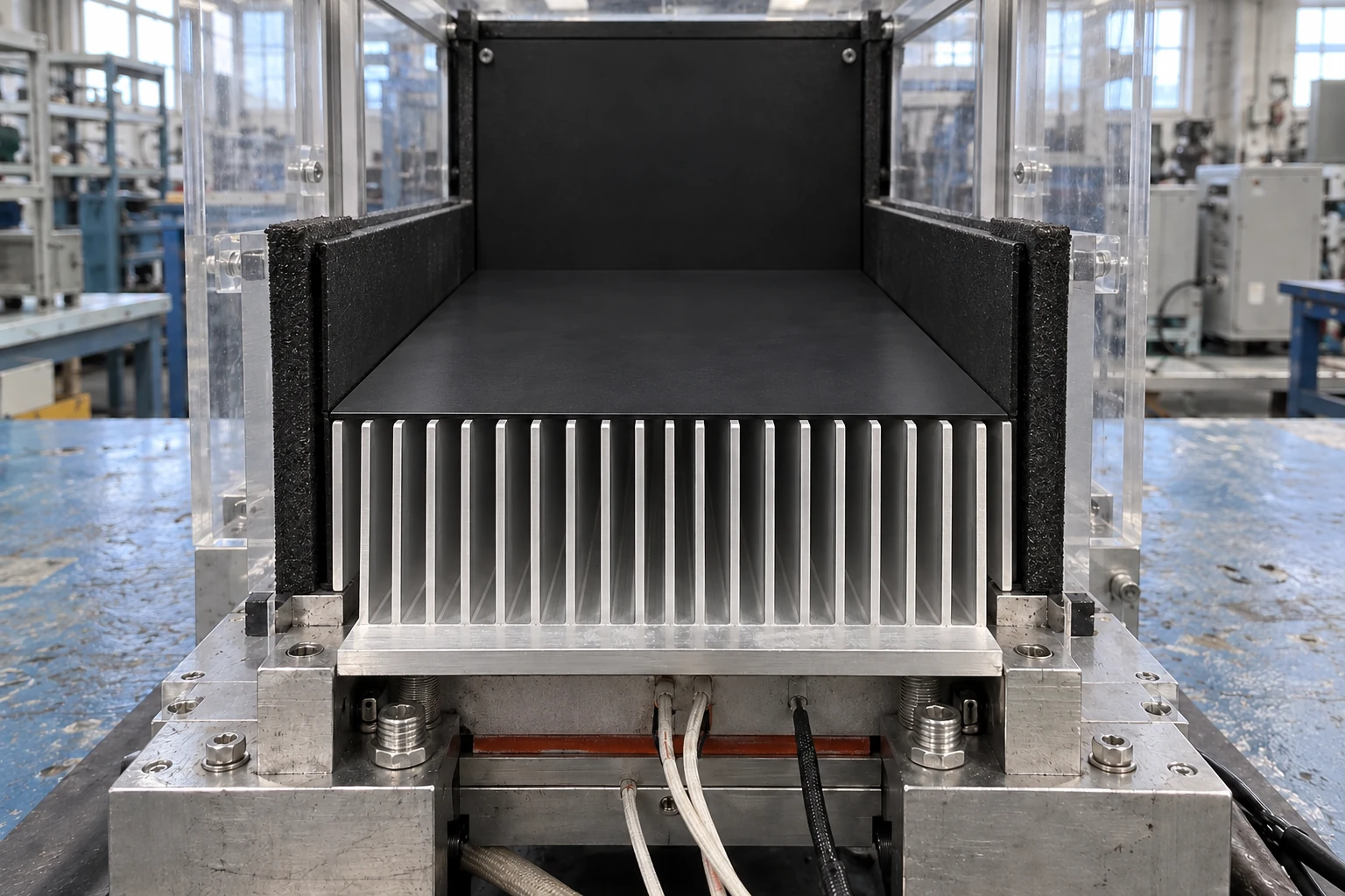
Design for the airflow inside your equipment.
Review My AirflowAn extrusion becomes an assembly-ready component through controlled machining of the contact face, hole pattern and mounting details.
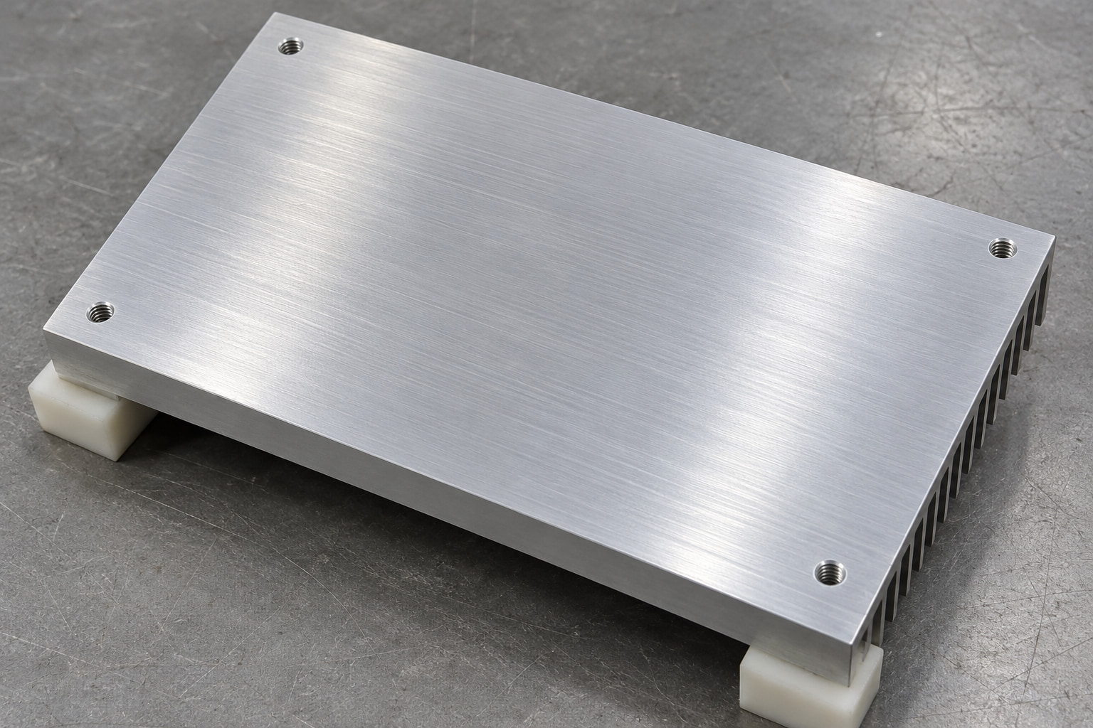
Surface treatment is defined around corrosion exposure, appearance, electrical contact and the thermal interface so the finished part remains assembly-ready.
Natural, black or specified-color anodizing creates a controlled visual finish. Standard anodic film is typically 10–20 μm.
Define thermal contact faces, grounding points and threads that must remain bare or receive a specified alternative treatment.
Inspect dimensions and coating requirements after processing so the fit reflects the part that enters your assembly.
Extruded profiles suit repeatable air-cooled assemblies where the heat load, installation space and manufacturing economics can be defined together.
Transfer heat from power devices into a machined base and straight-fin field sized for the available enclosure airflow.
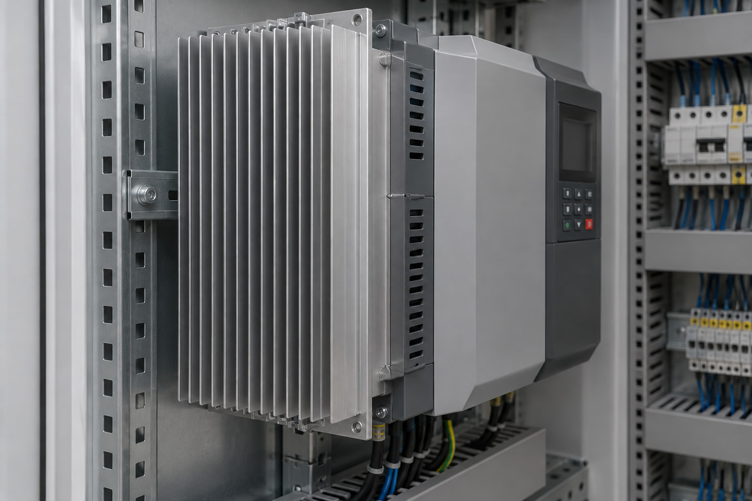
Align the contact plane, mounting pattern and air path with the power stage to reduce assembly uncertainty.
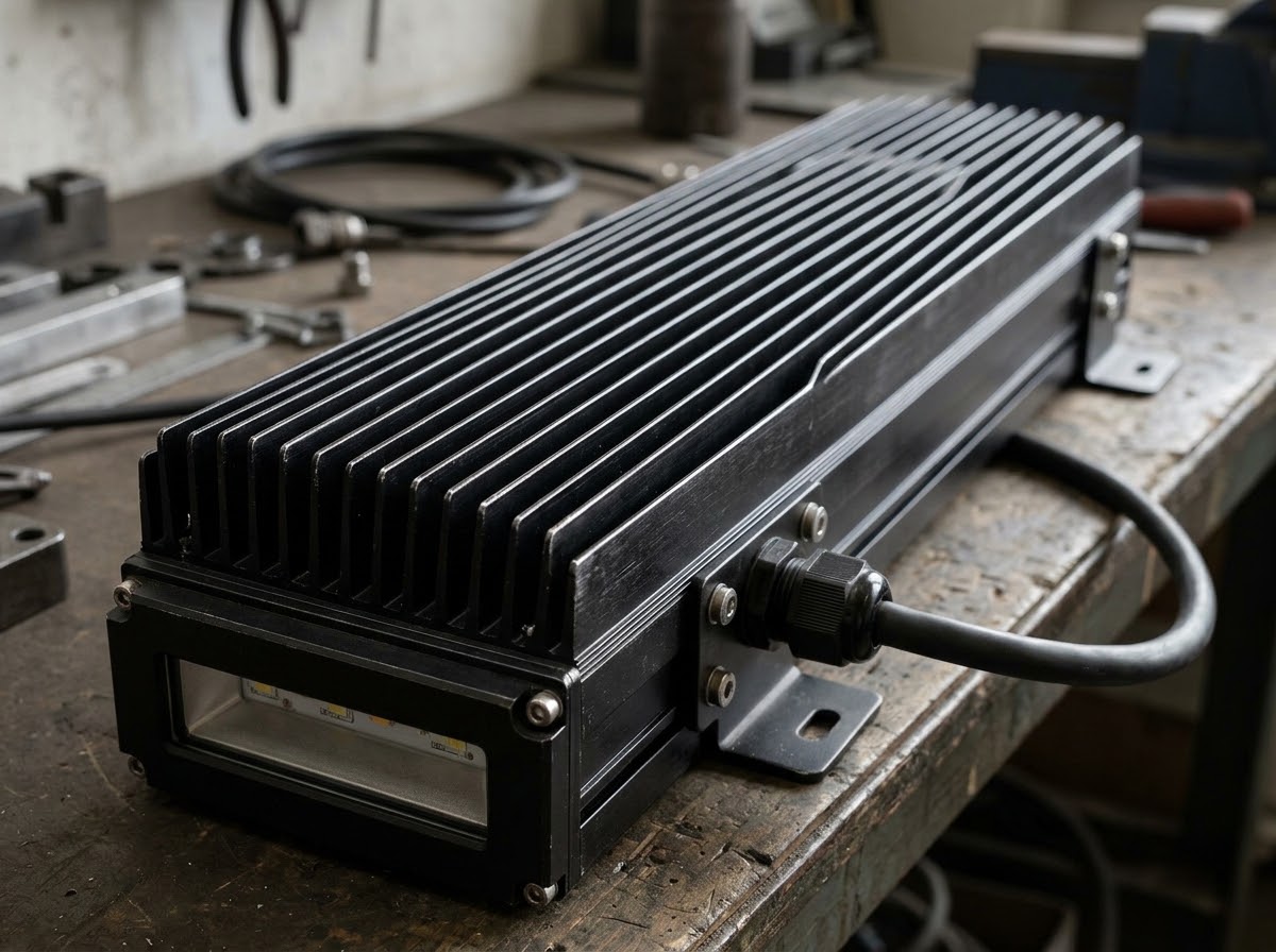
Combine a repeatable aluminum profile with the required mounting face and orientation for controlled heat removal.
A useful thermal number identifies the heat source, inlet temperature and measured airflow. That makes the result relevant to your design review.
| Heat sink envelope | 200 × 150 × 50 mm |
|---|---|
| Heat-source footprint | 50 × 50 mm |
| Effective thermal load | 200 W |
| Inlet air temperature | 25 °C |
| Measured installed airflow | 80 m³/h |
| Base hotspot-to-inlet resistance | Approximately 0.25 K/W |
200 W × 0.25 K/W = 50 K base hotspot rise; approximately 75 °C at a 25 °C air inlet.
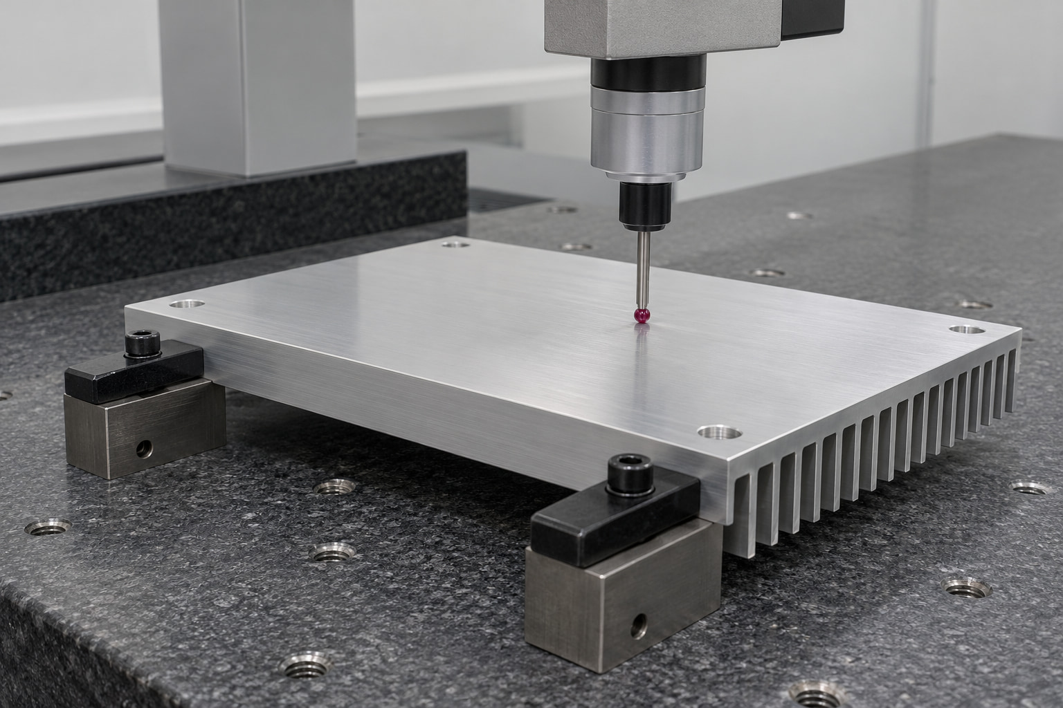
Incoming checks, first-article inspection and controlled release connect the approved drawing to each repeat production batch.
Build your inspection requirements into the manufacturing plan.
Plan My Quality DocumentsEngineering, quality and purchasing move through the same controlled milestones so the sample you approve defines the production part.
Share 2D/3D files, heat load, air boundary and forecast volume. Review profile feasibility, interfaces and the quote scope.
Confirm the drawing, material and finish. Routine drawing-led samples typically take 10–20 working days after the drawing is frozen.
Check first-article dimensions and test the assembly under the agreed operating conditions before production release.
Schedule repeat orders against the approved revision and packaging plan. Mature parts with existing tooling typically run in 15–30 calendar days once release conditions are met.
Give your project a practical path to production approval.
Start My Project ReviewFor a U.S. industrial thermal brand, the task was to make mounting fit, anodized appearance and part identification repeatable across an extruded heat sink program.
Introduce three interchangeable anodized extruded parts with stable hole patterns, color, packaging and English part identification.
6063-T5 profiles, common datum fixtures and machined contact surfaces; critical hole locations controlled to ±0.05 mm with individual dividers and linked batch labels.
Prepare the technical and purchasing details that help us return a useful feasibility review and a clearly scoped quotation.
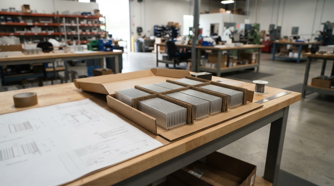
Tell us about the heat load, installation and production plan. We will help turn the requirements into a drawing-led manufacturing route.
Assess the profile, interfaces and machining scope.
Review heat-source size, inlet air and installed airflow.
Align the drawing, first article and inspection plan.
Keep revisions, labels and delivery requirements linked.