Precision fin heat sinks
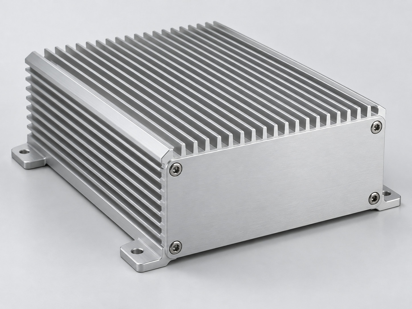
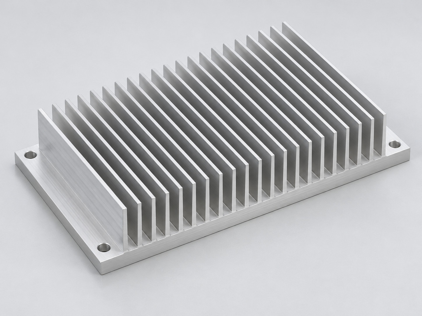
Extruded or skived fins balance spreading, pressure drop and available height. Machined contact faces and mounting details make the design repeatable at assembly.
Custom heat sinks, heat pipe assemblies and liquid cold plates for telecom and networking equipment—engineered around your hotspots, airflow and operating environment.
Bring your next network platform into thermal focus.
Discuss Your Thermal DesignHigher power density, restricted airflow and warmer installations can erode the thermal margin your network platform depends on.
Switch ASICs, processors and power stages concentrate heat in small footprints. Uneven spreading can trigger throttling before the enclosure reaches its temperature limit.
Dense boards, optics and cable routing add resistance. A fan's free-air rating cannot describe the air that actually reaches the fins.
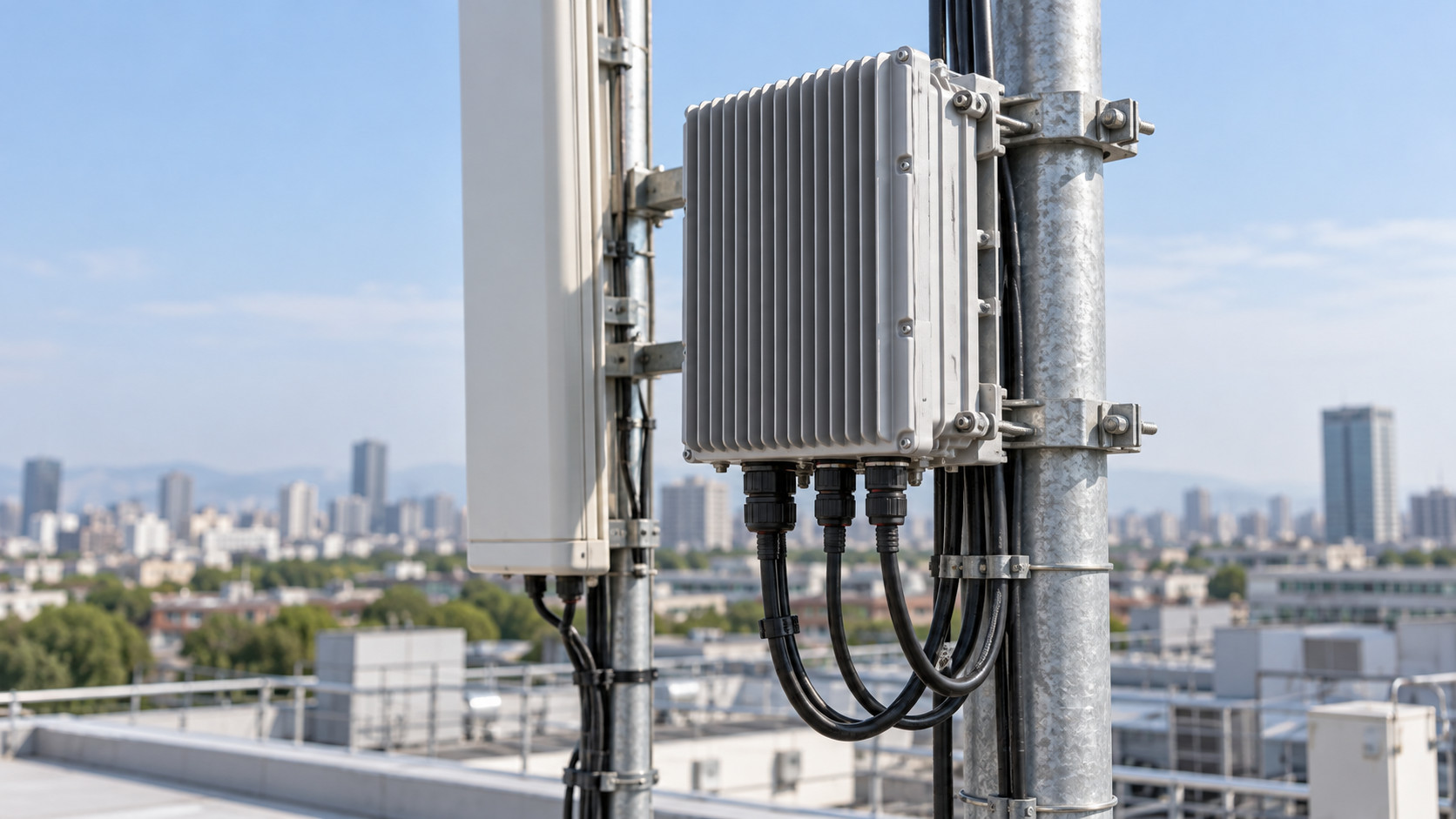
Sealed radio units and gateways must reject heat through their structure. Ambient temperature, solar exposure and mounting direction all change the result.
Changes in contact flatness, TIM compression or assembly force can shift temperatures between units and create rework during production ramp-up.
Tell us which constraint is limiting your platform.
Review Your Cooling ChallengeA reliable thermal solution begins with the conditions inside your equipment, not a standalone wattage claim.
Compare cooling routes against the same heat sources.
Check the installed fan or pump operating point.
Define acceptance conditions before sample approval.
Continuous and peak losses, hotspot footprint and component temperature limits.
Chassis flow path, measured flow through the fins, fan curve and acoustic target.
Inlet temperature, altitude, dust, solar exposure and installation orientation.
Height, board keep-outs, optics access, mounting loads and service clearance.
Coolant chemistry, inlet temperature, flow, pressure-drop budget and dew point.
Drawing revision, annual volume, inspection criteria and assembly process.
Select a cooling architecture that fits the heat source, enclosure and service conditions—then refine it for manufacturing.
Extruded or skived fins balance spreading, pressure drop and available height. Machined contact faces and mounting details make the design repeatable at assembly.
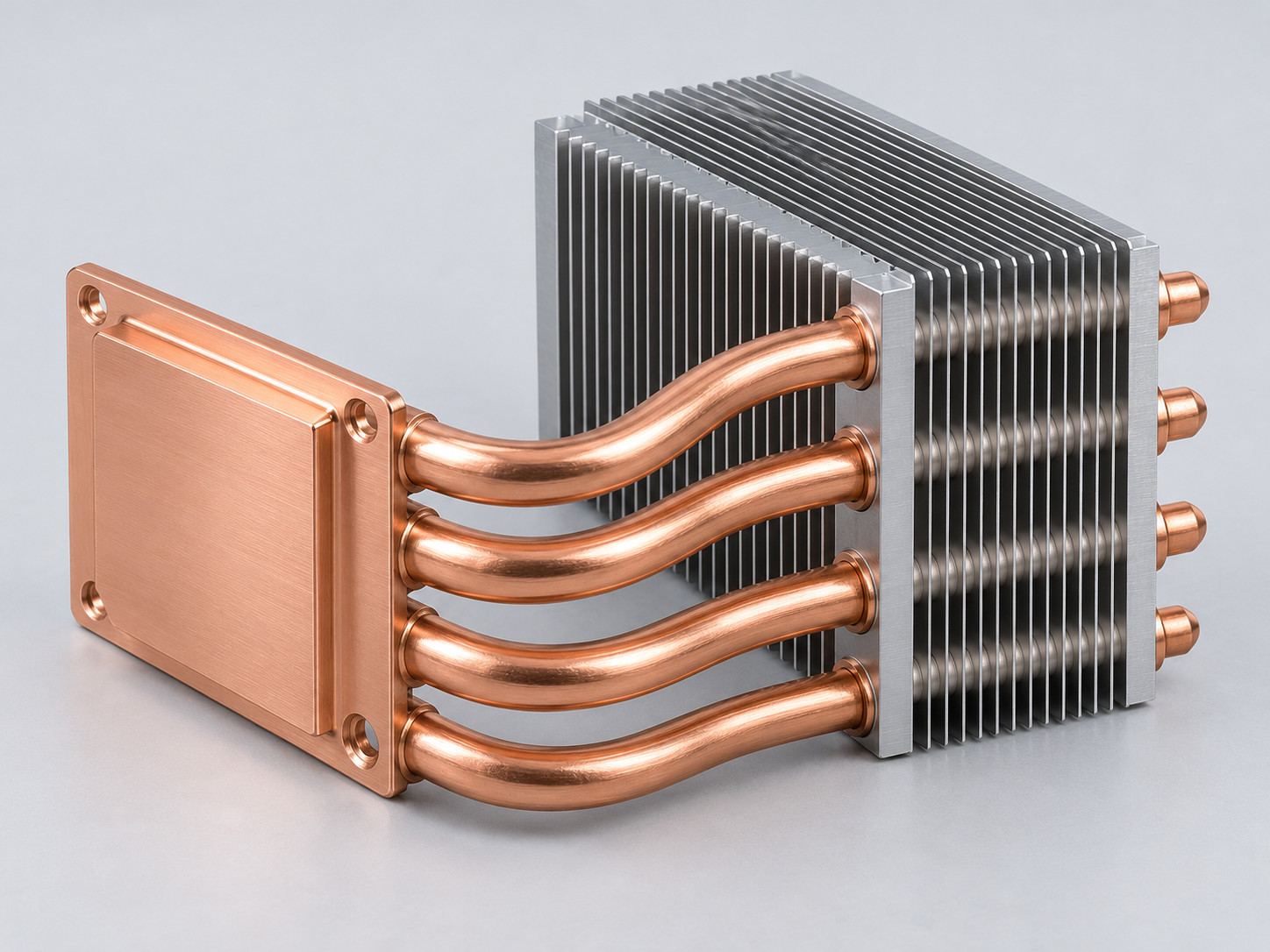
Move heat away from an offset hotspot or spread it across a larger fin area. Tube routing, contact blocks and orientation are validated together.
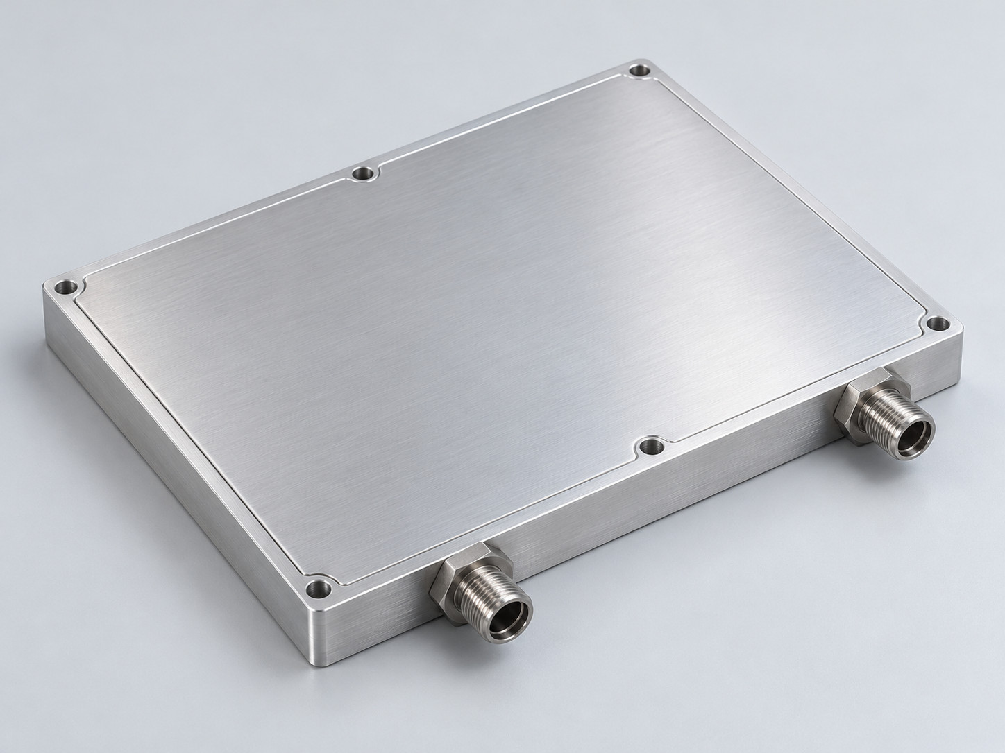
Bring high-density heat into a controlled liquid path. Channel layout, interfaces, cleanliness and pressure drop are developed around the equipment loop.
Turn the enclosure into a heat-rejection surface, with contact pads and mounting hardware selected as part of the thermal path.
Compare the options around your equipment, not a generic product list.
Find Your Cooling ArchitectureFrom rack-mounted switches to sealed field devices, each application demands a different balance of heat removal, access and reliability.
Spread ASIC and processor hotspots within low-profile airflow paths while preserving optical-module and connector clearance.
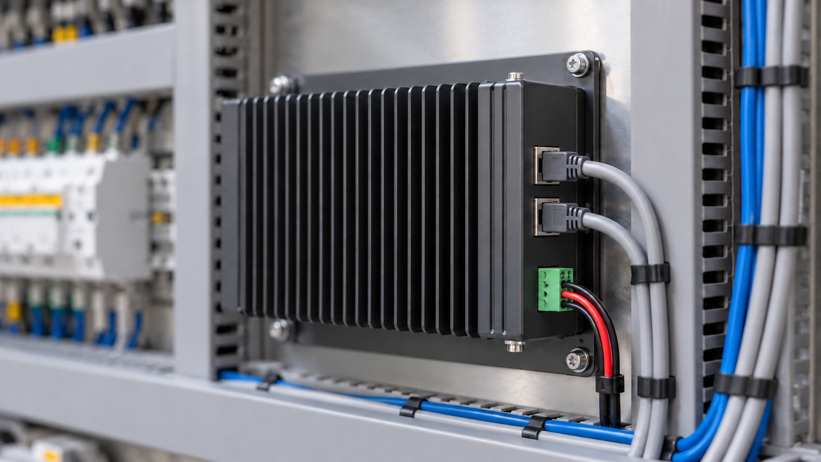
Conduct heat into a finned structure while coordinating seals, grounding surfaces and the installation direction.
Move losses from offset power devices into usable fin area without assuming that the existing fan can overcome added resistance.
Connect processors and power stages to the enclosure, with controlled pad compression and serviceable mechanical interfaces.
Thermal spreading, interface pressure and fluid resistance work together. We develop the complete path so the component can perform inside your equipment.
Define flatness, roughness, TIM thickness and mounting force together to limit contact resistance without overloading the package or PCB.
Choose base thickness, heat pipe routing or vapor chamber support around the hotspot footprint, component keep-outs and installation orientation.
Balance fin spacing or channel geometry against the installed fan or pump curve, and retain access for service and assembly.
A Singapore telecom power project used a heat pipe assembly to connect a concentrated source to a larger fin area within the existing chassis envelope.
Let us define equally clear acceptance conditions for your project.
Discuss a Comparable DesignTurn thermal targets into documented checks, with the drawing, test conditions and inspection records tied to the same approved design.
Record the heat source, inlet conditions, orientation, sensor locations and measured airflow or coolant flow. Report pressure drop with liquid-cooling results.
Check critical contact faces, hole positions, component clearances and assembly loads against the approved drawing and first-article plan.
Apply the approved proof-pressure and leak-test procedure to each cold plate, with cleanliness, drying and coolant compatibility defined by the project.
Link material batches, drawing revisions, work orders and release records. Review changes to critical materials and processes before implementation.
Agree on what your teams need to approve the cooling component.
Plan Your Validation PackageKeep engineering, purchasing and manufacturing aligned through one controlled design and a defined approval path.
Review losses, hotspot maps, envelope, airflow or liquid conditions and expected volume.
Compare cooling routes, complete DFM and freeze the prototype drawing and interfaces.
Build samples and verify temperature, flow resistance, fit and project reliability criteria.
Approve a pilot build, inspection plan, packaging and rolling delivery schedule.
Standard drawing-based samples: typically 10–20 working days after drawing freeze.
Heat pipe, vapor chamber or liquid-cooling development: typically 4–8 weeks for the first sample-and-test round.
Share your application and the thermal or mechanical constraint you are working around. Our team will help define a practical next step.