
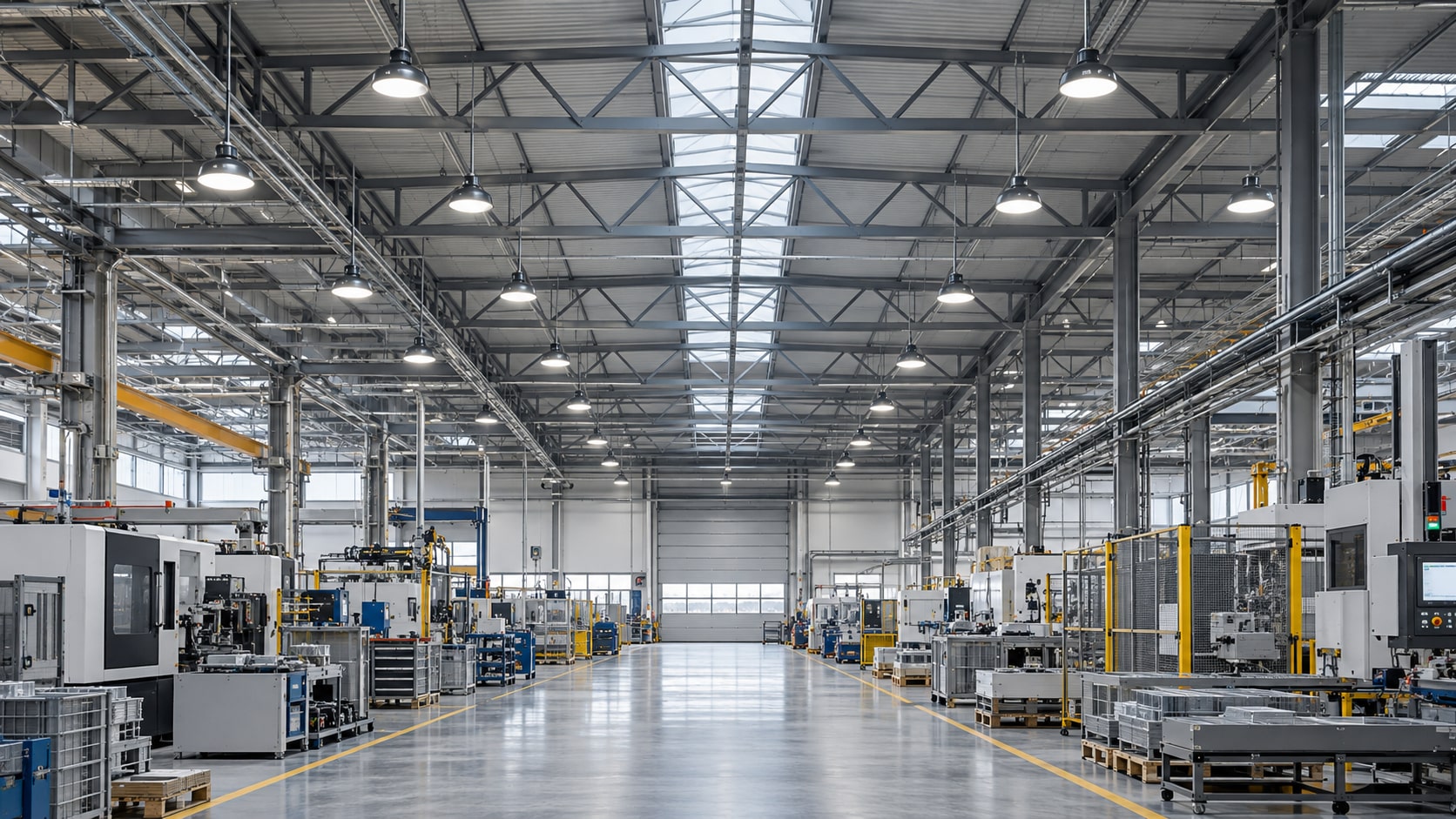
Thermal Management for LED & Industrial Lighting
Custom heat sinks, thermal housings and cold plates engineered around your light source, installation and production requirements.
When Heat Becomes a Lighting Problem
High ambient temperatures, compact optics and sealed housings can turn a promising lighting design into a difficult thermal compromise.
Elevated operating temperature
Higher LED junction and driver temperatures can reduce light output and shorten component life, increasing maintenance demands in hard-to-reach fixtures.
Concentrated heat at the source
COB arrays and compact LED boards need an effective spreading path before the heat reaches the fins.
Restricted heat rejection
Dust, installation orientation and sealed fixtures can limit airflow and the available external cooling surface.
Inconsistent thermal contact
Flatness, coating on mating faces and uneven clamping can make production performance drift from an approved sample.
A Better Thermal Path Protects the Whole Fixture
Control the complete path from the LED package to the surrounding air so thermal decisions support optical performance and serviceability.
Preserve optical consistency
Reduce avoidable temperature rise that can affect flux and color behavior.
Keep component limits in view
Review the LED and driver temperature limits together with the local ambient and enclosure layout.
Reduce redesign loops
Resolve thermal contact, mounting and cooling space before tooling and prototype approval.
Cooling That Fits the Lighting Application
Different fixtures reject heat in different ways. Match the cooling structure to the installation, heat density and environment.
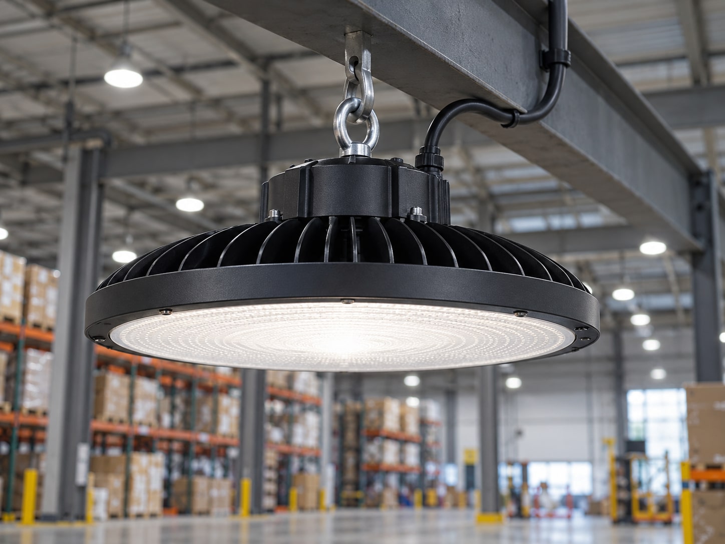
High-bay & warehouse lighting
Passive pin-fin or radial designs can support overhead installations where dust exposure and access for maintenance shape the cooling choice.
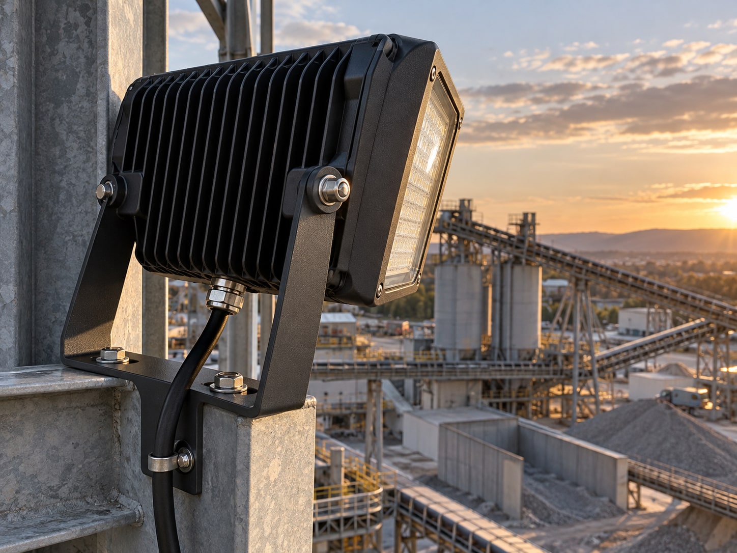
Outdoor & industrial floodlights
Finned housings and machined contact surfaces bring thermal spreading, structural mounting and environmental interfaces into one design review.
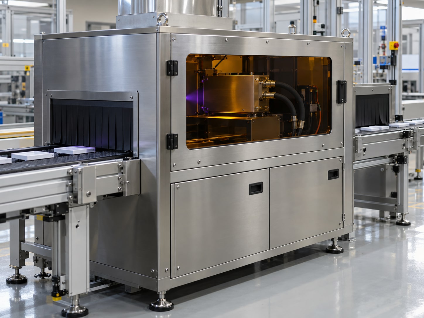
UV curing & high-flux LED equipment
Dedicated cold plates can remove concentrated waste heat where an approved liquid loop is available and passive cooling cannot meet the thermal budget.
Four Cooling Routes. One Application-Fit Solution
Select a manufacturing route that balances thermal resistance, fixture geometry, assembly effort and repeat-order cost.
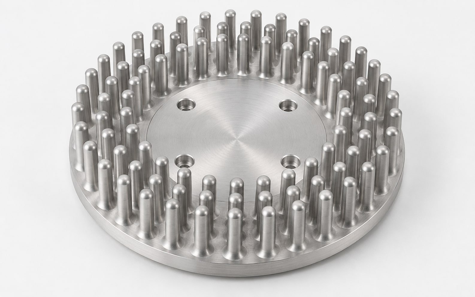
Cold forged heat sinks
Integral pin-fin or radial structures provide surface area for compact COB and high-bay designs, with spacing and mounting reviewed for the intended orientation.
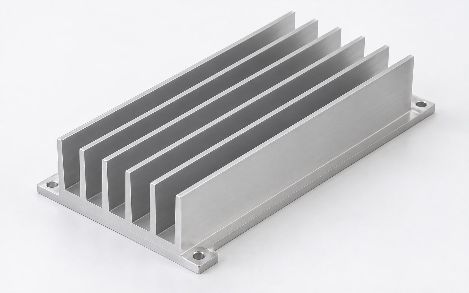
Extruded & CNC finished heat sinks
Consistent aluminum profiles with machined contact faces and mounting holes suit linear LED modules and repeatable fixture assembly.
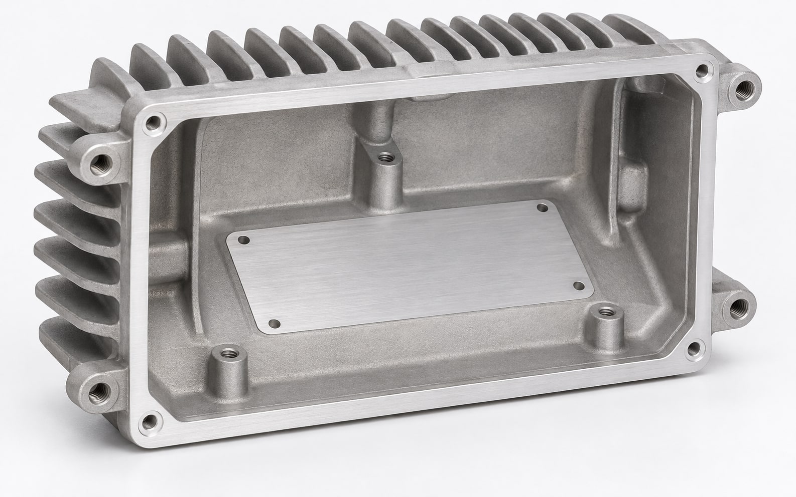
Die cast thermal housings
Integrated fins, bosses and mounting features reduce part count; critical thermal and sealing faces receive the required secondary machining.
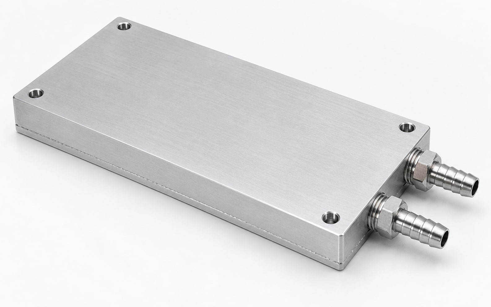
Liquid cold plates
Tube-in-plate, brazed or welded structures support high-flux UV LED assemblies with defined coolant, flow, pressure and connection requirements.
Engineer the Interface, Not Just the Fins
A capable heat sink still depends on the contact face, mounting system and fixture boundaries around it.
Contact surface & TIM
Specify flatness, roughness, interface material thickness and compression around the actual LED board or COB mounting area.
Mounting & optical clearance
Coordinate hole patterns, spring loading, tightening sequence and space for reflectors, lenses and wiring.
Finish & environmental interfaces
Mask thermal contact and grounding faces where required; review corrosion protection and sealing surfaces in the final assembly.
Airflow or liquid-loop boundaries
Define fin orientation and installed airflow, or the coolant, inlet temperature, flow, pressure drop and port standard.
Specify Heat Load Before Sizing the Heat Sink
Use LED waste heat and the worst operating condition to set a meaningful thermal target.
Validate the Assembly Under Real Conditions
Make the sample test repeatable, then carry the approved conditions into manufacturing and inspection.
Reproduce the thermal boundary
Record heat source layout, effective waste heat, inlet air or liquid temperature, orientation and installed airflow or flow rate.
Measure the right locations
Use defined contact points and calibrated sensors; account for surface emissivity when infrared imaging supports the assessment.
Check assembly durability
Verify contact quality, mounting force and thermal cycling against the agreed fixture and interface requirements.
Control liquid cooling risks
For cold plates, review material compatibility, pressure drop, cleanliness and the agreed leak and proof-pressure tests.
From Lighting Concept to Repeatable Production
Keep engineering, purchasing and quality aligned through one controlled development path.
Define the requirement
Review the light source, thermal load, fixture envelope, environment and volume together.
Select & refine the route
Compare cooling structures, complete DFM and coordinate interfaces before sample manufacture.
Build & validate samples
Check the assembly against the agreed thermal and mechanical test conditions.
Release & control supply
Freeze the BOM, inspection plan, packaging and change-approval process for repeat orders.
Start with the inputs you have. We will identify the next engineering step.
Start My Development Review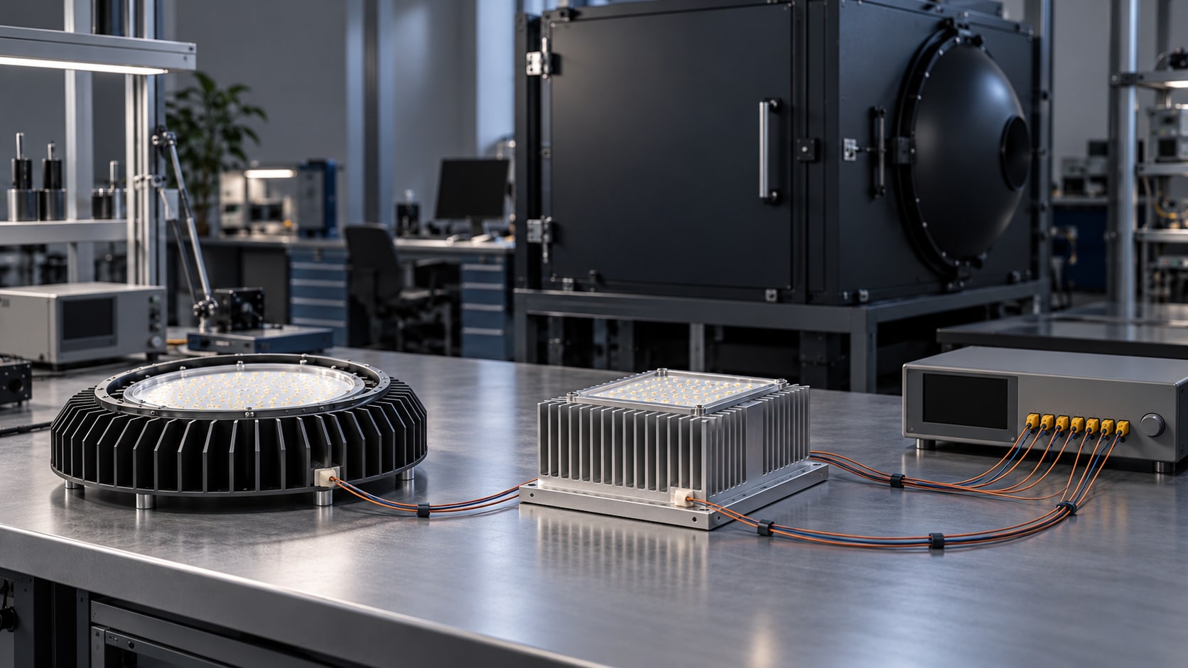
Let’s Solve Your Lighting Thermal Challenge
Tell us about your fixture and operating conditions. Our team will help define a practical next step.