

Vapor Chamber Cooling for Industrial Machine Vision
A 3 mm copper vapor chamber spreads a 300 W processor hotspot across a compact fin assembly, helping a Japanese industrial imaging OEM meet its temperature-uniformity target within a 45 mm height limit.
A Compact Controller for Continuous Vision Processing
The customer needed a thermal assembly for an industrial image-processing platform, with a concentrated processor load and limited room around the PCB.

300 W at the source
A 20 × 20 mm processor contact area concentrates the thermal load into a small footprint.
150 × 150 × 45 mm
The complete cooling assembly must stay within the existing mechanical envelope.
25°C inlet air
The thermal evaluation uses a defined air inlet temperature for repeatable measurements.
160 m³/h installed airflow
Air passes through the fin assembly under the specified test setup.
The Challenge Was Spreading Heat Within a Fixed Envelope
Increasing fin area alone would not address the concentrated heat input, limited assembly height and sensitive mechanical interface.
Concentrated heat input
The 20 × 20 mm source occupies only a small part of the available base area. Heat must spread laterally before the full fin field can contribute.
A strict height budget
The 45 mm assembly envelope leaves little room for a thicker solid base or taller fins. The spreading layer must preserve useful fin height.
A sensitive PCB interface
Contact flatness, clamping load and component clearance must work together, so improved cooling does not introduce board stress or assembly interference.
Clear Acceptance Criteria Before Hardware Release
The project linked thermal uniformity, mechanical fit and interface quality to a defined test and inspection plan.
| Criterion | Project requirement | Verification |
|---|---|---|
| Temperature uniformity | Hotspot-to-perimeter base difference ≤8 K | Measure the hotspot and defined perimeter locations under the same steady-state load. |
| Assembly envelope | 150 × 150 × 45 mm maximum | Check the complete assembly against the controller clearance model. |
| Interface flatness | ≤0.05 mm over a 100 mm span | Inspect the finished contact surface against the drawing datum. |
| Thermal test boundary | 300 W; 25°C inlet; 160 m³/h airflow | Record power, inlet temperature, airflow and sensor locations together. |
Contact integrity
Review the locating features and clamping load with the customer assembly.
Defined comparison
Use the same source area, mounting setup and measurement locations when assessing performance.
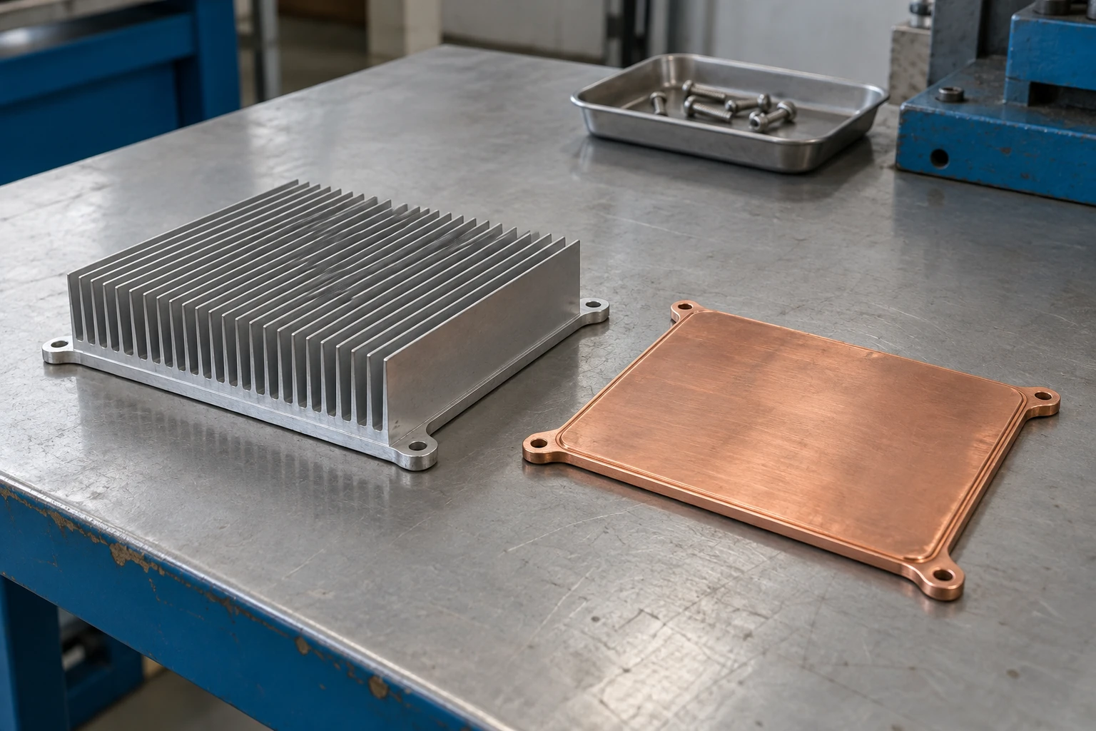
A 3 mm Vapor Chamber at the Heart of the Assembly
morton combined a copper vapor chamber, a precision-located copper contact surface and aluminum fins to spread heat across the available footprint while retaining the low-profile package.
Adapt the spreading layer, contact geometry and fin assembly to your controller.
Explore a Custom Vapor Chamber AssemblyEngineering the Thermal Path and the Mechanical Interface Together
The team reviewed the details that determine whether a thin spreading layer remains effective after it is installed in the real controller.
Resolve chamber support, contact pressure and PCB clearance in one engineering review.
Request a DFM ReviewTest Conditions That Make the Results Reproducible
The validation paired thermal measurements with dimensional and clamping checks, connecting the reported result to a defined source, airflow and installation.
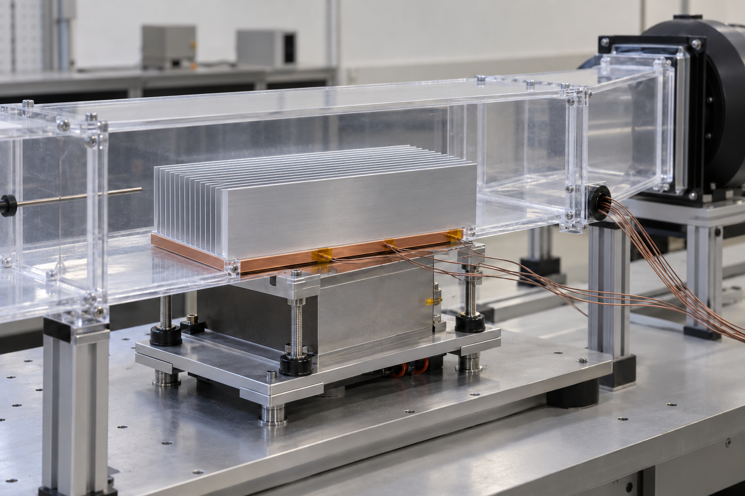
Fix the thermal boundary
Apply 300 W over the 20 × 20 mm source with inlet air at 25°C and 160 m³/h through the assembly.
Map the base temperatures
Measure the base hotspot and defined outer-perimeter locations to evaluate lateral temperature uniformity.
Verify the installation
Complete first-article dimensional checks and clamping-force validation with the specified contact interface.
Connect data to the drawing
Retain sensor locations, assembly revision and mounting conditions with the thermal measurement record.
Align your test setup with the thermal result you need to qualify.
Discuss the Validation PlanMeasured Performance Within the Project Target
The vapor chamber assembly met the specified base-temperature uniformity requirement in the defined forced-air test.
Hotspot-to-perimeter base difference
Measured at 300 W, with a 20 × 20 mm source, 25°C inlet air and 160 m³/h airflow. The reported 67°C is the base hotspot temperature.
Compare your thermal boundary with the conditions behind these results.
Evaluate My Performance TargetFrom 20 Engineering Samples to 800 Production Units
The project progressed from dimensional and clamping validation to first production supply, giving the OEM a compact thermal solution with defined acceptance conditions.
20 engineering samples
Validate dimensions, assembly fit and clamping force before approving the production configuration.
First-article release
Link the approved geometry, contact interface and thermal boundary to the manufacturing and inspection requirements.
800-unit first delivery
Transfer the accepted assembly into the first production order while preserving the approved configuration.
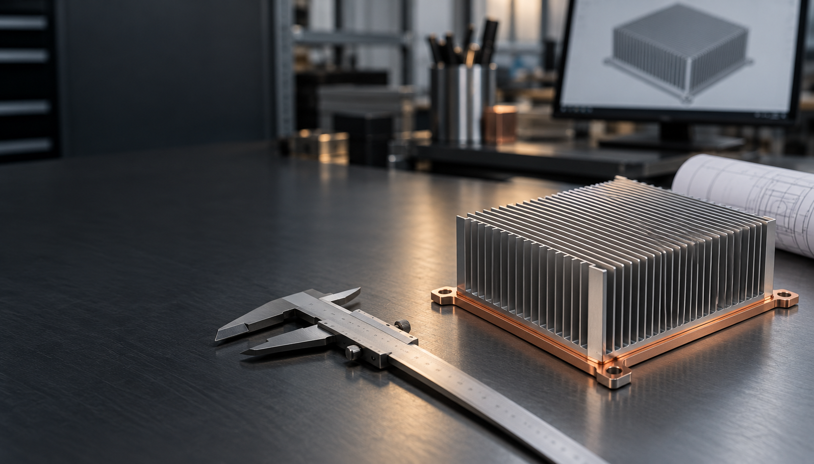
Bring Your Machine Vision Cooling Challenge to morton
Share your heat source, assembly space and cooling conditions. Our engineering team will review the thermal path, mechanical interface and route to a production-ready assembly.
Hotspot-driven design
Define power and source area before selecting the spreading layer.
Mechanical fit
Review chamber support, contact load and PCB clearance together.
Defined validation
Tie thermal performance to the source, inlet air and installed airflow.
Sample-to-production support
Align engineering samples, first articles and controlled production.
One technical contact
Coordinate the drawing, thermal evidence and manufacturing handoff.
Request an Engineering Review
Tell us what your controller needs to dissipate and where the assembly must fit.