
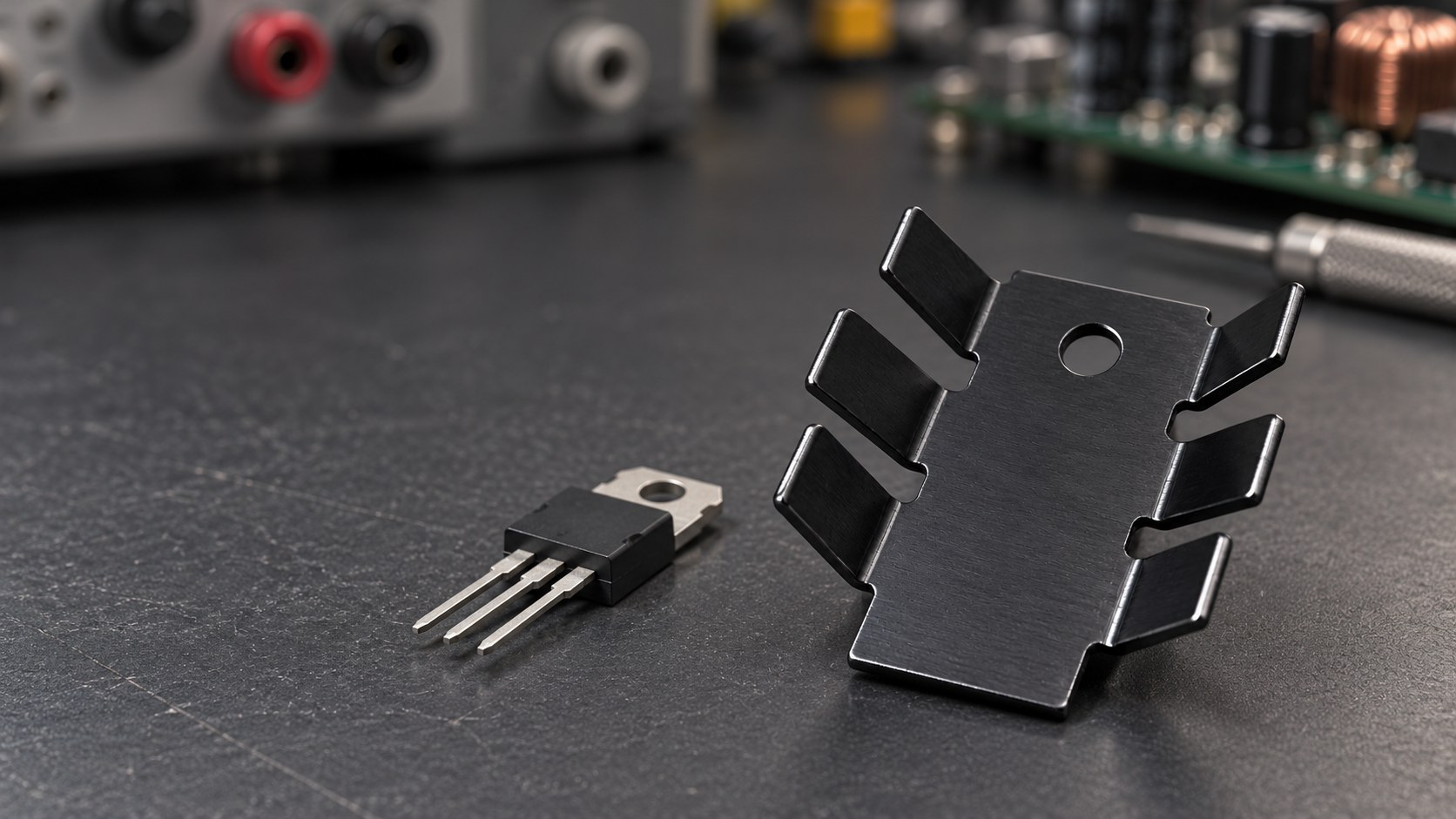
Stamped Heat Sinks. Built for Your Production
Thin-sheet cooling with integrated bends, punched features and mounting details—engineered around your device, airflow and assembly process.
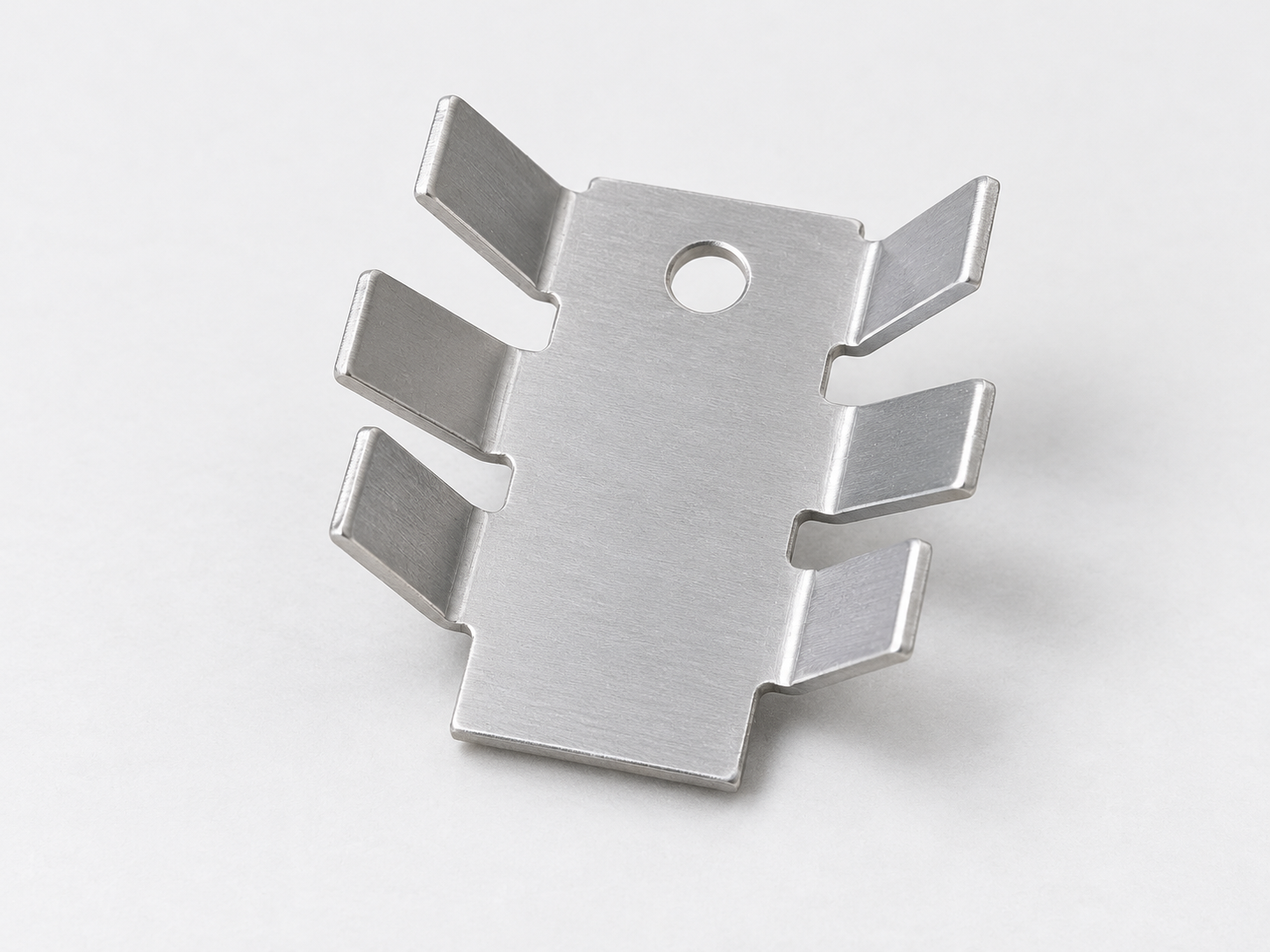
A Small Sheet-Metal Part. A Practical Thermal Path
Stamped heat sinks conduct heat from a discrete device into formed sheet metal, adding exposed surface area without the bulk of a machined block.
Get More Function from Every Formed Feature
Integrating cooling and mounting features into the sheet helps simplify the part and the assembly around it.
Less material to move
Thin aluminum sheet keeps component weight low while providing useful exposed area.
Fewer separate details
Punched holes, tabs and location features can reduce secondary operations.
A better fit in the enclosure
Bends and cut-outs follow the available space and nearby component keep-outs.
A repeatable production route
Controlled tooling and first-piece approval help maintain geometry between batches.
Turn the features you need into a simpler production part.
Explore My Part DesignChoose the Sheet and Finish for the Job
Balance heat spreading, weight, corrosion protection and assembly requirements before freezing the material specification.
| Material | Why choose it | What we review |
|---|---|---|
| 1050 / 1060 aluminum | Low weight and good formability for efficient punched-and-bent geometry. | Sheet temper, bend radius and contact stiffness. |
| Copper sheet | Higher conductivity helps spread heat in a compact footprint. | Mass, springback, oxidation protection and material cost. |
| Specified sheet grade | Match a customer-approved alloy and temper to the drawing. | Material certification and forming feasibility. |
Anodized aluminum
Black or clear anodize can support corrosion protection and appearance; contact and grounding areas are defined on the drawing.
Controlled contact surfaces
Masking and finish selection preserve the intended thermal and electrical interfaces.
Match your material and finish to the actual assembly conditions.
Specify My Material & FinishDefine the Geometry Before You Commit to Tooling
Sheet thickness, bend geometry and mounting position must work together to keep the part formable and the contact area stable.
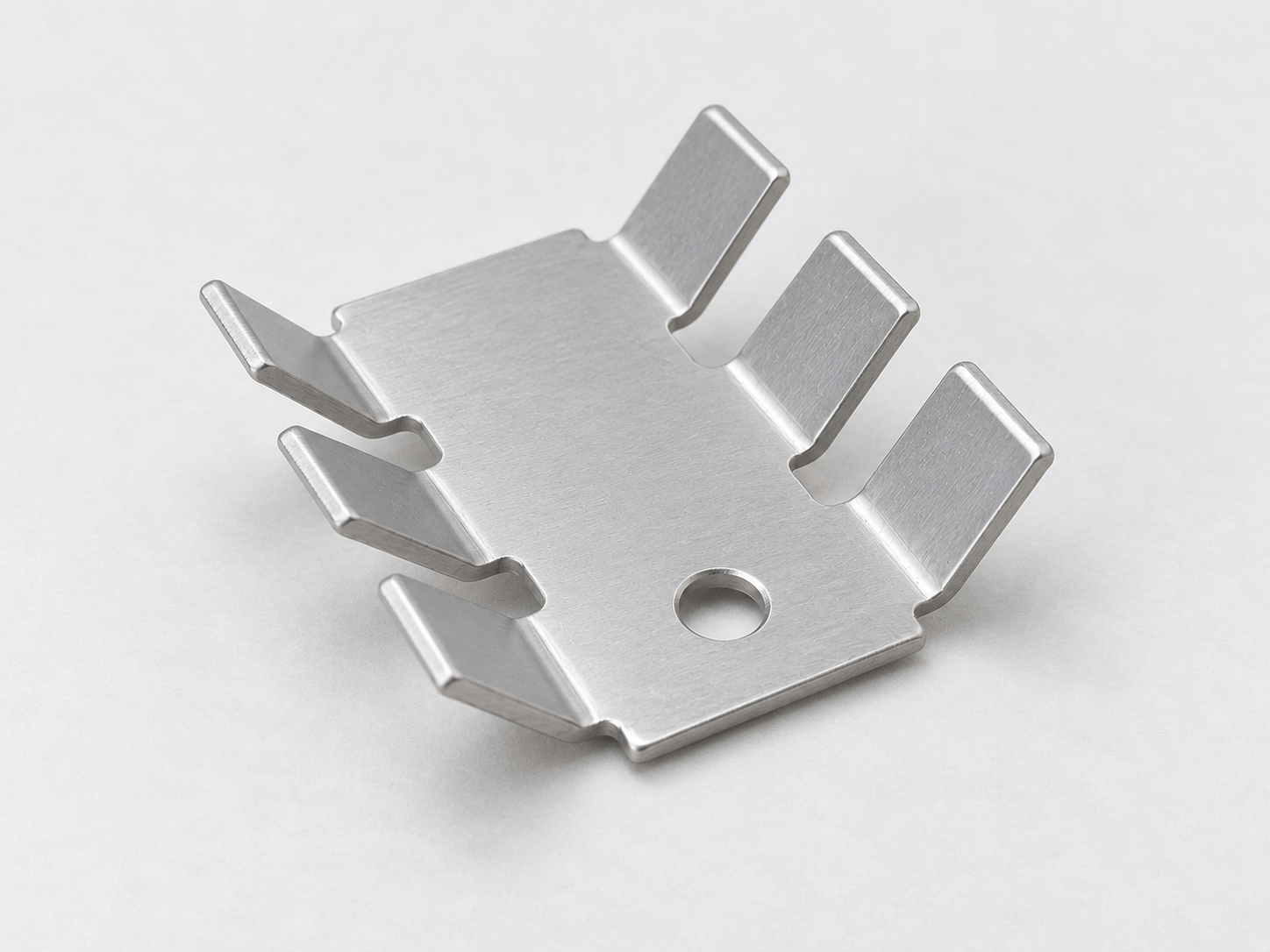
Send your envelope and interfaces for a focused manufacturability review.
Check My DrawingStart with the Thermal Budget
A heat sink is selected from the complete heat path, using the real device loss, inlet air temperature and mounting conditions.
Power dissipation, maximum junction temperature, inlet air temperature, package resistance and interface material.
Confirm temperature rise with the approved mounting pressure, orientation and installed airflow.
Share the operating conditions and we will review the available thermal margin.
Review My Thermal Budget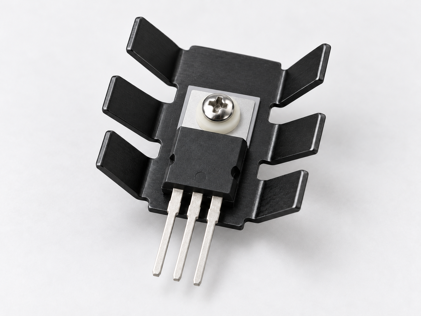
Make the Thermal Contact Easy to Assemble
The device, interface material and mounting hardware need a controlled contact path that also respects electrical clearances.
Review the complete mounting stack before releasing the part.
Discuss My Mounting StackGive the Air a Clear Route
Openings and formed surfaces work best when their orientation matches the air path inside the enclosure.
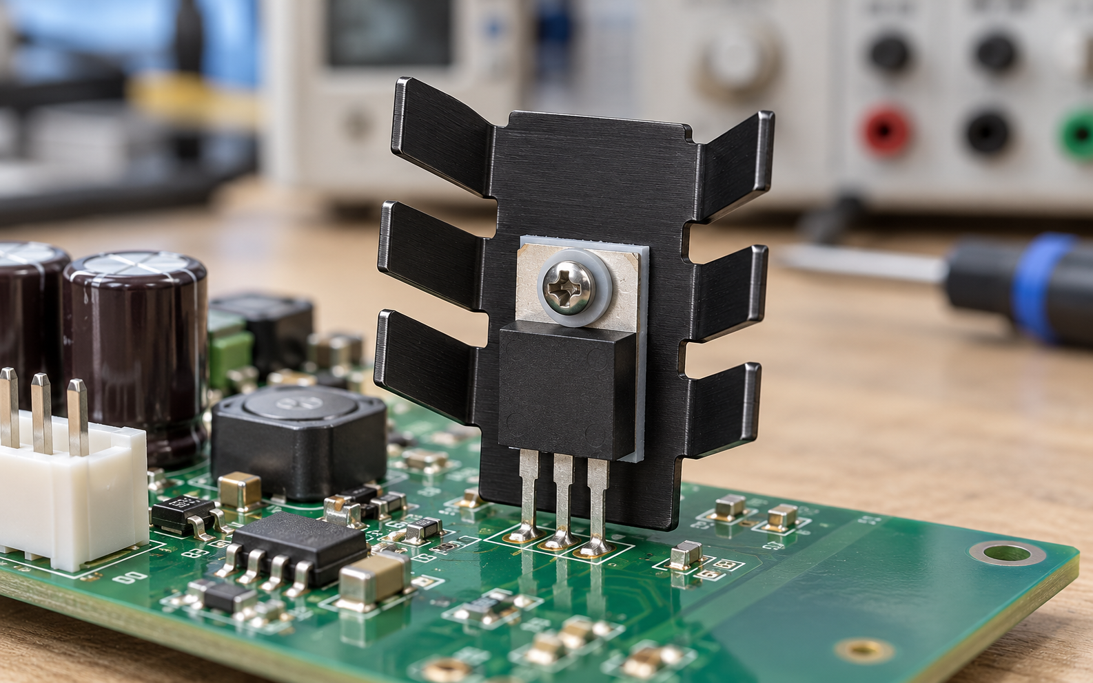
Natural convection
Position the formed channels to let warm air rise. Keep the entry and exit clear of nearby parts.

Forced airflow
Align openings with the installed air stream. Check bypass paths and the fan operating point in the actual enclosure.
Let us review the airflow around your stamped part.
Review My Airflow LayoutFrom Flat Sheet to a Controlled Production Part
Each forming stage carries the functional drawing forward, so the finished part is ready for the next assembly operation.
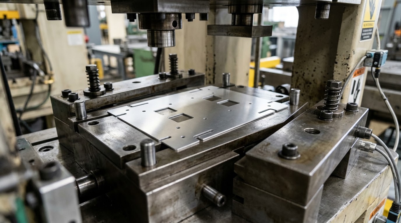
Confirm sheet grade, thickness and batch identification.
Produce the outline, holes and openings with the specified burr direction.
Control bend radius, angle, springback and contact-pad stability.
Remove sharp edges around handling and functional interfaces.
Apply the specified treatment and protect masked contact areas.
Check approved dimensions, appearance, identification and packaging.
Build your inspection requirements into the manufacturing route.
Plan My Production RouteDefine Quality Where It Affects the Assembly
Functional dimensions and agreed thermal checks turn an approved sample into a repeatable acceptance standard.
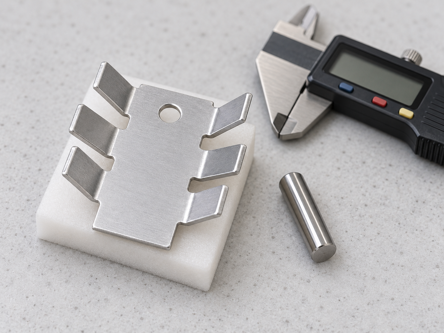
Sheet grade, thickness, condition and material batch records.
Contact footprint, bend angle, hole position, envelope and burr control.
Approved package fit, mounting stack and thermal verification under defined conditions.
FAI, dimensional report, material records, CoC and order-specific compliance information.
Make your critical features visible in the inspection plan.
Define My Quality RequirementsCompact Cooling for Everyday Power Electronics
Stamped cooling fits discrete hot components where space, assembly access and repeat production matter together.
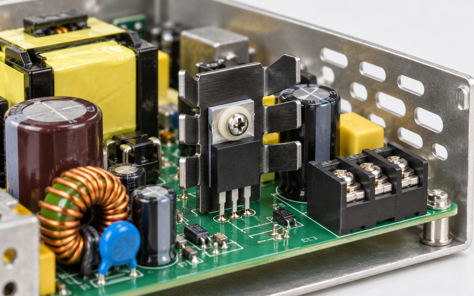
Industrial power supplies
Support rectifiers and switching devices with a compact contact-and-fin structure.
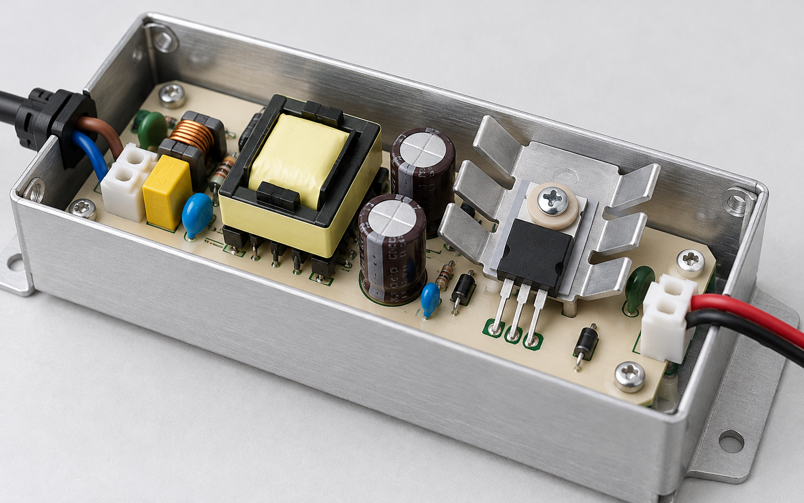
LED driver electronics
Help manage discrete power-device heat inside a space-limited driver assembly.
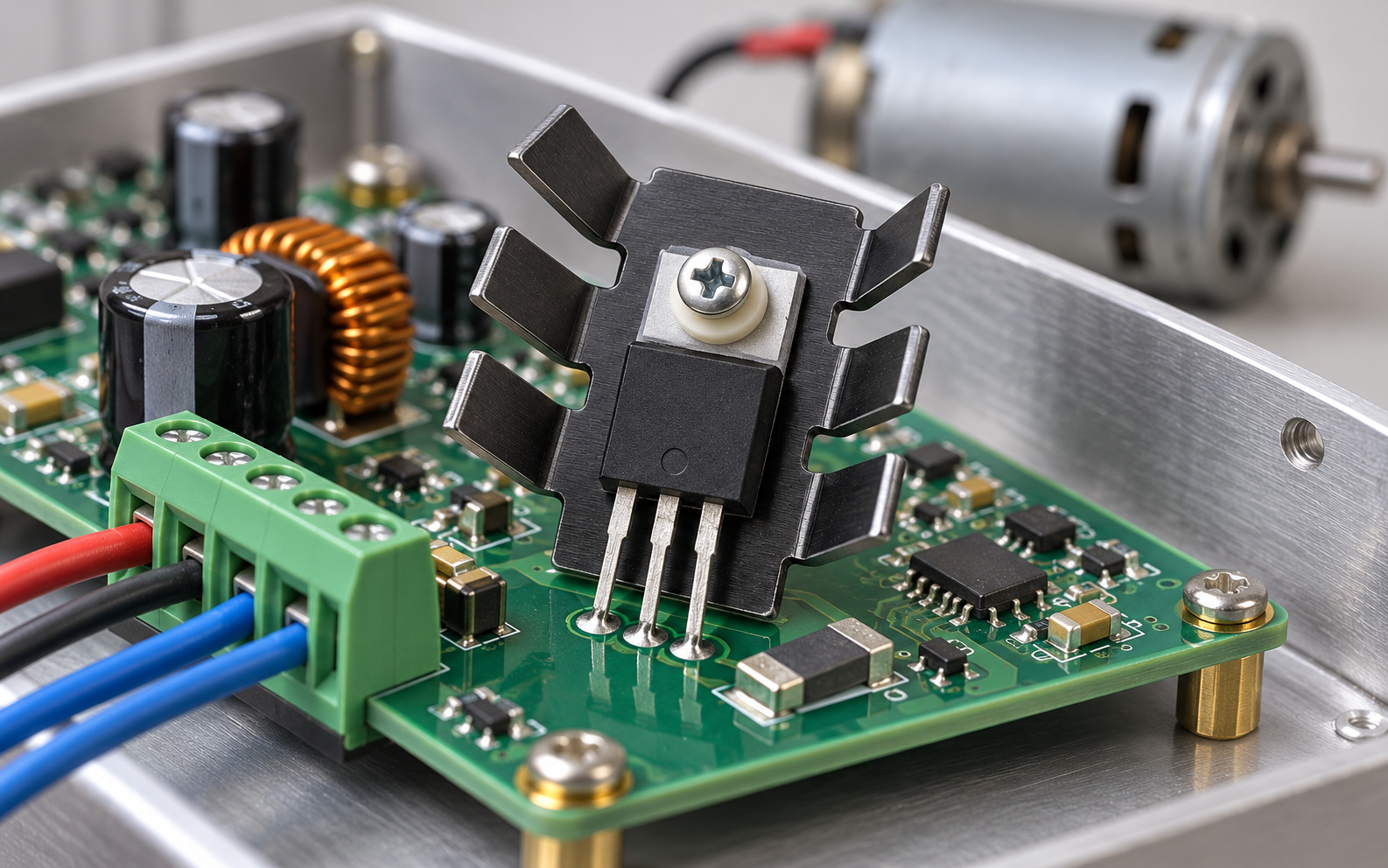
Motor-control boards
Add local cooling around selected power devices without crowding the control electronics.
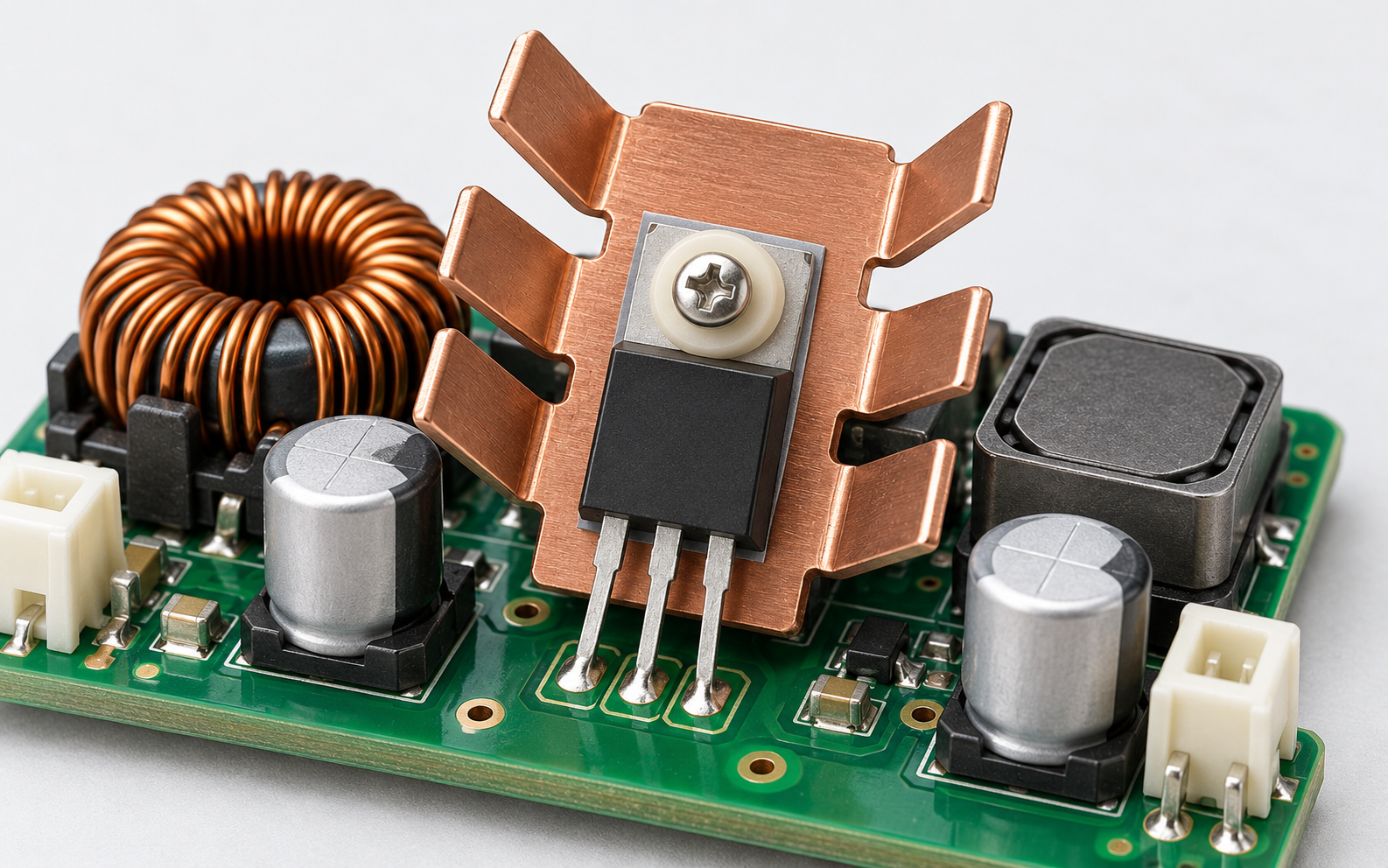
DC/DC conversion
Fit a defined device footprint while preserving lead and service clearances.
Tell us which device gets hot and where it sits in your equipment.
Match My ApplicationBring the Requirements. Leave with a Clear Part Definition
A focused engineering handover reduces avoidable changes between the drawing, the first sample and the production order.
What to send
- 2D drawing or 3D model with key dimensions and tolerances
- Device package and target contact footprint
- Power and ambient conditions (dissipation, inlet temperature)
- Available envelope and PCB component keep-outs
- Annual demand and planned batch sizes
Feasibility review
Check material, bends, holes, keep-outs and tooling approach.
Drawing alignment
Agree functional datums, finish, mounting stack and critical features.
Sample verification
Review dimensional results, fit and the defined thermal test.
Production release
Freeze the drawing revision, control plan, packaging and change process.
Get your engineering and purchasing teams working from the same definition.
Start My DFM ReviewPlan the Tooling, Sample and Repeat Order Together
Separate development decisions from production costs and agree the supply conditions before the first batch.
Engineering samples
- Confirm the tooling route and charged sample scope.
- Conventional drawing-based samples: 10–20 working days after drawing freeze.
- New tooling and first approval: typically 4–8 weeks.
Production quotation
- Separate tooling, material, forming, finishing and inspection costs.
- Compare prices at 100, 500, 1,000 and 3,000 pieces.
- Agree the economic batch size for your approved geometry.
Repeat supply
- Use one controlled drawing revision and approved sample.
- Align rolling forecasts with agreed delivery releases.
- Approve material, process and supplier changes through ECN.
Share your forecast to build a practical sample-to-production plan.
Plan My Supply ScheduleQuestions Before You Freeze the Design
Resolve the details that affect thermal performance, assembly and tooling before the part enters your production BOM.
How much heat can a stamped heat sink dissipate?
When is stamped sheet a good choice?
Can holes, tabs and clips be integrated?
Does black anodizing provide electrical isolation?
Do we need a new tool?
Which files help you quote?
Have a requirement that needs a closer engineering review?
Ask About My Design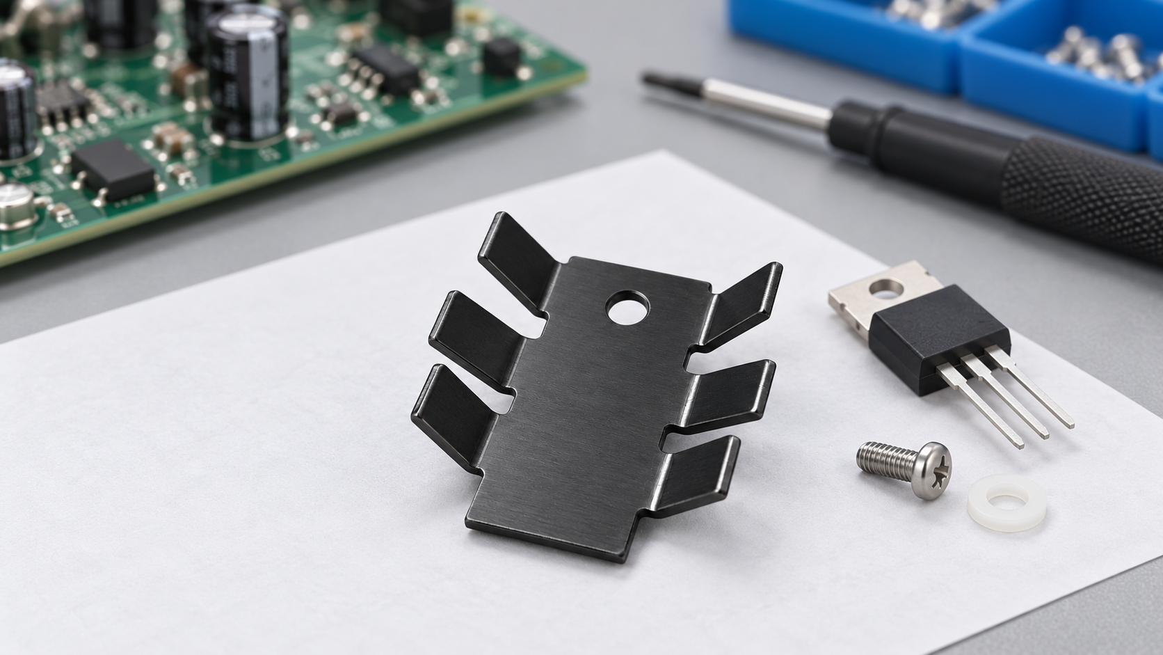
Let’s Shape the Right Stamped Heat Sink
Tell us about the hot device, available space and production plan. We will help define a practical next step.