
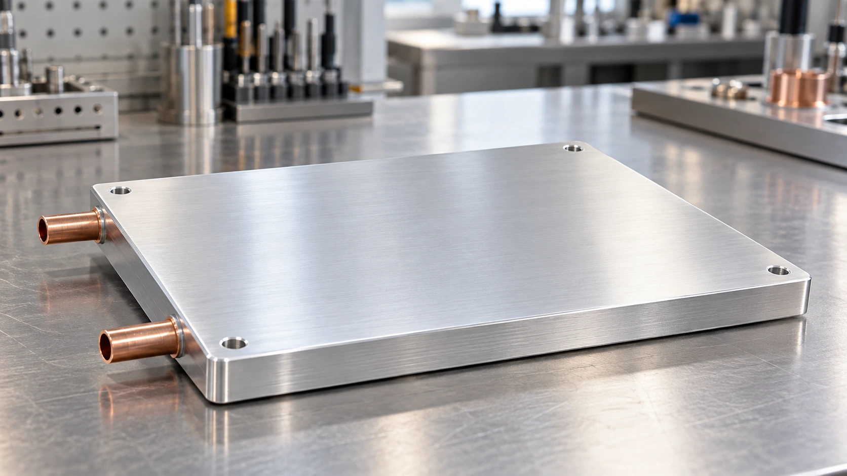
Tube-in-Plate Cold Plates, Engineered Around Your Equipment
Custom aluminum cold plates with embedded copper or stainless steel tubing. Match the heat path, coolant circuit and mounting geometry to your industrial platform.
Bring your heat load and installation envelope into one engineering review.
Discuss Your Cold PlateA Practical Liquid-Cooling Structure
A machined aluminum plate spreads heat into a formed tube, carrying energy into the coolant while keeping the liquid path within the tubing.
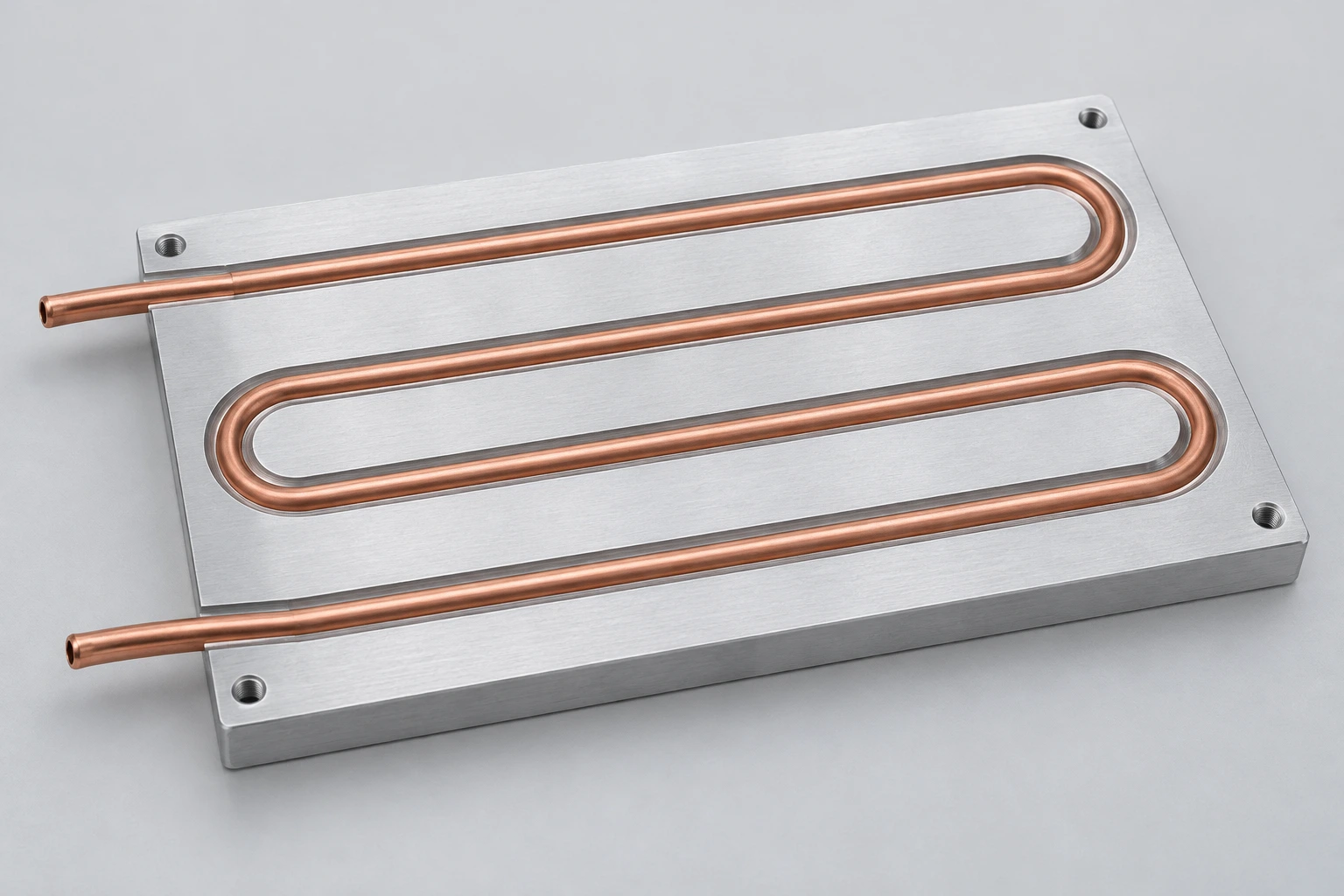
Aluminum heat-spreading base
A 6061 plate provides the mounting structure and distributes heat toward the embedded tube.
Continuous formed tube
Copper or stainless steel tubing creates the coolant path, with tube material selected around the liquid chemistry.
Controlled thermal connection
The groove, tube fit and thermal connection are developed together to reduce resistance between the base and tube.
Start with a structure that fits your thermal and mechanical requirements.
Review Your Plate ConceptControl Every Interface in the Heat Path
Cooling performance depends on the full path from the device mounting surface to the moving liquid.
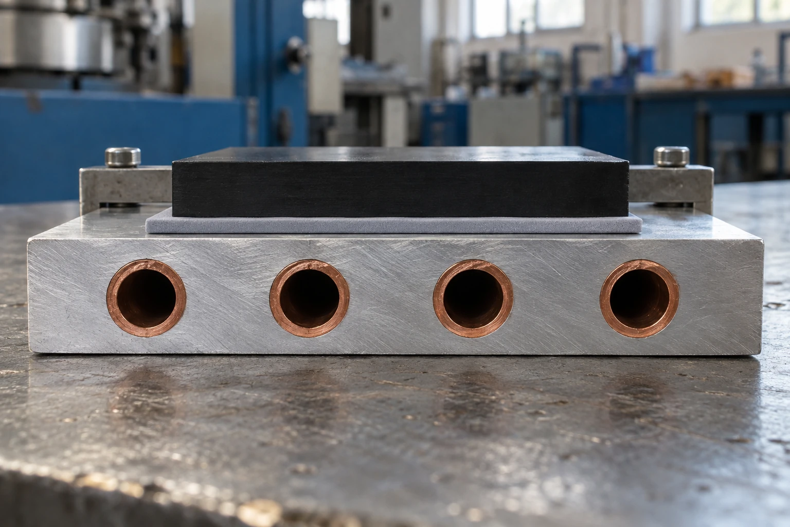
Base spreading
Position the tube path around the heat-source footprint and plate thickness.
Tube connection
Control contact within the groove without damaging the tube wall.
Coolant pickup
Size the circuit around the available flow and allowable pressure drop.
Find the interface that limits your thermal margin.
Discuss the Heat PathRoute the Tube Around the Heat Sources
Align the cooling path with the loaded area while preserving bend radii, mounting clearances and a practical hydraulic circuit.
Cover the active area
Distribute tube passes under the heat sources rather than adding length without purpose.
Respect the tube geometry
Use suitable bend radii and groove support to control thinning, flattening and assembly stress.
Balance temperature and pumping
Review coolant warming along the route together with pressure loss and the pump operating point.
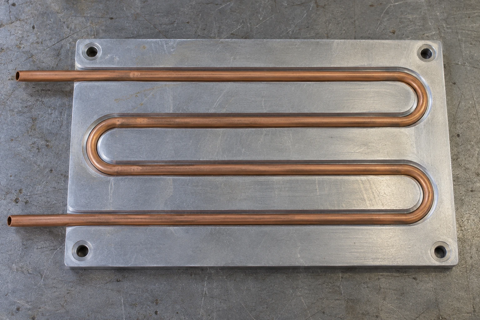
Share a heat-source map to begin the routing review.
Plan Your Tube RouteMake the Cold Plate Fit the Assembly
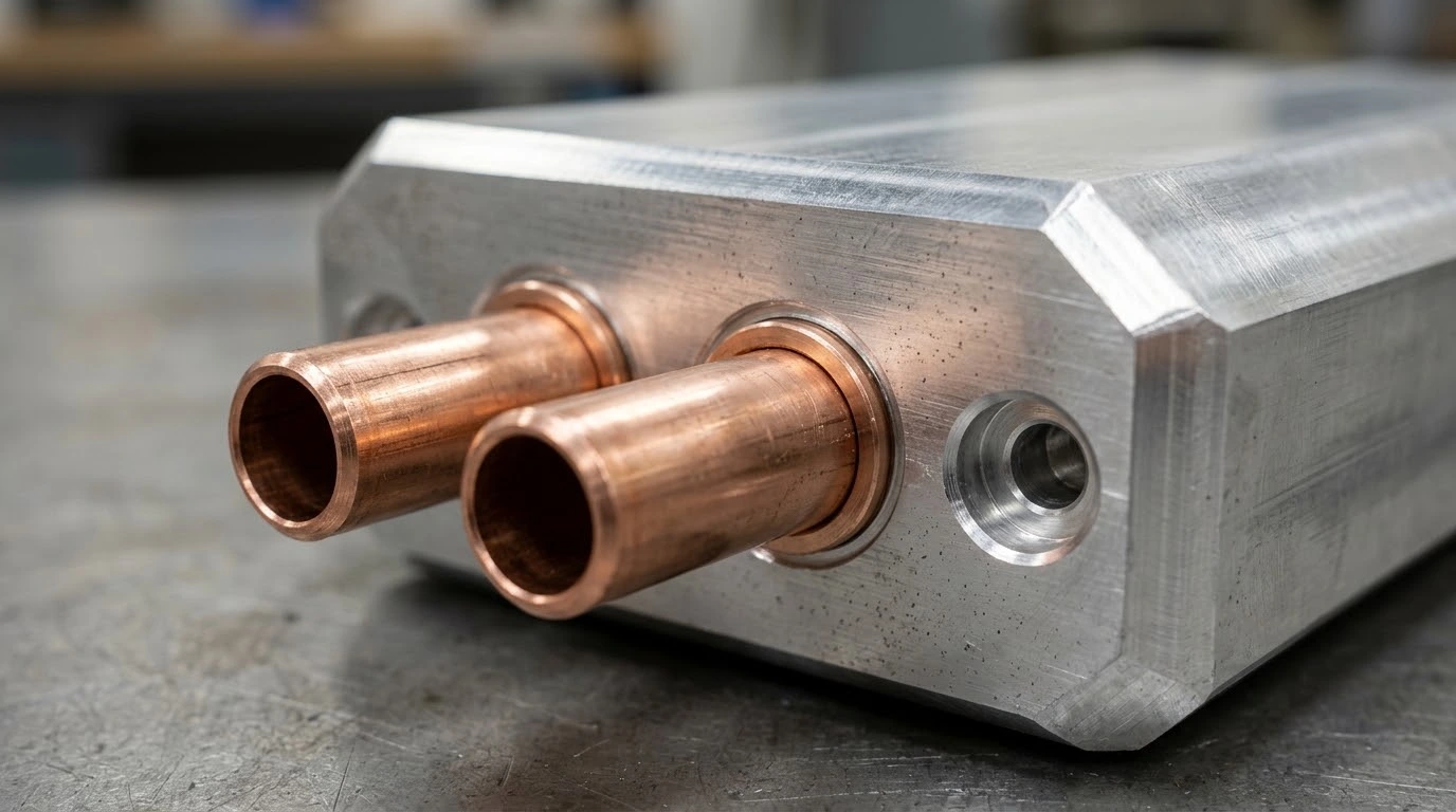
Mounting features and fluid connections are designed together so the plate installs cleanly inside your equipment.
Contact surfaces
Define flatness, surface finish and thermal-interface requirements on the approved drawing.
Mounting features
Locate threads, through holes and datums clear of the embedded tube path.
Tube terminations
Review connection style, orientation, hose access and support loads.
Installation envelope
Check edge clearances, servicing space and the installed tube bend envelope.
Resolve assembly details before the design is released.
Review Your InterfacesSelect the Wetted Material for the Coolant
The tube and fittings define the intended wetted path. Choose them together with the fluid, seals and operating conditions.
Copper tubing
High thermal conductivity supports efficient heat pickup. Confirm compatibility with the coolant formulation and the other wetted metals in the loop.
Stainless steel tubing
Select the stainless grade for the specified coolant chemistry, chloride level and temperature. Account for its lower conductivity in the thermal design.
Coolant Compatibility Engineering Checklist
Choose the tube material around the complete liquid loop.
Check Coolant CompatibilityDefine the Design Window
Start with a clear mechanical envelope, then set the thermal and hydraulic targets around your operating conditions.
Liquid Cooling for Demanding Industrial Platforms
Tube-in-plate structures suit equipment that needs a practical liquid path and a custom mounting footprint.
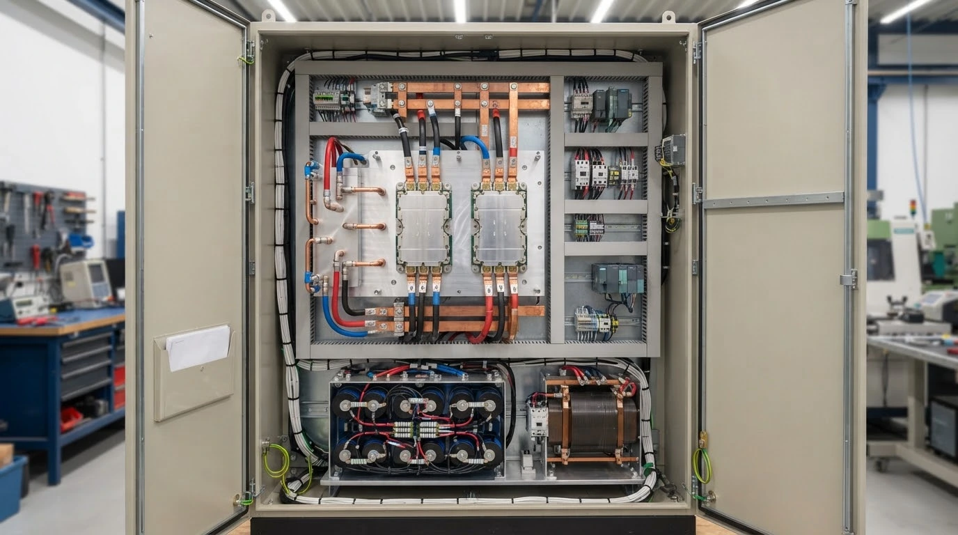
Industrial Drives & Inverters
Cool distributed power devices on a mounting plate shaped around the cabinet and coolant connections.
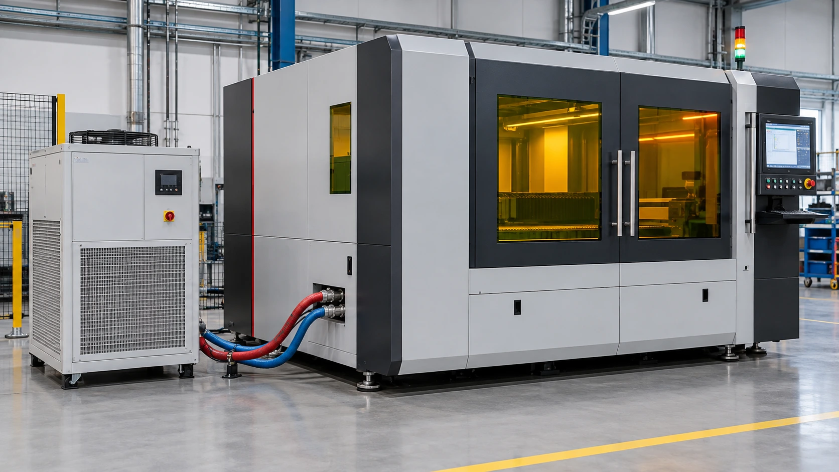
Laser Equipment
Support stable thermal conditions for laser power electronics and auxiliary heat loads.
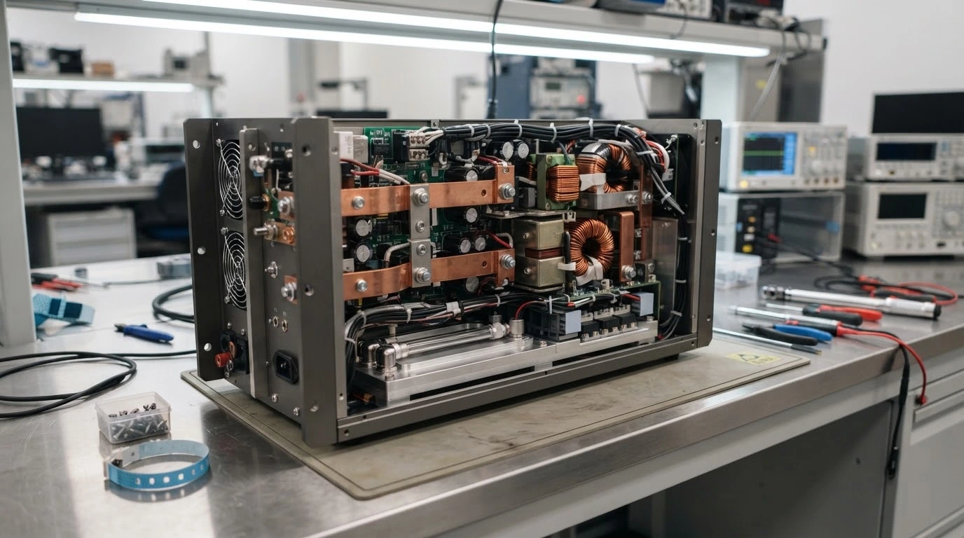
Industrial Power Supplies
Bring liquid cooling into compact, enclosed power-conversion assemblies.
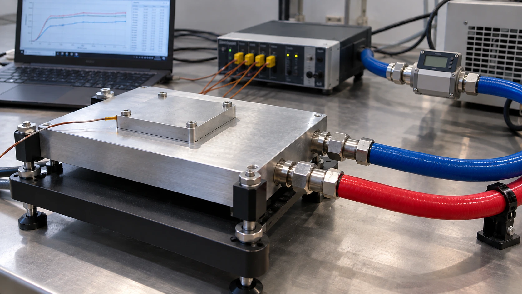
Test & Measurement Systems
Provide repeatable mounting and a controlled cooling path for laboratory and production test hardware.
Validate Thermal Performance and Pressure Drop Together
A useful performance report connects temperatures, heat load and coolant conditions to the same physical test setup.
All thermal and hydraulic test results correlate directly with documented engineering parameters. Data is captured without extrapolated assumptions:
- ■ Tbase, hotspot: Maximum calibrated thermocouple reading directly under the active heat source.
- ■ Tcoolant, inlet: Fluid temperature monitored immediately upstream of the cold plate inlet manifold.
- ■ Qeffective: Net dissipated thermal wattage verified by electrical heater power and fluid calorimetry.
Temperature and load
Record the heat-source layout, effective heat input and stabilized base temperatures.
Coolant conditions
Identify the fluid, inlet temperature and measured flow rate.
Plate pressure drop
Measure at the plate inlet and outlet, excluding external hoses, filters and pumps.
Repeatable setup
Keep sensor positions, mounting force and interface material consistent between tests.
Turn your thermal target into a repeatable acceptance method.
Define Your Validation PlanFrom Machined Groove to Finished Cooling Assembly
Controlled forming, fit and finishing help the approved design become a repeatable manufactured part.
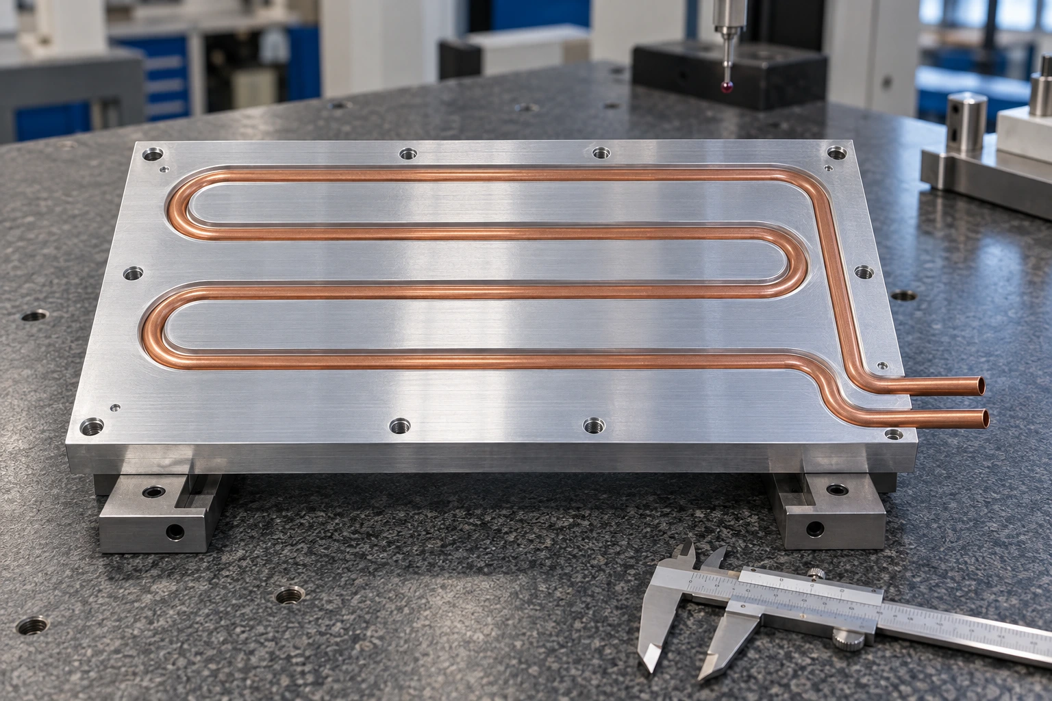
01 · Machine the base
Create the groove, mounting features and controlled datums from the approved drawing.
02 · Form the tube
Control the route, bend quality and end positions before assembly.
03 · Integrate the thermal path
Install the tube with the specified fit and thermal connection while protecting tube integrity.
04 · Finish and verify
Inspect the mounting surfaces, connections and assembly before pressure and leak testing.
Review the manufacturing route before prototype release.
Request a DFM ReviewPressure-Tested, Leak-Checked and Traceable
Define the acceptance criteria on the drawing and connect each released assembly to its inspection records.
Proof pressure
Hydraulic proof testing follows the approved working pressure, hold time and deformation criteria.
Final leak check
Drain, clean and dry the assembly before the specified dry-gas leak test.
Critical dimensions
Inspect tube exits, mounting locations and contact-surface characteristics against the drawing.
Batch traceability
Link materials, work orders and test records for repeat orders and quality investigations.
Make acceptance criteria part of the design package.
Discuss Your Quality PlanOne Engineering Path from Concept to Approved Sample
Connect thermal design, mechanical integration and manufacturing review before committing to production.
What you share
Heat load and source layout; coolant and flow; temperature targets; space and mounting drawings; expected quantity.
What we develop
Tube-route proposal; 2D and 3D design; material and interface specifications; DFM feedback; prototype and validation plan.
Start with your drawing or an early equipment concept.
Start an Engineering ReviewCarry the Approved Design into Repeat Production
Keep the material, drawing revision, inspection plan and packaging aligned from sample approval to scheduled supply.
Sample approval
Confirm the geometry, test conditions and first article results before release.
Controlled production
Use the approved specification, traceable records and agreed change-control process.
Planned delivery
Coordinate batch quantities, protective packaging and the documents needed for your receiving inspection.
Build a supply plan around your equipment program.
Plan Your Production OrderTube-in-Plate Cold Plate Questions
Resolve the key design and sourcing points before you start a custom project.
When is a tube-in-plate structure a good fit?
Can the tube route and mounting holes be customized?
Should I choose copper or stainless steel tubing?
Can you support cooling on both sides?
Which performance information should I provide?
Can I begin with a small prototype quantity?
Bring the remaining design questions to our engineering team.
Ask About Your Project
Let’s Engineer Your Tube-in-Plate Cold Plate
Share your thermal targets and installation requirements. We will review the heat path, tube circuit and production needs with you.
Request an Engineering Review
Tell us what your equipment needs.