
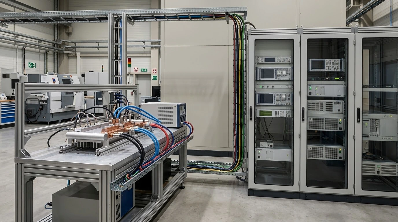
Hybrid Liquid Cooling Assembly for Power Test Equipment
A compact dual-path assembly carries 2.0 kW of primary heat through liquid cooling while a dedicated air path manages 150 W of auxiliary heat.
Bring your heat loads, installation envelope and cooling conditions into one engineering review.
Discuss Your Cooling AssemblyTwo Heat Loads. One Fixed Equipment Envelope
A Netherlands power test equipment OEM needed a cooling assembly that could fit its mechanical layout and keep primary and auxiliary circuits within their thermal limits.
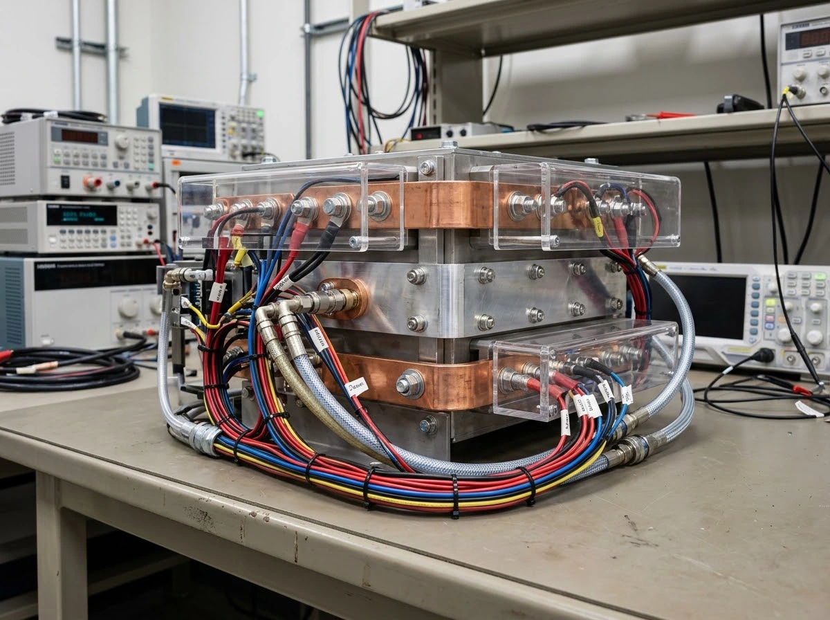
The application brief
The main power module and nearby auxiliary electronics needed different cooling paths. Morton developed a coordinated assembly around the customer’s heat-source positions, installation interfaces and available utilities.
Define the thermal and mechanical boundaries before choosing a cooling route.
Review My ApplicationSolving the Main Hotspot Was Only Half the Task
The design had to remove concentrated power loss without leaving auxiliary devices, pipe routing or service access unresolved.
Concentrated primary load
A 2.0 kW heat source over a 100 × 100 mm contact area required a short, controlled path into the liquid cold plate.
A separate auxiliary burden
150 W of nearby electronics still needed a defined air-cooling route during simultaneous operation.
A constrained mechanical package
The liquid plate, auxiliary heat sink and installation features had to stay within 350 × 400 × 90 mm.
| Thermal | Validate main and auxiliary contact temperatures at simultaneous load. |
| Hydraulic | Record cold-plate pressure drop at the specified 8 L/min operating point. |
| Integration | Provide routing, mounting and overtemperature interlock installation interfaces. |
One Assembly, Two Purpose-Built Cooling Paths
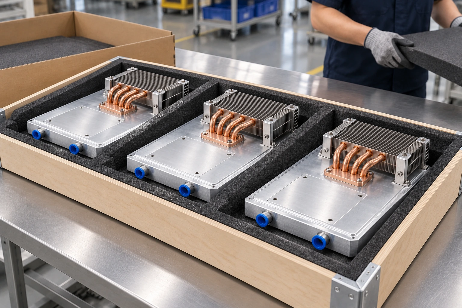
A friction stir welded cold plate serves the main power module, while a separate fin-and-heat-pipe assembly carries heat away from auxiliary devices.
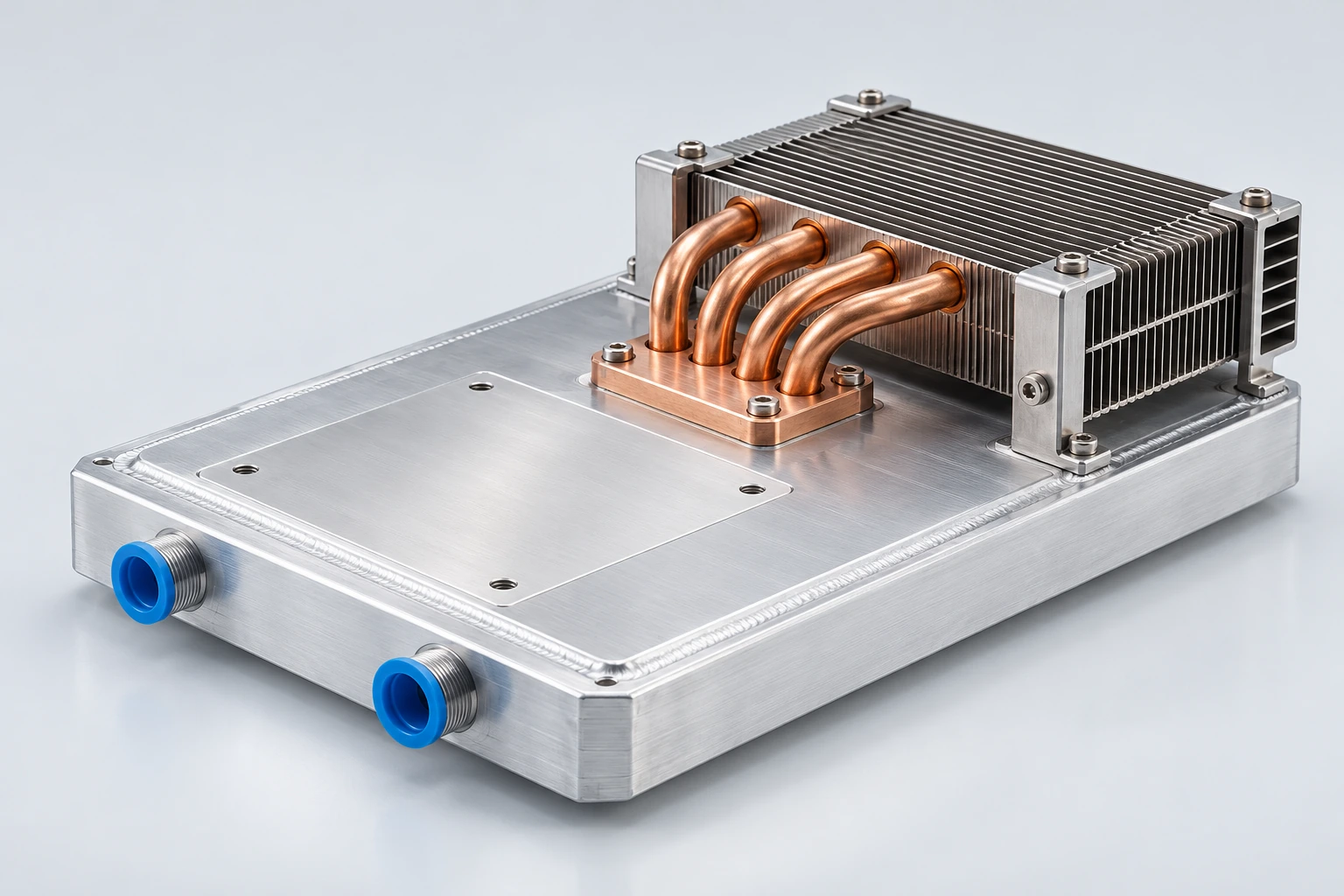
Liquid-cooled main baseplate
Machined flow passages and a welded cover form the primary heat-removal path beneath the power module.
Independent auxiliary heat sink
A dedicated fin pack and heat pipes preserve an air path for the 150 W auxiliary circuit.
Coordinated installation interfaces
Mounting points, coolant connections and interlock installation provisions are developed around the equipment layout.
Separate Heat Paths Keep the Whole Assembly in Balance
Each source is connected to a cooling path matched to its load, with flow and airflow specified at the installed operating point.
Primary liquid path · 2.0 kW
Auxiliary air path · 150 W
Make every watt follow a defined path from source to coolant or air.
Review My Cooling ArchitectureEngineered for Contact, Routing and Repeatable Assembly
The thermal concept becomes a usable component through controlled contact surfaces, accessible connections and a clear installation drawing.
Controlled thermal contact
The main contact region is aligned to the 100 × 100 mm heat source, with interface material and clamping conditions tied to the assembly specification.
Managed coolant routing
Connection locations support hose clearance, filling and venting without compromising the surrounding electrical layout.
Protected auxiliary airflow
The fin pack, heat-pipe routing and guide features preserve an unobstructed path at the installed 90 m³/h airflow.
Defined protection interfaces
Overtemperature interlock installation provisions support the equipment’s sensing and low-flow derating strategy.
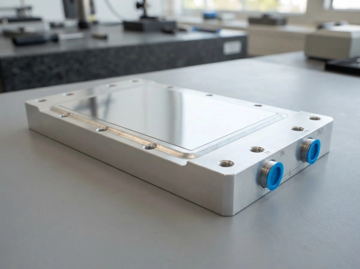
Resolve mechanical interfaces before the first assembly reaches your production line.
Start an Interface ReviewPerformance Verified with Both Heat Sources Operating
The primary and auxiliary results were recorded under simultaneous load, with liquid and air conditions specified separately.
| Main heat load | 2.0 kW |
| Main heat-source contact | 100 × 100 mm |
| Inlet water / flow | 30°C / 8 L/min |
| Main hotspot-to-inlet resistance | 0.017 K/W |
| Auxiliary heat load | 150 W |
| Inlet air / actual airflow | 30°C / 90 m³/h |
A Repeatable Thermal Design Needs a Controlled Liquid Boundary
The manufacturing release plan connects weld quality, cleanliness, pressure testing and part identification to the approved component specification.
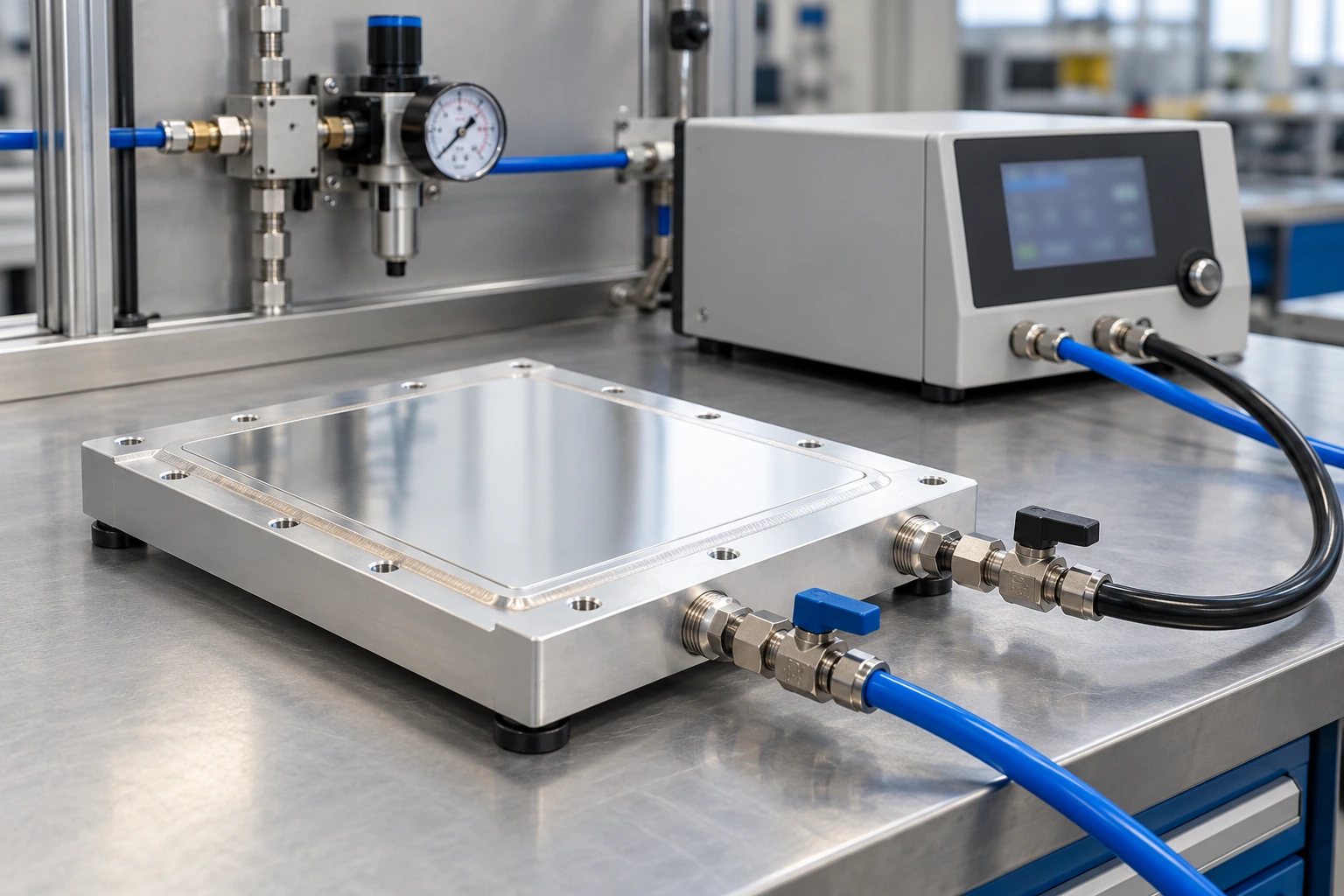
Hydrostatic proof test
For a 0.3 MPa rated industrial design, the standard plan uses 0.6 MPa for 10 minutes, with no leakage or permanent deformation.
Dry gas leak check
After draining, cleaning and drying, stabilized dry air or nitrogen testing is performed to the agreed acceptance limit.
Critical interface inspection
Contact surfaces, mounting features, connection geometry and flow-path cleanliness are checked against controlled drawings.
Traceable release records
Material lots, production records, inspection results and component identification remain linked for the delivered batch.
From a 20-Set Pilot to 120 Production Assemblies
The project moved from trial production into a first delivery with a defined cooling architecture, operating conditions and repeatable component specification.
Confirm assembly fit, thermal performance and production readiness.
Release the approved assembly for the customer’s power test equipment.
Defined operating range
Main and auxiliary cooling conditions, low-flow derating and interlock interfaces documented together.
Controlled component package
Drawings, mounting details, material specifications and inspection requirements tied to the approved revision.
Repeatable supply
Traceable batches and protected cooling surfaces support equipment assembly and future replenishment.
Turn a successful prototype into a component your team can procure repeatedly.
Plan My Pilot Build
Bring Your Power Test Cooling Challenge to Morton
Share your heat-source layout, available space and cooling conditions. Our engineering team can help define a hybrid assembly around the way your equipment actually operates.
Discuss Your Cooling Requirements
Tell us the key conditions for your application.