
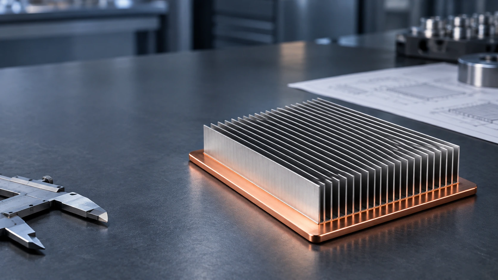
Spread the Heat. Unlock Your Design
Custom vapor chamber heat sinks distribute concentrated heat across the fin base, helping compact electronics stay within their thermal limits.
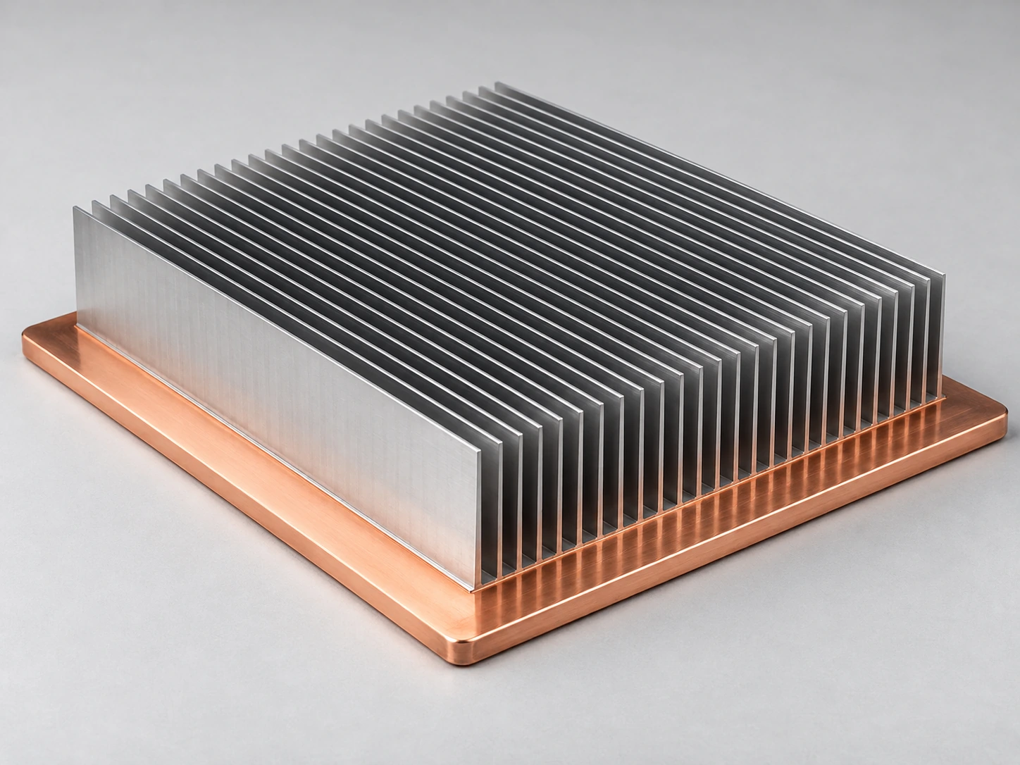
What Is a Vapor Chamber Heat Sink?
A sealed copper-water chamber spreads heat in two dimensions before the fin array transfers it to the surrounding air.
Evaporation and condensation move energy away from a concentrated source.
More of the base participates in heat transfer when the fin array and airflow are properly matched.
Chamber, fins, contact surface and mounting features are developed around your equipment.
Solve the Hotspot Before It Limits the System
A vapor chamber addresses spreading resistance where a small heat source meets a much larger heat sink.
Concentrated chip power
Distribute heat beyond the device footprint so the outer fin area can do useful work.
Uneven base temperature
Reduce local temperature gradients with a chamber sized around the actual source layout.
Restricted installation height
Use a planar spreading layer to make better use of the available stack height.
Several heat sources
Coordinate source positions, support points and fin coverage within one assembly.
Start with the thermal bottleneck in your current design.
Talk Through Your HotspotA Continuous Cycle Inside a Sealed Chamber
Water circulates through evaporation, vapor transport, condensation and capillary return without an external pump.
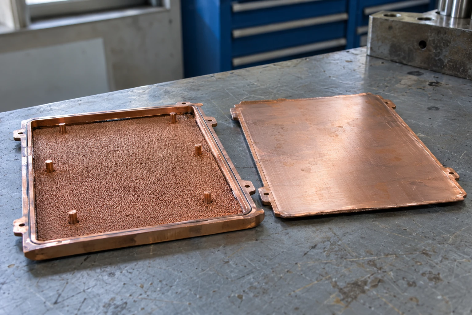
Precision planar copper-water chamber: heat vaporizes liquid at the hotspot, travels rapidly through the low-pressure core, condenses across the fin base, and returns via capillary force.
01 · Evaporate
The working fluid absorbs heat at the source and turns into vapor.
02 · Spread
Vapor moves through the internal space toward cooler regions.
03 · Condense
Heat passes through the chamber wall into the fin assembly.
04 · Return
The wick draws liquid back to the heated area by capillary action.
Match chamber geometry and wick performance to your operating conditions.
Discuss Chamber DesignPerformance You Can Evaluate in Context
A defined test setup turns thermal resistance into a useful engineering decision.
Two-phase spreading distributes concentrated heat across a wider fin base, helping reduce local temperature gradients under the stated test conditions.
- Assembly Size 150 × 150 × 45 mm finished sink
- Vapor Chamber 3 mm planar copper-water core
- Heat Source 20 × 20 mm centralized heater block
- Airflow Rate 160 m³/h through assembly duct
- Ambient Inlet 25 °C constant air inlet
- Applied Power 300 W steady continuous load
Evaluate your design using the same source, airflow and measurement conditions.
Request a Thermal ReviewA Practical Envelope for Custom Development
Start with the chamber footprint, thickness and finished assembly height, then refine the geometry around your interfaces.
Share the installation envelope and critical dimensions.
Check Your Design EnvelopeThin Profiles Need Deliberate Structural Design
Thermal spreading, chamber support and mounting loads must work together inside the available height.
Source placement
Locate the evaporator region around the actual chip footprint and power map.
Internal support
Coordinate support points with vapor space, local stiffness and mounting loads.
Height allocation
Balance chamber thickness, fin height, board clearance and usable airflow.
Orientation and startup
Verify performance at the installed angle and expected startup temperature.
Review the thermal stack before freezing the mechanical layout.
Review Your Stack-UpTurn Better Spreading into Useful Air-Side Cooling
The chamber and fin array are developed as one thermal path, using the airflow available inside your equipment.
Fin geometry
Select height, spacing and material around the required surface area and pressure drop.
Installed airflow
Use the fan operating point and measured flow through the sink, including duct restrictions.
Controlled attachment
Specify the chamber-to-fin connection and inspect joint consistency.
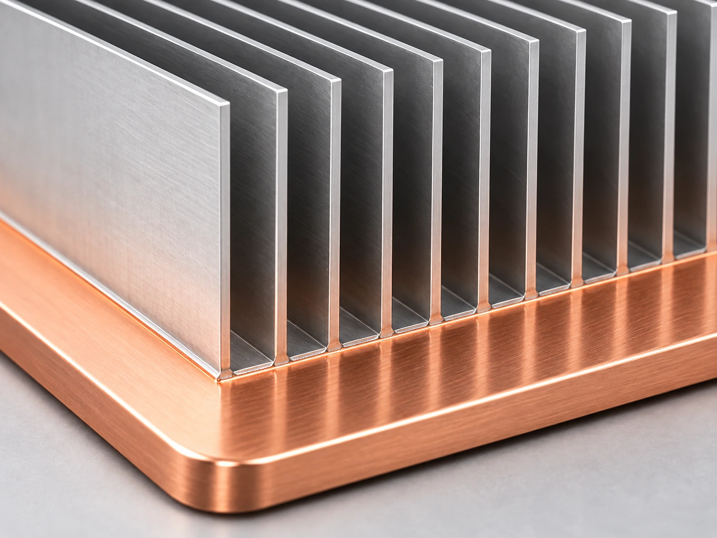
Fin Pitch & Boundary Layer
Optimized fin spacing to prevent boundary layer interference under low-to-medium static pressure.
Ducting & Bypass Sealing
Ducting and bypass seals direct air through the fin channels. Verify through-fin airflow and pressure drop at the installed fan operating point.
Solder Joint Integrity
Control solder coverage, bond-line thickness and voiding against the approved acceptance criteria to limit added interface resistance.
Bring the fan curve and duct layout into the discussion.
Optimize Chamber and AirflowProtect the Contact Path and the Chamber
A controlled interface keeps heat transfer repeatable while protecting the device, PCB and sealed chamber.
Flat contact surface
Define contact flatness and surface finish on the finished assembly. Precision interfaces can be reviewed to ≤0.05 mm flatness over 100 mm.
Matched interface material
Choose TIM thickness and compression from the gap, load limit and thermal resistance target.
Controlled clamping
Use approved brackets, spring screws or stops to distribute load. Mounting holes stay outside the sealed cavity unless designed into its perimeter.
Share the device load limit, contact area and mounting drawing.
Review Interface and MountingBuilt Around Compact Electronics with Demanding Hotspots
Vapor chamber heat sinks are a useful option when concentrated heat must reach a larger fin area within a restricted envelope.
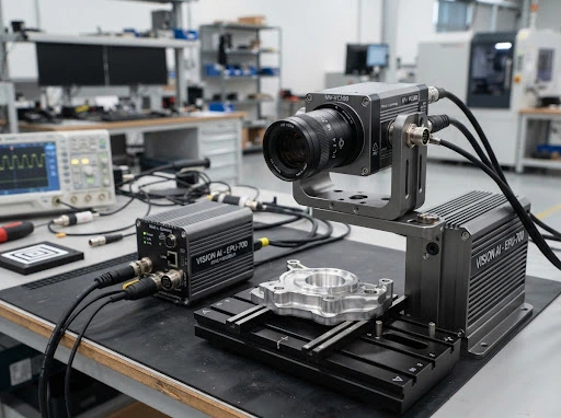 Precision Automation
Industrial Vision
Spread processor heat across a low-profile cooling assembly without crowding adjacent boards.
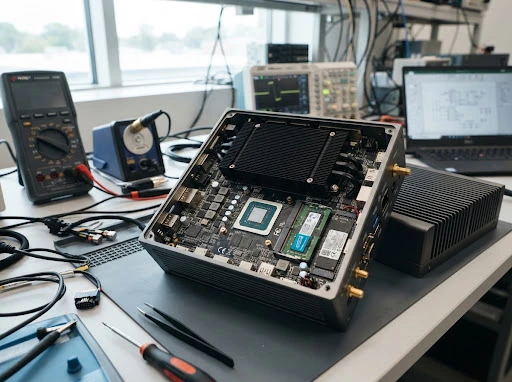 Embedded Compute
Edge AI Computing
Manage concentrated compute loads within a compact, serviceable air-cooled enclosure.
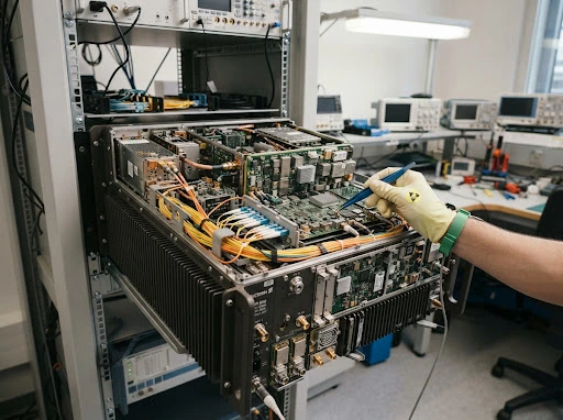 RF & Infrastructure
Telecom Equipment
Distribute local heat across a wider fin base under the equipment’s installed airflow.
 Datacenter 1U / High-Density
Server Electronics
Evaluate a chamber-based solution where dense sources and height limits make spreading resistance significant.
Tell us how your electronics are packaged and cooled.
Discuss Your EquipmentCustomize the Interfaces That Decide the Fit
The finished assembly is developed around your thermal map, enclosure and production requirements.
Footprint and thickness
Fit the spreading area to the source map and mechanical envelope.
Contact geometry
Define source contact, surface finish and protected interface areas.
Fin configuration
Coordinate material, spacing, height and connection method.
Mounting features
Position brackets, keep-outs and load paths around the sealed chamber.
Surface protection
Specify nickel plating or other compatible treatments where appropriate.
Assembly and marking
Control supplied hardware, labeling, packaging and drawing revision.
Send a STEP model, drawing or a clear installation sketch.
Start a Custom Design ReviewControl the Details from Chamber to Finished Assembly
Incoming screening, controlled assembly and defined verification help keep production aligned with the approved sample.
Screen the chamber
Check incoming thermal response and consistency against the agreed specification.
Control assembly
Manage fin attachment, contact geometry, fixtures and critical process settings.
Verify the assembly
Inspect key dimensions and perform thermal sampling using approved conditions.
Release with traceability
Link material lots, work orders, inspection results and drawing revisions.
Define the critical characteristics before production starts.
Discuss Your Quality PlanMove from Thermal Review to Repeat Supply
A single project team coordinates design, sampling, approval and scheduled production for your vapor chamber assembly.
Engineering review
Confirm power, source map, envelope, airflow and acceptance criteria.
Prototype and test
Joint development commonly takes 4–8 weeks for first samples and testing.
Approve and freeze
Release the drawing, sample, BOM and inspection requirements together.
Schedule repeat supply
Typical chamber assembly production lead time is 30–45 days after approval and order conditions are met.
Plan the sample, validation and production milestones together.
Plan Your ProjectQuestions Engineers Ask Before Specifying a Vapor Chamber
Clarify the operating conditions and integration details that determine whether a chamber-based heat sink is the right route.
When is a vapor chamber useful?
When a small or unevenly loaded heat source needs to use a much larger cooling area and base spreading resistance is significant.
Does it replace the fins or the fan?
No. The chamber spreads heat; fins and available airflow still reject that heat to the air.
Will it work in every orientation?
The wick supports capillary return, but capacity depends on geometry, source position, operating temperature and installation angle. Verify the intended orientation.
Can mounting holes pass through the chamber?
Only through features deliberately designed and sealed for that purpose. Do not drill or machine the sealed cavity after manufacture.
What should I send for a design review?
Send heat load, source size and position, target temperature, inlet air temperature, installed airflow, space limits, mounting details and annual volume.
How do you validate the thermal resistance?
Define the heat source, effective load, inlet temperature, measured airflow, orientation, interface and sensor positions. Compare results only under equivalent conditions.
Have a question specific to your layout?
Ask Our Engineering Team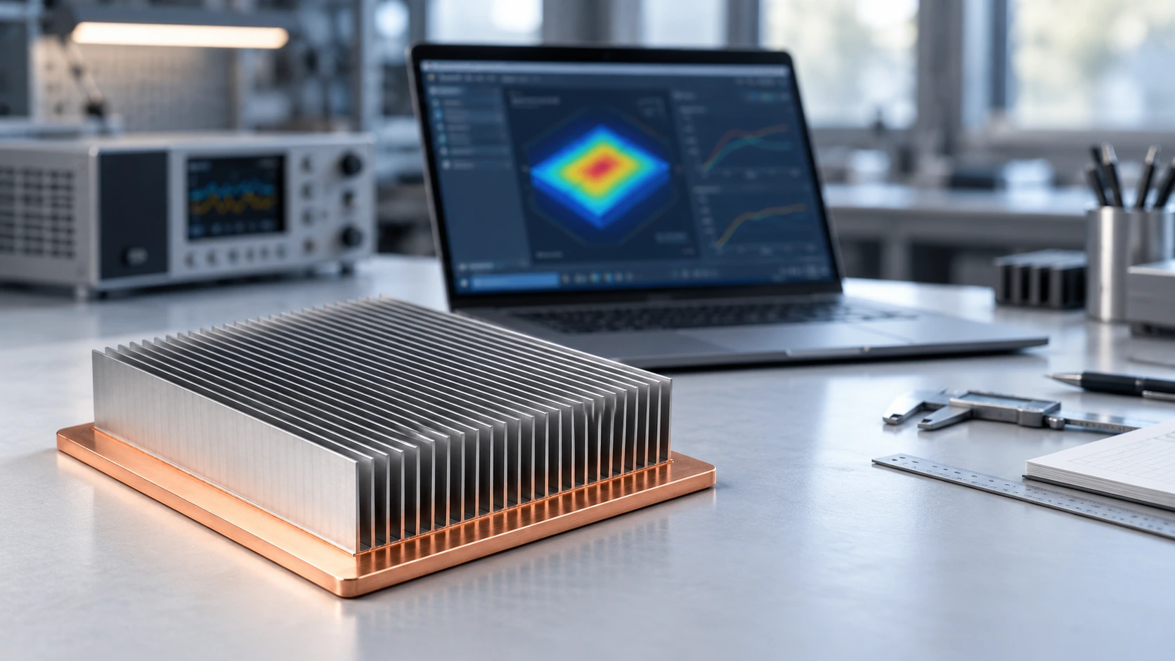
Let’s Build Your Vapor Chamber Cooling Solution
Share your heat source and installation constraints. We will help define the next engineering step.