
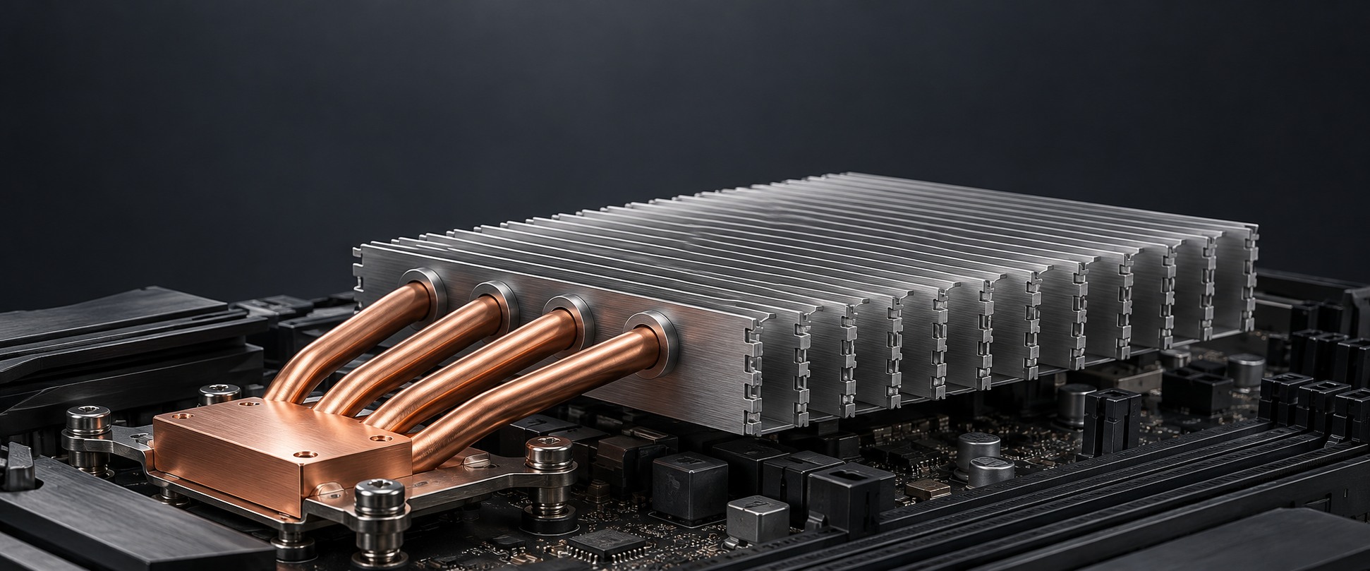
Custom Zipper Fin Heat Sinks for Compact Forced-Air Cooling
Turn limited enclosure space into an effective cooling surface. morton engineers interlocking aluminum or copper fin stacks with the heat-transfer interfaces, airflow paths, and mounting details your equipment needs.
- Controlled fin spacing
- Heat pipe and baseplate integration
- Prototype-to-production support
Share your thermal load, available space, and airflow requirements.
Request a Zipper Fin Design Review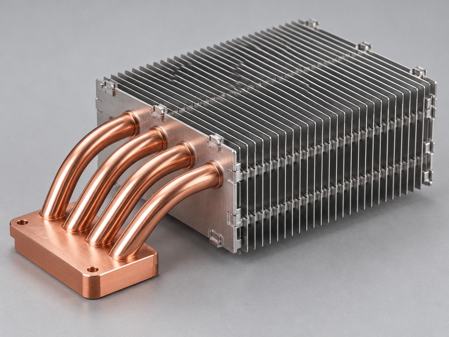
How Zipper Fin Heat Sinks Work
Individually stamped fins interlock into a stable stack. Their repeated channels expose a large metal surface to moving air, while a separately engineered connection transfers heat from the baseplate or heat pipes into the fins.
Interlocking stamped fins
Formed edge tabs locate adjacent plates and maintain the specified fin pitch.
A defined thermal interface
Pipe collars, soldered joints, brazed joints, or approved bonding methods create the required heat-transfer path.
An open path for cooling air
Aligned channels work with your duct and fan to carry heat out of the enclosure.
Start with a fin stack built around your system architecture.
Discuss Your Fin StackMore Cooling Surface in Your Available Space
Thin stamped fins and a configurable stack let you balance surface area, weight, airflow resistance, and assembly space around the needs of your equipment.
Use enclosure volume effectively
Thin plates create substantial wetted surface without the thick fin sections of many conventional profiles.
Keep channels consistent
Interlocking features maintain repeatable spacing to support predictable airflow and assembly checks.
Adapt the cooling footprint
Fin count, height, width, and cutouts follow the available envelope and nearby component clearances.
Support focused heat transport
Integrate the stack with heat pipes or a machined base to distribute heat beyond a small contact area.
Zipper Fin Design and Manufacturing Capabilities
Define the fin stack and its interfaces as one controlled assembly. The following manufacturing ranges help frame an initial engineering review.
| Typical envelope | 40–250 × 40–300 × 15–100 mm (L × W × H) |
| Fin construction | Interlocking stamped aluminum or copper plates |
| Thermal interfaces | Heat pipe collars, baseplate joints, and contact blocks |
| Mechanical features | Pipe openings, edge tabs, cutouts, brackets, and mounting interfaces |
| Surface condition | Bare metal or application-specific finish with interface masking |
| Design review | Fin pitch, plate thickness, stack height, joint method, and airflow assessed together |
Match Fin Pitch to Your System Airflow
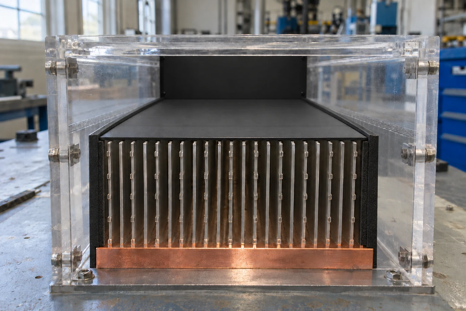
A denser stack adds area and resistance at the same time. We evaluate the fin channels with your fan curve and duct geometry to establish an achievable operating point.
Use installed airflow
Specify the air passing through the effective fin area, rather than the fan's free-air rating.
Review pressure drop
Balance pitch, channel length, inlet conditions, and bypass control against available fan pressure.
Preserve a clean air path
Align fins with the intended flow and account for filters, cable obstructions, and dust exposure.
Connect Your Heat Source to the Full Fin Stack
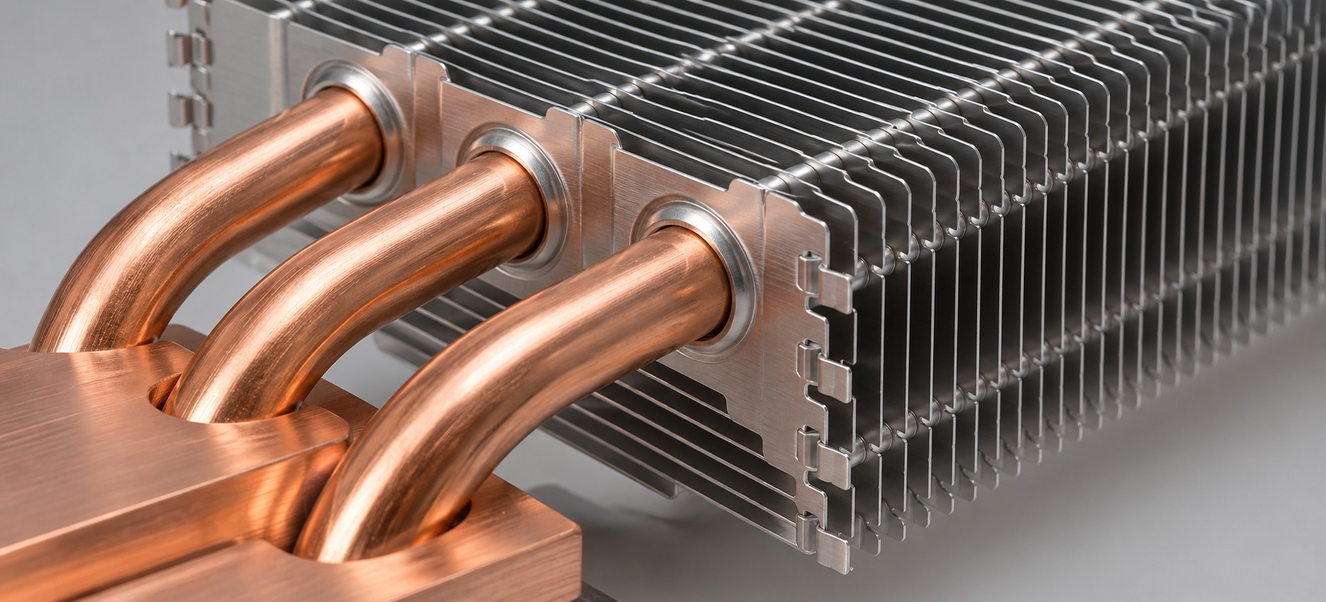
Fin spacing alone does not establish a thermal joint. We engineer the contact block, heat pipes or baseplate, and fin connection to form a continuous path from your device to the cooling air.
Capture heat at the interface
Match the contact footprint, flatness, TIM, and clamping load to the device and mounting limits.
Spread heat to the cooling area
Select a baseplate or heat pipe arrangement for the source position, distance, and installation orientation.
Control the fin connection
Specify the joint method, contact fit, and inspection criteria for the selected material combination.
Materials and Finishes Matched to Your Application
Choose the fin and base materials around heat spreading, weight, joining compatibility, and the environment your equipment will operate in.
Aluminum fin stacks
A practical choice when low mass, airflow surface area, and assembly cost are central design goals.
- Lightweight stamped construction
- Compatible joint method defined during DFM
- Surface protection reviewed for the environment
Copper fin stacks
A useful option when local conduction or a copper thermal architecture justifies the additional mass.
- High thermal conductivity
- Mass and mechanical support reviewed
- Material and joint specifications controlled together
Heat-contact areas and joining surfaces are masked or finished to the approved drawing. Coatings are selected for their purpose and are not assumed to improve every cooling condition.
Compare material and finishing options against your actual requirements.
Select Materials with Our EngineersCustom Geometry for a Better Mechanical Fit
Build the fin stack around your enclosure, component clearances, and assembly sequence so cooling hardware fits the equipment it serves.
Envelope and fin geometry
Define stack length, width, height, fin count, pitch, and local cutouts.
Heat-source alignment
Position contact blocks and pipe routes around the approved heat-source layout.
Mounting and load control
Review bracket datums, fasteners, TIM compression, and allowable device loading.
Assembly and service access
Protect connector clearance, tool access, cable paths, and fin edges during installation.
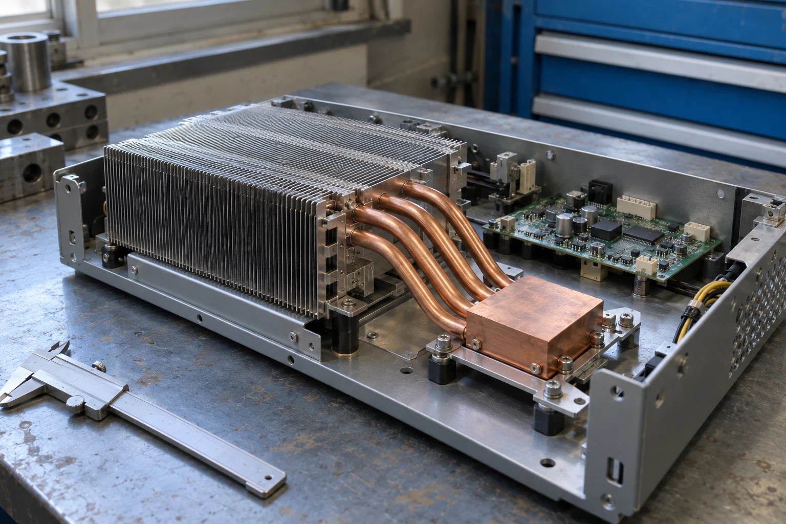
Share a 3D model to uncover fit and assembly risks early.
Request a Mechanical Fit ReviewZipper Fin Cooling for Space-Constrained Electronics
Configurable fin stacks support equipment that combines concentrated heat sources with a controlled forced-air path and limited internal space.

Industrial and edge computing
Align a compact fin-and-heat-pipe assembly with processor locations, board clearances, and chassis airflow.
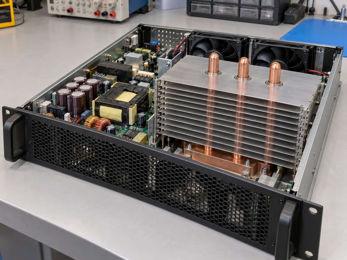
Telecom power equipment
Move heat from concentrated power stages into a fin area that works with the existing fan and duct.
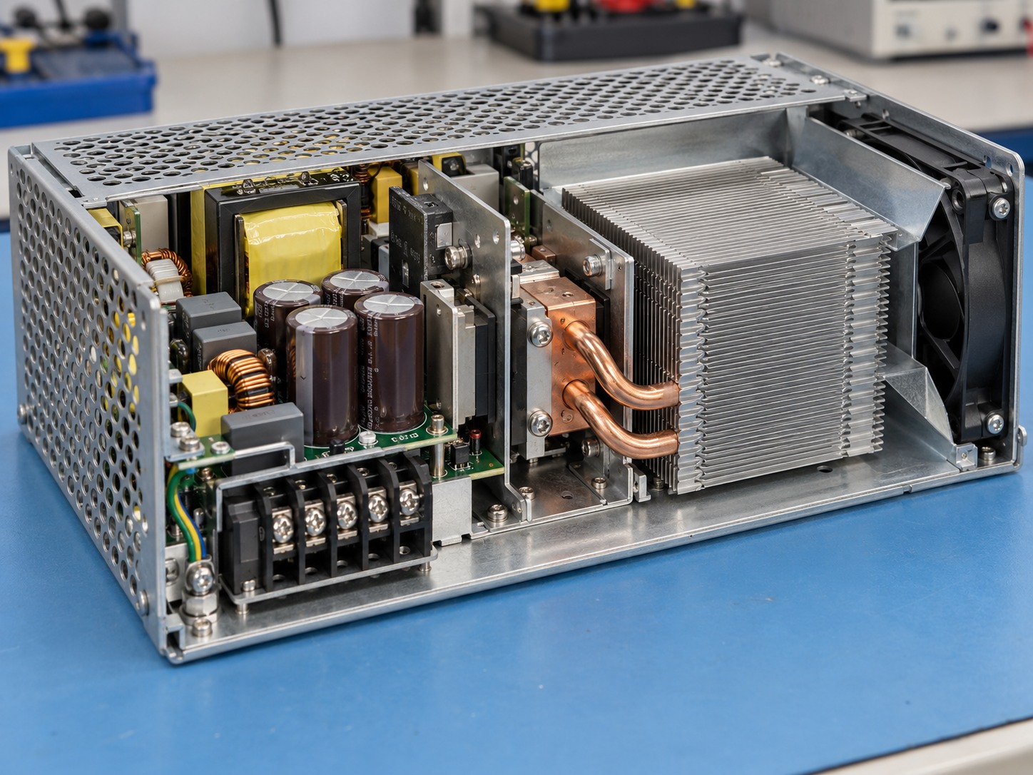
Compact industrial power supplies
Balance cooling surface, electrical clearances, mounting interfaces, and repeatable assembly.
Tell us where the assembly will operate and what limits the cooling design.
Review Your ApplicationThermal Performance Verified Under Defined Conditions
Turn a cooling concept into a repeatable test. Simulation and sample measurements use documented boundary conditions so your team can compare results on the same basis.
Define the boundaries
Record effective heat load, source size, inlet temperature, mounting orientation, TIM, and clamping condition.
Evaluate the design
Use thermal networks and CFD to assess heat spreading, fin temperatures, flow distribution, and pressure loss.
Correlate with hardware
Measure stabilized temperatures, installed airflow, and air pressure drop on the approved sample setup.
Agree on the test setup before comparing cooling performance.
Define Your Validation Plan450 W Telecom Power Supply Cooling Case
For a Singapore telecom power supply project, morton combined aluminum zipper fins, eight 8 mm copper-water heat pipes, and a copper contact block to handle an offset heat source within an 80 mm height limit.
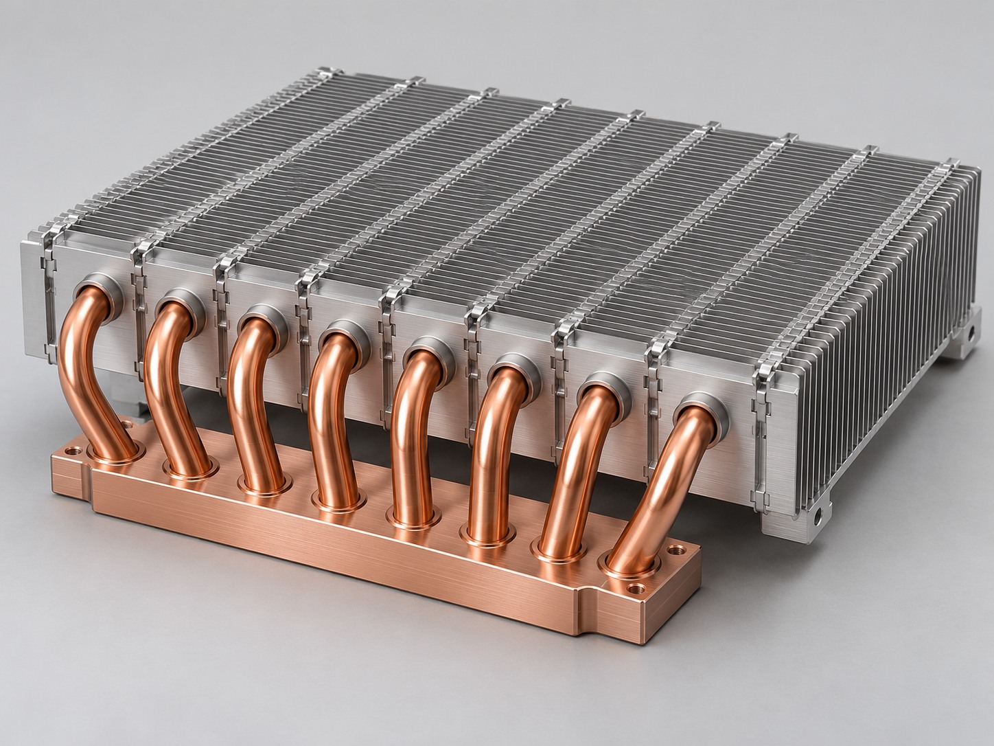
Defined operating conditions
200 × 250 × 80 mm envelope; 60 × 60 mm source; 25 °C inlet air; 220 m³/h installed airflow; design mounting orientation.
An integrated thermal path
Pipe condenser coverage and fin spacing were adjusted to distribute heat while retaining the equipment's existing fan.
Validated for project release
Samples completed the specified vibration and −20 to 80 °C thermal-cycle screening. Sample-to-approval time was seven weeks.
Use your own boundary conditions to evaluate a comparable assembly.
Discuss a Similar Cooling ChallengeRepeatable Fin Assembly and Controlled Quality
Translate the approved design into material requirements, assembly controls, inspection records, and protective packaging for repeat orders.
Material and drawing control
Link material batches and work orders to the approved drawing, BOM, and process revision.
Fin and stack inspection
Check fin pitch, stack dimensions, edge condition, locking features, and specified joint characteristics.
Assembly verification
Verify critical contact dimensions and sample thermal performance under the agreed test conditions.
Traceable shipment
Supply agreed FAI and inspection records, batch identification, and packaging that protects thin fins.
- 1 Material verification
- →
- 2 Stamping and forming
- →
- 3 Stack assembly
- →
- 4 Joint inspection
- →
- 5 Release and packaging
Make your critical characteristics part of the production control plan.
Review Quality and DocumentationFrom Engineering Samples to Repeat Production
Work with one project team through requirements, DFM, sample verification, and controlled production release.
Requirements and DFM
Review drawings, thermal boundaries, joint strategy, annual demand, and inspection needs.
Prototype planning
Define sample quantity, tooling, cost, and schedule. Paid engineering samples can start from one piece.
Validation and approval
Confirm fit, temperature, airflow, connection reliability, and the approved drawing revision.
Production and delivery
Freeze the BOM and control plan, then coordinate batch inspection, protective packing, and shipment.
Useful RFQ inputs: 2D/3D files, heat load and source size, target temperature, airflow or fan curve, available envelope, mounting orientation, and expected annual demand.
Send the information you have; our engineers will help close the remaining gaps.
Start Your Zipper Fin RFQZipper Fin Heat Sink FAQs
Get practical answers about fin construction, airflow, integration, and the information needed for a custom project.
How are zipper fins different from folded fins?
Zipper stacks use individual stamped plates with interlocking features. Folded fins are formed from a continuous strip. The suitable structure depends on the airflow, joint method, geometry, and assembly needs.
Do interlocking tabs provide the thermal connection?
The tabs primarily locate the fins and control pitch. Heat transfer from a pipe or baseplate depends on a separately specified interface and joining process.
Can zipper fins be used with natural convection?
The dense channels common in zipper stacks are usually developed for forced airflow. Natural-convection use requires a separate review of pitch, orientation, and available temperature rise.
Can you integrate heat pipes and mounting hardware?
Yes. The fin stack, heat pipes or baseplate, contact block, brackets, fasteners, and TIM can be reviewed as an assembly against the approved design.
What determines thermal capacity?
Capacity depends on source size, temperature limits, airflow and pressure drop, joint quality, fin geometry, and orientation. A wattage rating without those conditions does not define the assembly's performance.
What should I send for a quotation?
Send available drawings, heat load, source footprint, temperature limits, enclosure space, airflow information, orientation, sample quantity, and annual demand. We can clarify missing information during engineering review.
Have a requirement that needs an engineering answer?
Ask a Zipper Fin Engineer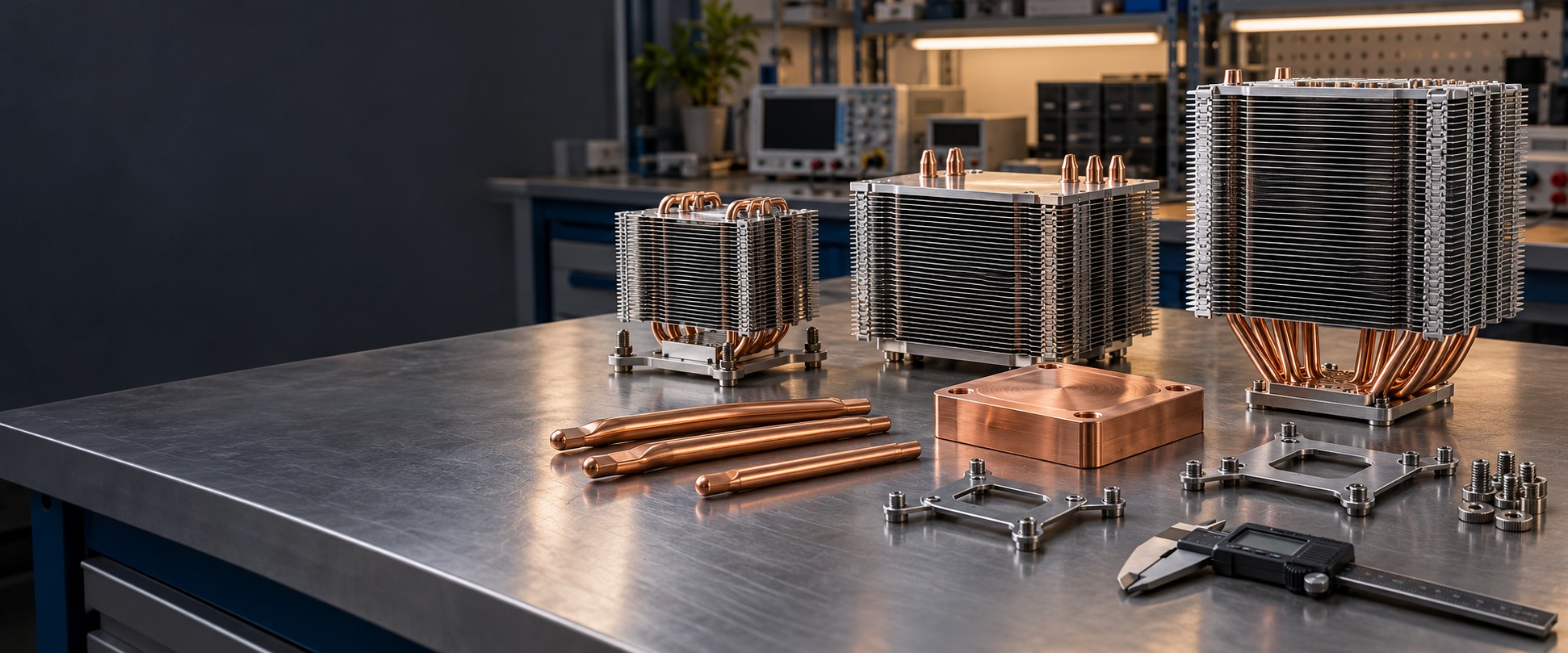
Discuss Your Zipper Fin Heat Sink Project
Share your cooling challenge with morton. We will review the thermal boundaries, available space, and manufacturing requirements for a practical next step.
Application-focused design
Fin pitch, heat transport, and mounting reviewed together.
Engineering collaboration
DFM, simulation, and sample validation under defined conditions.
Controlled production
Approved drawings, inspection records, and batch traceability.
Flexible project support
From paid engineering samples to scheduled repeat orders.
Request an Engineering Review
Tell us what you are building and where cooling is constrained.