
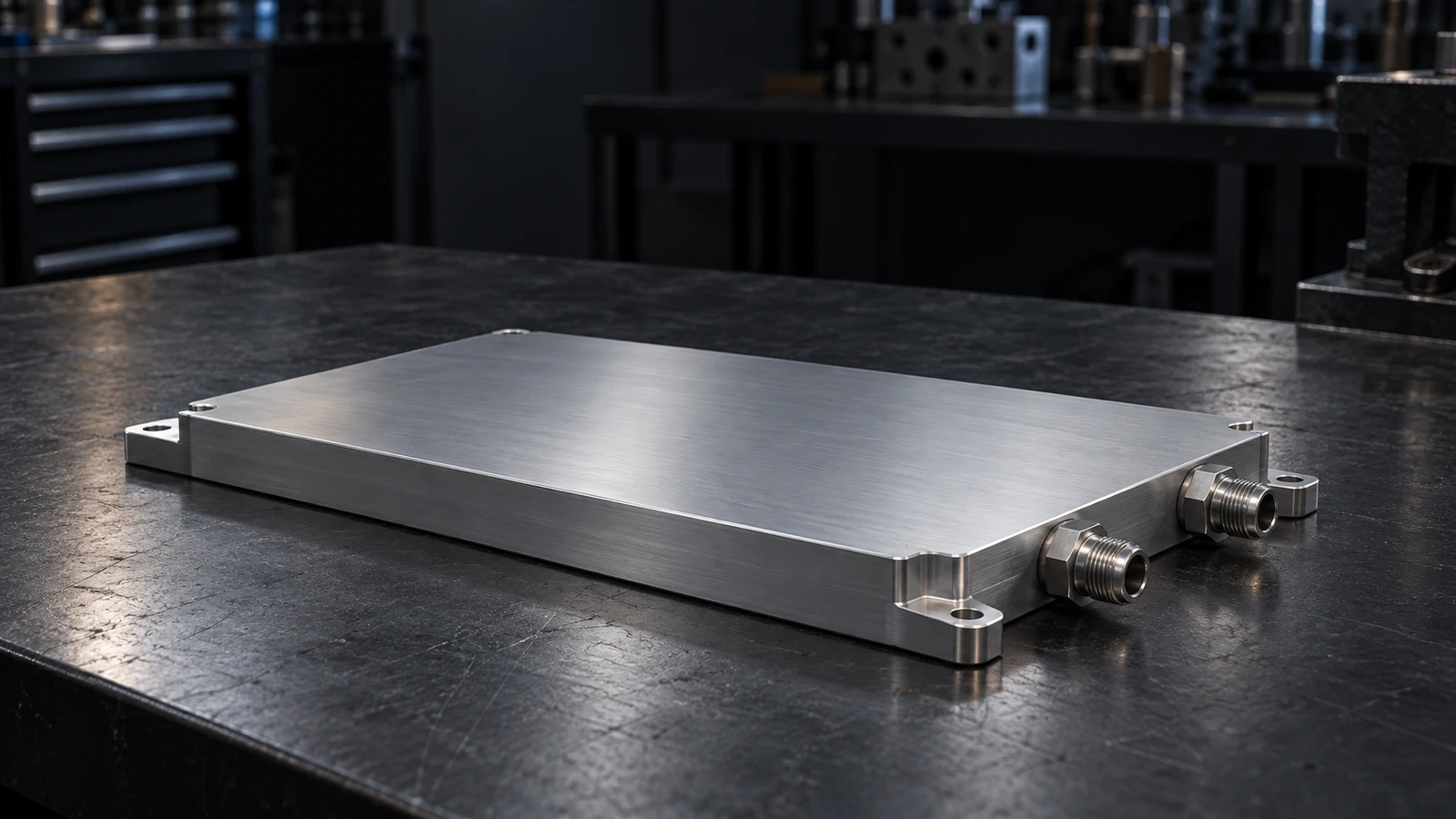
Vacuum Brazed Cold Plates
Custom aluminum cold plates that bring complex internal cooling paths into one compact, sealed assembly—for power electronics built to run reliably.
Brazed internal fins
More wetted surface where your heat sources need it.
Engineered flow paths
Thermal performance balanced with available pump pressure.
Verified assemblies
Pressure, leak and interface checks tied to your drawing.
Turn your thermal requirements into a manufacturable cold plate.
Discuss Your Cold Plate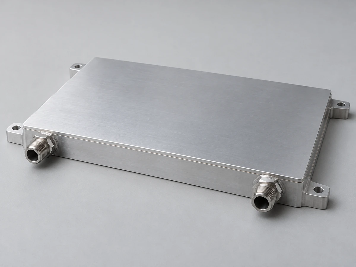
One Sealed Assembly. A Defined Thermal Path
A vacuum brazed cold plate joins a machined body, internal fins or channels, and a cover using a compatible braze alloy. Heat travels from your mounting surface into the circulating coolant.
Precision contact surface
A controlled interface helps reduce gaps between the module, TIM and plate.
Brazed internal structure
Fins and channels increase wetted area within a compact envelope.
Integrated coolant cavity
A permanently joined enclosure supports application-specific port and mounting layouts.
Share your heat-source layout to define the right internal structure.
Review My ApplicationBuilt Around Your Power Electronics
Connect the cold plate’s construction to the needs of your module, coolant loop and production line.
Targeted heat transfer
Place internal surface area beneath demanding heat-source zones.
Compact packaging
Combine the coolant cavity and thermal interface in one low-profile part.
Controlled flow distribution
Guide coolant across multiple modules while managing bypass paths.
Balanced pressure drop
Match the internal passage design to the pump operating point.
Defined mounting interfaces
Coordinate ports, fasteners and contact surfaces with the equipment envelope.
Repeatable production
Carry approved materials, process controls and inspections into each batch.
Tell us which thermal, hydraulic or packaging constraint matters most.
Set My Design PrioritiesA Practical Starting Point for Your Specification
Define the envelope and operating conditions together so the geometry, joints and interfaces can be assessed as one design.
Send your 2D drawing or STEP model for a manufacturability review.
Discuss My SpecificationEngineer the Flow Inside the Plate
Fin geometry, distribution spaces and channel connections determine how coolant reaches each heat source—and how much pressure the plate requires.
Distribute before exchanging
Size inlet and outlet distribution spaces to feed the active cooling area.
Place fins with a purpose
Select fin height, spacing and orientation for heat transfer, pressure drop and cleanliness.
Protect the joining surfaces
Keep braze lands, fit-up and fixtures compatible with the selected material system.
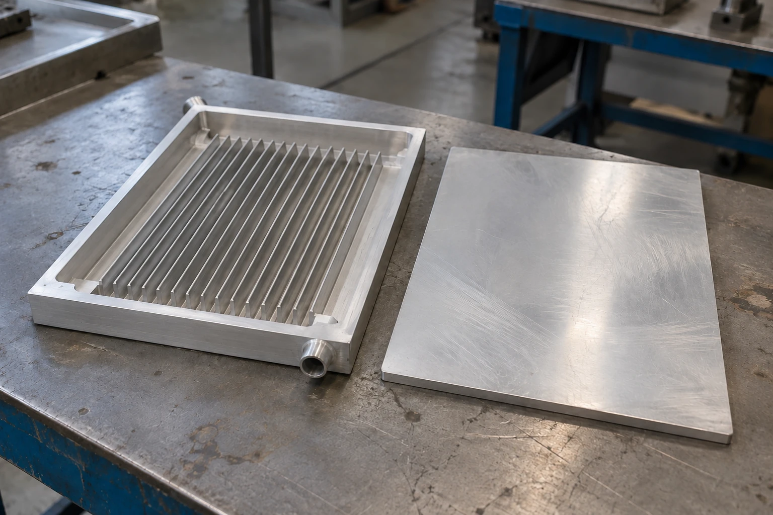
Map your heat-source positions to a tailored flow-path concept.
Explore My Flow LayoutBalance Temperature Margin with Pump Demand
A useful thermal result belongs to a defined test condition. We assess temperature rise and plate pressure drop together.
Thermal inputs
Continuous and peak heat load, source footprint, target temperature and TIM.
Hydraulic inputs
Coolant formulation, inlet temperature, flow range and available pump pressure.
Mechanical inputs
Envelope, mounting load, contact flatness, port clearance and allowable mass.
Measured between the plate inlet and outlet, excluding external hoses, filters and pump.
Record heat-source arrangement, sensor locations, coolant properties and steady-state criteria.
Share your operating boundaries for a relevant thermal and hydraulic assessment.
Define My Test ConditionsChoose Materials for the Complete Cooling Loop
The alloy, braze cycle, surface condition and coolant chemistry must work together throughout the equipment’s operating life.
Material and braze compatibility
Review 3003 or 6061 with the selected filler, joint clearance and furnace cycle.
Post-braze condition
Evaluate strength, distortion and any approved heat-treatment sequence after joining.
Coolant compatibility
Use an inhibited coolant verified for all wetted materials in the loop.
Operating conditions
Confirm temperature, pressure, freeze protection and maintenance intervals together.
Surface treatment
Specify masking for contact, sealing, grounding and threaded surfaces.
Corrosion management
Assess dissimilar metals, water quality and coolant chemistry before release.
Bring your coolant specification and material requirements into the design review.
Check Material CompatibilityFrom Prepared Components to a Controlled Assembly
A repeatable cold plate depends on more than the furnace cycle. Control starts with materials and continues through final machining and inspection.
Material verification
Confirm alloy, filler and batch documentation against the released specification.
Machining and preparation
Produce the cavity and interfaces; remove contamination before assembly.
Fit-up and fixturing
Position the internal core and cover with controlled joint clearances.
Vacuum brazing
Use qualified specialist suppliers under approved material, process and inspection requirements.
Final machining
Establish the specified contact surface, ports and mounting features.
Clean, test and release
Complete pressure, leak, dimensional and document checks before packing.
Review the manufacturing route before committing your design to production.
Request a Process ReviewVerify the Interfaces You Depend On
Each industrial cold plate follows a defined release plan, with pressure and leakage checks linked to the approved design.
Hydrostatic proof test
For the 0.3 MPa rated design: 0.6 MPa gauge pressure for 10 minutes, with no leakage or permanent deformation.
Final gas-tightness check
Dry air or nitrogen at 0.3 MPa; stabilized test with a typical acceptance limit of ≤0.05 sccm equivalent air.
Dimensional verification
Check contact surfaces, port threads and critical mounting features to the drawing.
Align your acceptance criteria with the cold plate’s release plan.
Discuss My Validation PlanCooling Where Electrical Power Is Converted
Vacuum brazed cold plates support compact power-conversion assemblies when the thermal interface and coolant loop are designed together.
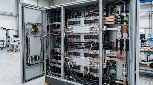
Industrial Drives & Inverters
Coordinate IGBT or SiC module footprints, mounting loads and coolant distribution.
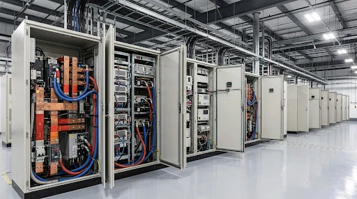
Energy Storage PCS
Manage multi-module losses with defined inlet conditions and project-level validation.
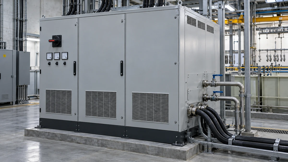
Rectifiers & Power Supplies
Integrate flat contact surfaces and serviceable fluid connections into dense equipment.
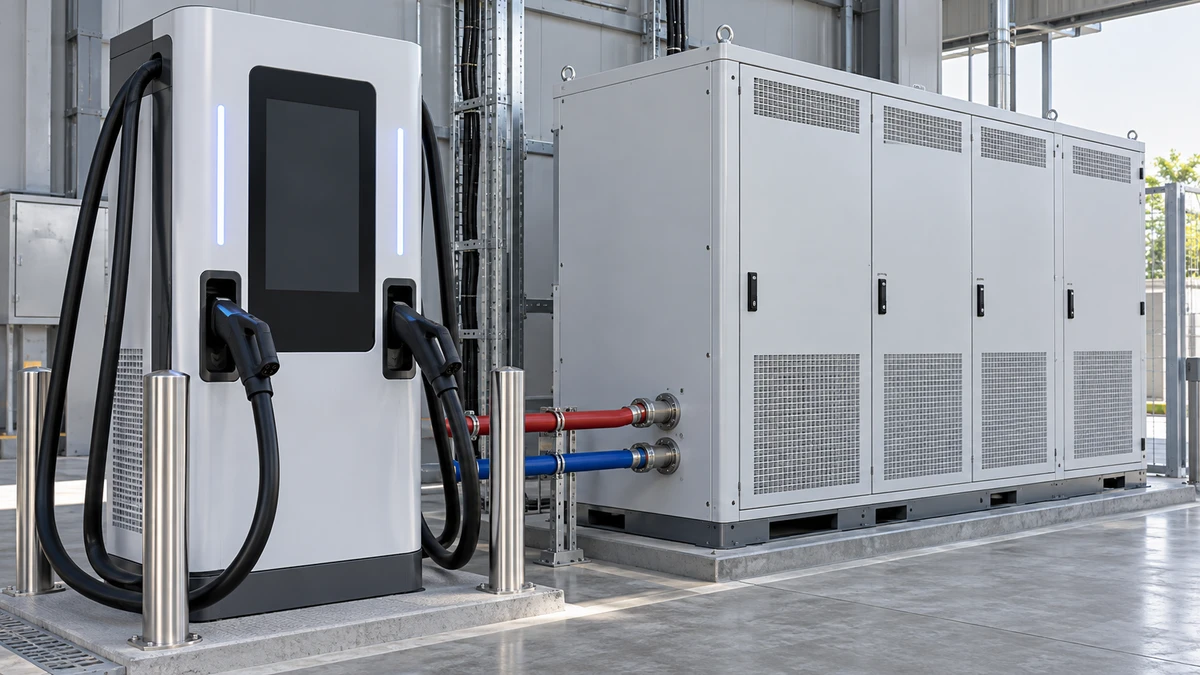
EV Charging Power Modules
Develop compact cooling interfaces for repeatable power-module assembly.
Describe your equipment platform and the heat sources it needs to cool.
Discuss My ApplicationA Clear Route from Requirements to a Tested Sample
Start with the thermal boundary and finish with an approved design package that production can follow.
Your design inputs
Required ScopeInput & Feasibility Assessment
Clarify missing inputs and assess the material, flow-path and interface requirements.
DFM & Simulation Engineering
Develop the geometry, DFM recommendations and agreed simulation scope.
Precision Tooling & Brazing
Build engineering samples against controlled drawings and test requirements.
Test Comparison & Sign-Off
Compare thermal, hydraulic and mechanical results; close changes before approval.
Start with a drawing—or a clear set of thermal and space constraints.
Start My Engineering ReviewCarry the Approved Design into Every Batch
Give engineering, purchasing and quality teams a shared reference for ordering, inspection and repeat supply.
Controlled product definition
Approved 2D/3D drawings, BOM, material specification and process revision.
Inspection and traceability
FAI, material batch records, critical dimensional checks and pressure/leak records.
Managed changes and delivery
Customer-approved changes, agreed packing, part identification and phased supply.
FAI report
Critical dimensions and interfaces.
Material records
Batch-linked verification.
Test records
Pressure and leakage release.
CoC & packing
Agreed shipment documentation.
Tell us which quality documents your supplier approval process requires.
Build My Documentation PackageOne Team for Engineering, Quality and Supply
morton connects cold plate design, controlled specialist joining and final verification through one accountable project team.
9 engineering specialists
Thermal, mechanical, process and test expertise support your project review.
1-piece sample entry
Paid engineering samples can begin from one unit, with scope agreed by project.
20–50-piece production MOQ
Typical liquid cold plate production entry, depending on complexity and tooling.
4–8-week development cycle
Typical first-round joint development and testing, starting from agreed requirements.
Plan a sample and supply route that fits your project stage.
Discuss My Project ScheduleQuestions Before You Specify a Brazed Cold Plate
Resolve the details that affect manufacturability, operating reliability and procurement.
Can you build to our drawing?
Yes. Share your 2D drawing, 3D model and operating requirements. We review manufacturability, materials, interfaces and test criteria before quotation.
Is 6061-T6 strength retained after brazing?
The brazing thermal cycle changes the material condition. We assess the post-braze properties and any approved heat-treatment sequence against the design loads.
Which coolant should we use?
Select an inhibited fluid compatible with the full wetted loop. Provide its formulation, concentration, temperature range and maintenance requirements for review.
Do you test every cold plate for leakage?
Industrial cold plates receive individual proof and final gas-tightness checks under a defined release plan. Acceptance limits and any additional validation follow the approved specification.
What is needed for a meaningful thermal result?
Heat load, source footprint, inlet coolant temperature, formulation, flow, mounting interface and sensor positions must be defined. Plate pressure drop is recorded separately.
Can we start with samples before production?
Paid engineering samples can start from one unit. Sample timing and the economic production quantity depend on the design, tooling and validation scope.
Have a requirement that needs a direct engineering answer?
Ask About My Cold Plate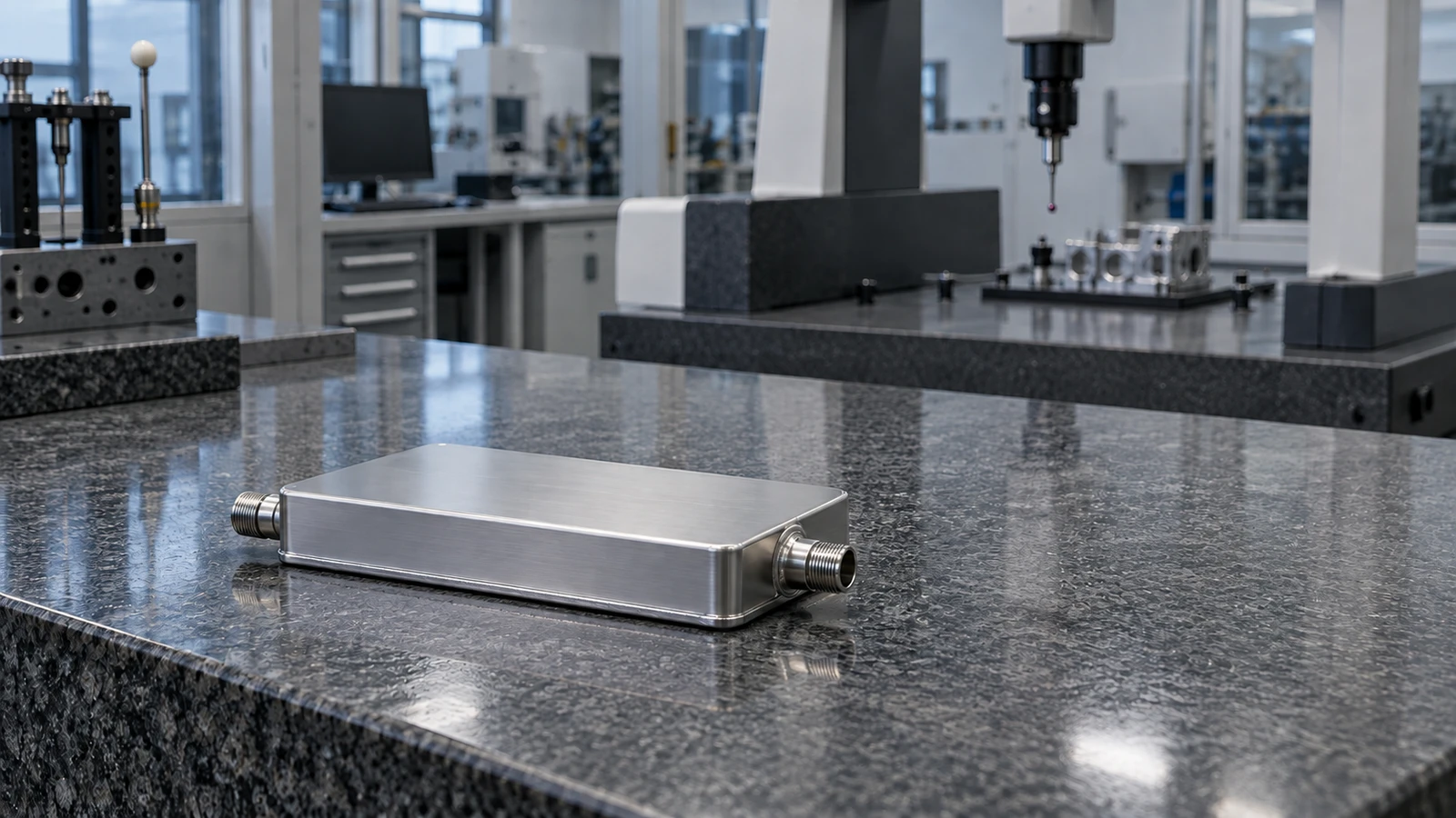
Let’s Define Your Next Cold Plate
Share your thermal targets, available space and coolant conditions. Our team will help you define the next engineering step.