
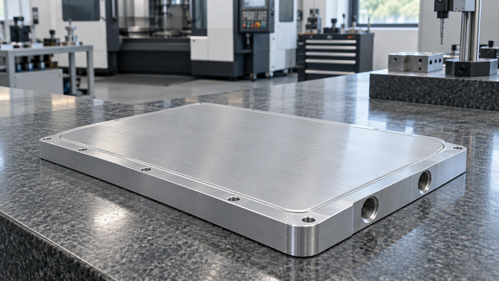
Friction Stir Welded Cold Plates
Custom aluminum cold plates engineered around your heat sources, coolant circuit and production requirements.
Bring your thermal, mechanical and quality requirements into one engineering review.
Discuss Your Cold Plate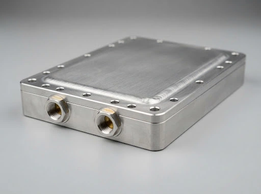
An Aluminum Cooling Circuit Built Around Your Assembly
A machined aluminum base carries the coolant channels. A compatible cover is joined by friction stir welding to create the enclosed cooling circuit.
Start with your assembly envelope and heat-source layout.
Review Your DrawingWhy Choose a Friction Stir Welded Structure?
Solid-state joining gives aluminum cold plates a practical route to sealed channels, controlled interfaces and repeatable manufacturing.

No filler metal
The base and cover are joined without brazing filler, simplifying material selection within the approved aluminum system.

Designed weld continuity
A defined tool path and supported weld lands help form a consistent sealing boundary.

Flexible channel placement
CNC-machined flow paths can follow multiple heat sources and installation constraints.

Production-focused control
Welding, finish machining and inspection are tied to a released process and part revision.
Put the Flow Path Where the Heat Is
Channel layout, cover thickness and weld support are developed together so thermal performance does not come at the expense of structural integrity.
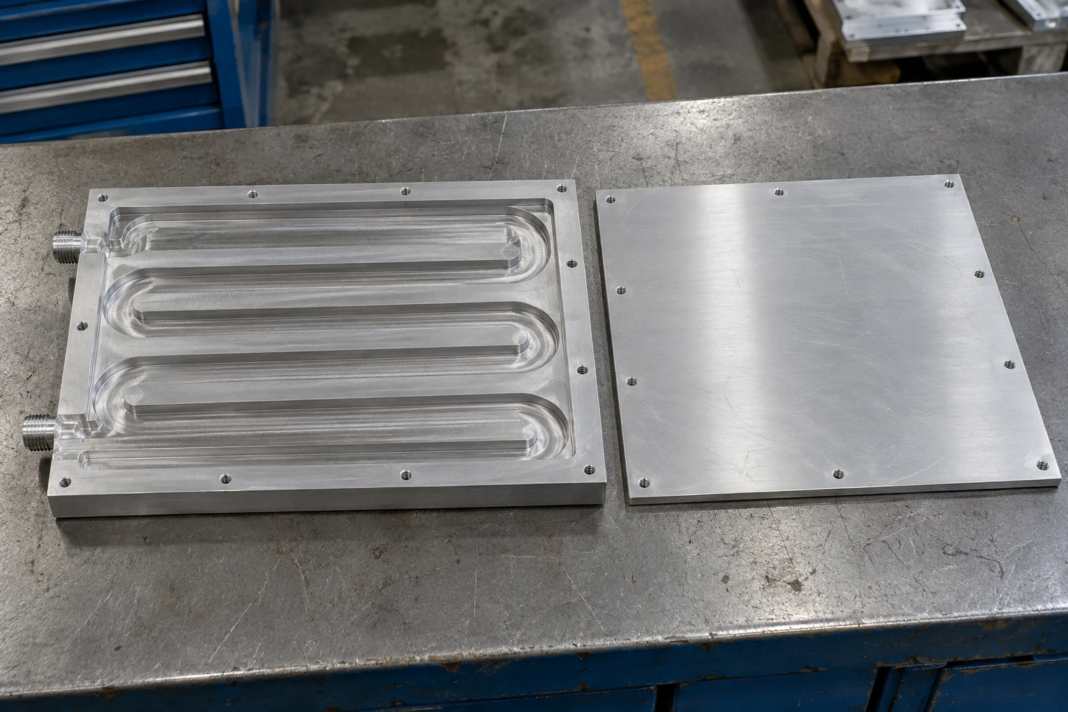
Heat-source coverage
Route flow beneath the loaded areas and review temperature distribution across the mounting face.
Supported weld lands
Retain sufficient solid material beneath the tool path and assess the load on the cover.
Controlled flow distribution
Review turns, inlet distribution and purge paths to limit unnecessary pressure loss and trapped air.
A Practical Starting Range for Custom Designs
Select the material, envelope and interface finish as one design package. Final dimensions are reviewed against the channel and welding requirements.
 Design & Manufacturing Baseline Specifications
Send the drawing tolerances that matter to your assembly.
Confirm Manufacturing FitBalance Temperature, Flow and Pump Demand
Cold plate performance is evaluated at your heat load, coolant and inlet temperature, with pressure drop measured across the plate itself.
Define the load
Provide continuous and peak power, source dimensions, positions and allowable mounting-face temperature.
Define the circuit
Specify coolant formulation, inlet temperature, available flow and the plate pressure-drop budget.
Verify the operating point
Use thermal testing and flow measurements to confirm the design under the agreed boundary conditions.
What your validation report records
Report Data What your validation report records
- Heat-source layout and sensor positions
- Base hotspot and coolant inlet temperatures
- Coolant flow, formulation and plate pressure drop
- Mounting method, TIM and steady-state criteria
Turn your operating conditions into a testable cold plate specification.
Define Your Test ConditionsMake the Cold Plate Fit the Whole Assembly
Mechanical details are resolved alongside thermal design so the approved plate is straightforward to install and reproduce.

Thermal contact faces
Define flatness, surface finish and local machining datums around the actual device footprint and TIM.

Coolant connections
Position ports for hose clearance, tool access and sealing, with thread type and sealing method stated on the drawing.

Mounting and protection
Review screw loads, engagement, electrical clearances and masking of contact or grounding surfaces.
Resolve port, fastening and contact-face details before sampling.
Review Assembly InterfacesControl the Joint Before You Inspect the Plate
A released welding route connects material selection, joint geometry, fixturing and inspection into a repeatable manufacturing process.
1 Material and joint review
Confirm aluminum compatibility, cover fit, weld-land width and backing support.
2 Qualified process route
Define tooling, clamping and process parameters with an approved specialist welding partner.
3 Weld and distortion control
Manage seam continuity, cover deformation and tool entry or exit features within the released design.
4 Finish and verify
Machine contact surfaces and inspect critical dimensions after welding to capture the final condition.
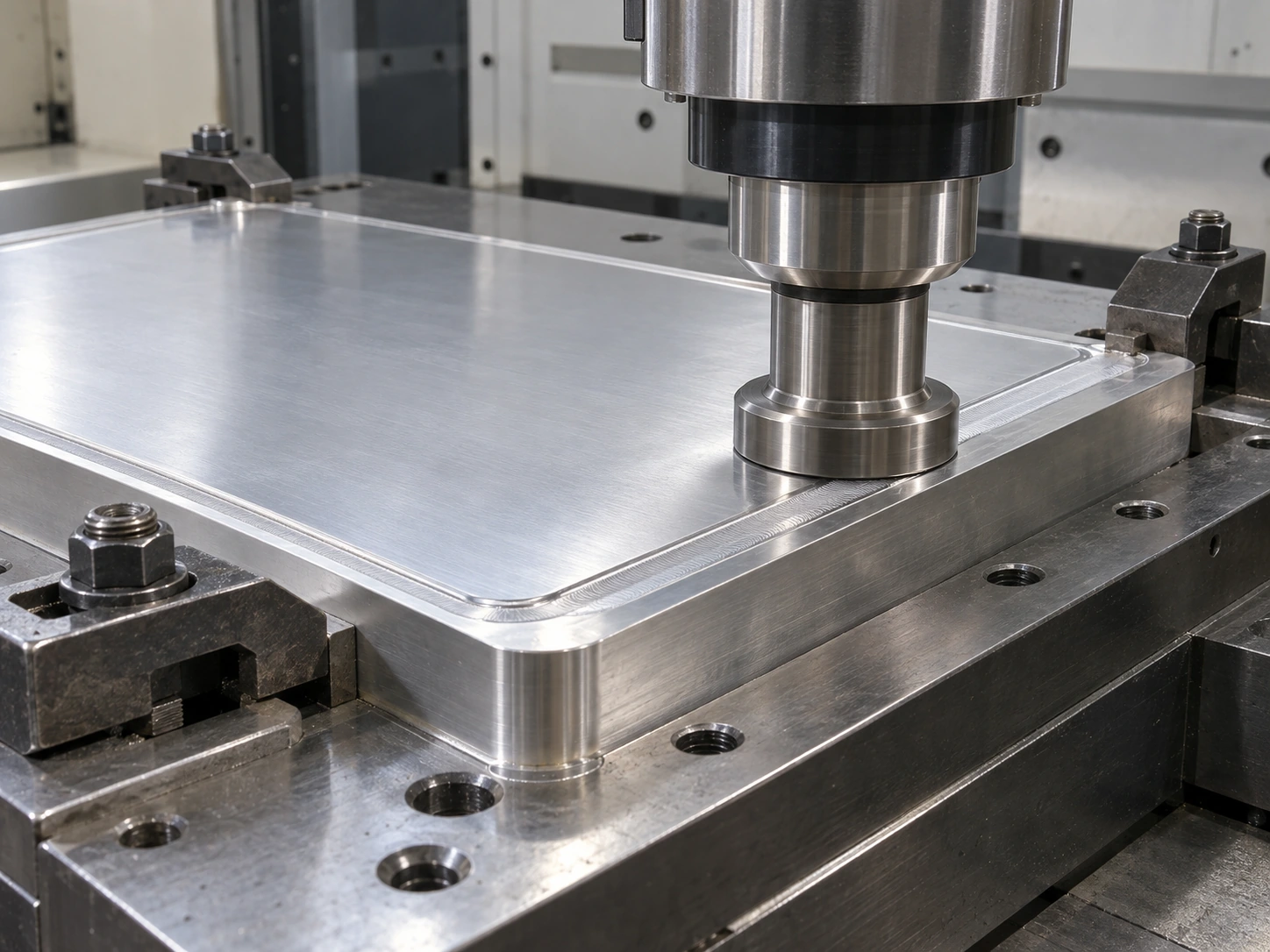
Link the weld specification to your finished-part acceptance criteria.
Discuss Weld ControlsEvery Plate Follows a Defined Leak-Test Route
For the standard 0.3 MPa rated design, proof testing and final gas leak testing are linked to the part and inspection record.
Hydrostatic proof
0.6 MPa for 10 minutes, with no leakage or permanent deformation.
Drain, clean and dry
Remove test liquid and control residual moisture and channel contamination.
Final gas leak test
0.3 MPa dry air or nitrogen; 60–120 seconds stabilization followed by 120 seconds testing.
Record and release
Standard limit ≤0.05 sccm equivalent air, referenced to 20 °C and 101.325 kPa; link results to the production record.
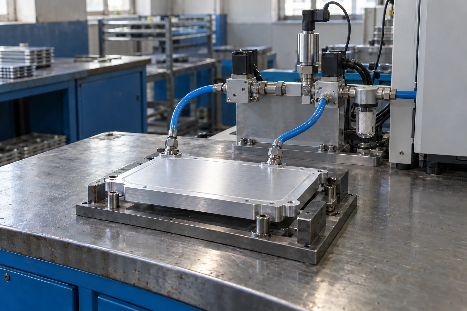
Build your leak and proof requirements into the control plan.
Align Your Quality RequirementsDesign for the Coolant That Will Actually Run
The cold plate, fittings and operating fluid are reviewed as a material system to support stable long-term service.

Inhibited coolant
Use a formulation validated for the wetted materials. Common water/glycol mixtures contain 20–40% glycol by volume.

Operating temperature
A typical inlet range is 15–60 °C, with dew point, freezing margin and start-up viscosity reviewed for the installation.

Water quality and corrosion
Control pH, conductivity and chloride content to the coolant specification, and assess mixed-metal compatibility.

Cleanliness and maintenance
Define filtration, flushing, venting and fluid replacement around the minimum channel size and system requirements.
Share the intended fluid and service conditions before design freeze.
Review Coolant CompatibilityBuilt for Industrial Power Electronics
Friction stir welded cold plates suit aluminum liquid-cooling assemblies where heat-source layout, sealed channels and production control must work together.
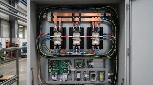 Power Inverters
Industrial drives and inverters
Cool IGBT or SiC power stages while fitting the mounting pattern, busbar clearance and coolant connections.
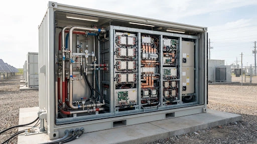 Utility Storage
Energy storage PCS
Support repeatable power-module cooling with a defined coolant specification, pressure boundary and service interface.
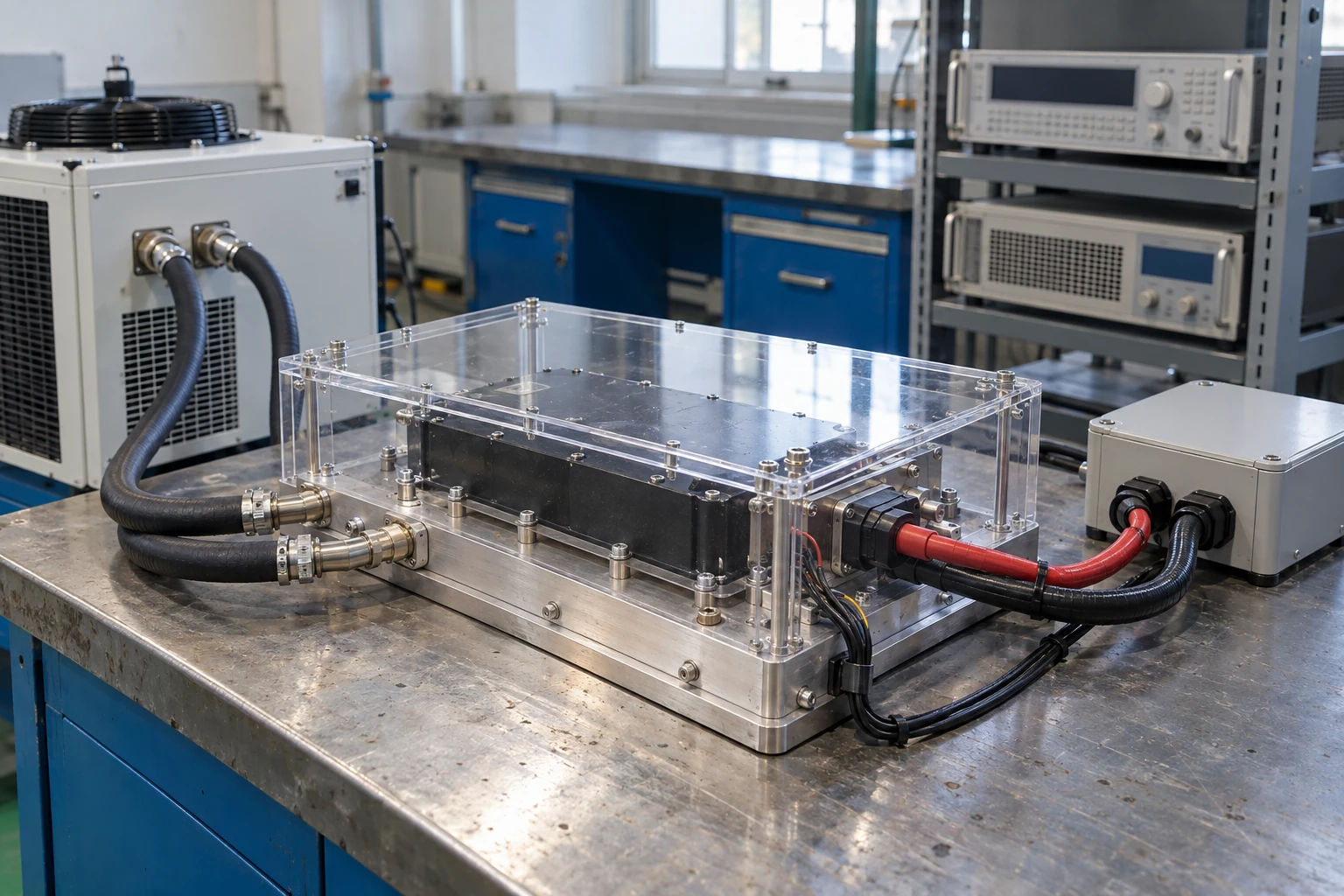 Test Instrumentation
Power test equipment
Handle concentrated main heat loads and coordinate the liquid-cooled zone with the surrounding test assembly.
Match the plate to the duty cycle and constraints of your equipment.
Discuss Your ApplicationAn FSW Cold Plate Inside a Power-Test Cooling Assembly
For a Netherlands power-test equipment project, the FSW liquid-cooled base managed the main heat source while separate fins and heat pipes handled auxiliary loads.
2.0 kW main load over 100 × 100 mm, plus 150 W auxiliary load; inlet water 30 °C at 8 L/min.

Approximately 64 °C with both main and auxiliary loads operating.
Approximately 0.017 K/W, based on the 2.0 kW main heat source and coolant inlet temperature.
Approximately 28 kPa across the cold plate at the stated water flow.
Primary heat dissipated across 100 × 100 mm direct base footprint.
Define comparable test boundaries for your own assembly.
Plan a Comparable ValidationMove from Drawing Review to Repeatable Supply
One project team coordinates engineering, qualified process partners, inspection and delivery against a controlled part revision.
Review and DFM
Confirm heat load, envelope, material, channel layout, interfaces and acceptance criteria.
Sample and validate
Build engineering samples and verify dimensional, thermal, hydraulic and sealing requirements.
Approve the production route
Freeze the drawing, first-article report, control plan and approved sample before volume release.
Supply and trace
Deliver batch-linked material records, inspection reports, leak-test results and part identification.
Share your target dates and annual demand to shape a realistic introduction plan.
Plan Samples and SupplyQuestions Before You Start a Cold Plate Project
Clarify the design inputs, manufacturing route and validation scope before requesting samples.
How is friction stir welding different from brazing?

FSW joins aluminum using a rotating tool in the solid state, without brazing filler. The joint geometry, fixturing and process qualification differ from a furnace-brazed design.
Can you make the plate from our drawing?
Yes. We review your 2D drawing and STEP model for channels, weld support, cover thickness, ports, contact faces and inspection access before confirming the route.
Which aluminum materials are available?
6061 and 6063 are common starting options. The alloy, temper and final mechanical requirements are selected together with the welding and finish-machining process.
What pressure and leak requirements can be specified?
The standard industrial design is rated at 0.3 MPa gauge pressure with a defined proof and gas leak-test route. Other ratings and tighter leak criteria require an approved design and validation plan.
Can the cold plate run with water/glycol?
Yes, when an inhibited formulation is validated for every wetted material. Specify glycol type, concentration, operating temperatures and water-quality limits so flow and pressure drop can be evaluated correctly.
What do you need for a useful quotation?
Send the drawing or available envelope, heat-source layout and power, coolant and flow, inlet temperature, pressure requirements, target quantity and project schedule.
Have a requirement that needs an engineering answer?
Ask Our Engineering Team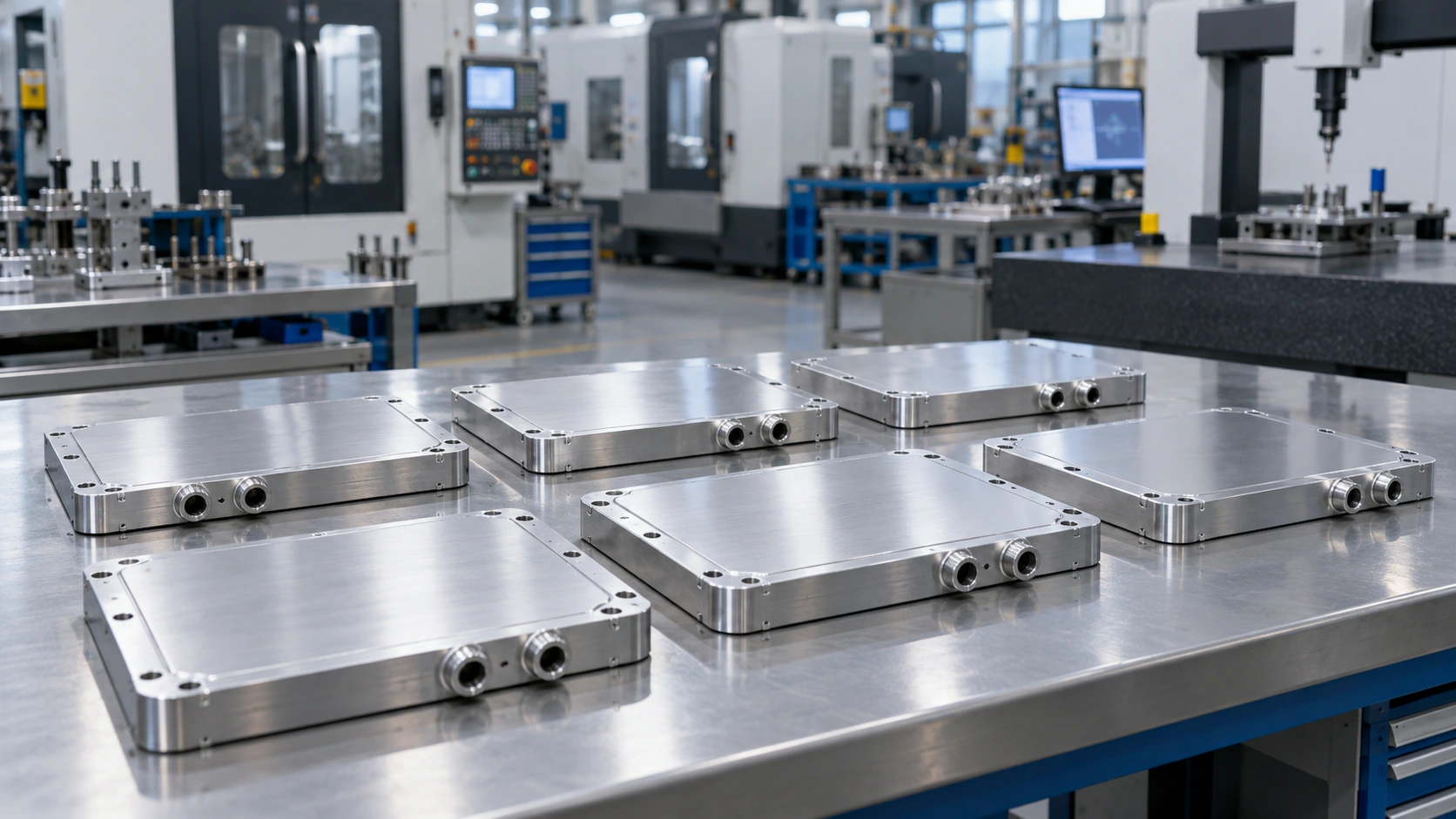
Let’s Engineer Your Next Cold Plate
Tell us about your equipment, heat load and cooling circuit. We will turn the inputs into a clear next step for design, sampling and validation.

Application-led engineering
Thermal, hydraulic and mechanical requirements reviewed together.

Controlled manufacturing
Qualified welding partners with Morton coordinating the complete part.

Documented validation
Drawing, first-article and leak-test requirements agreed before production.

One project contact
English technical communication from the first review to repeat supply.