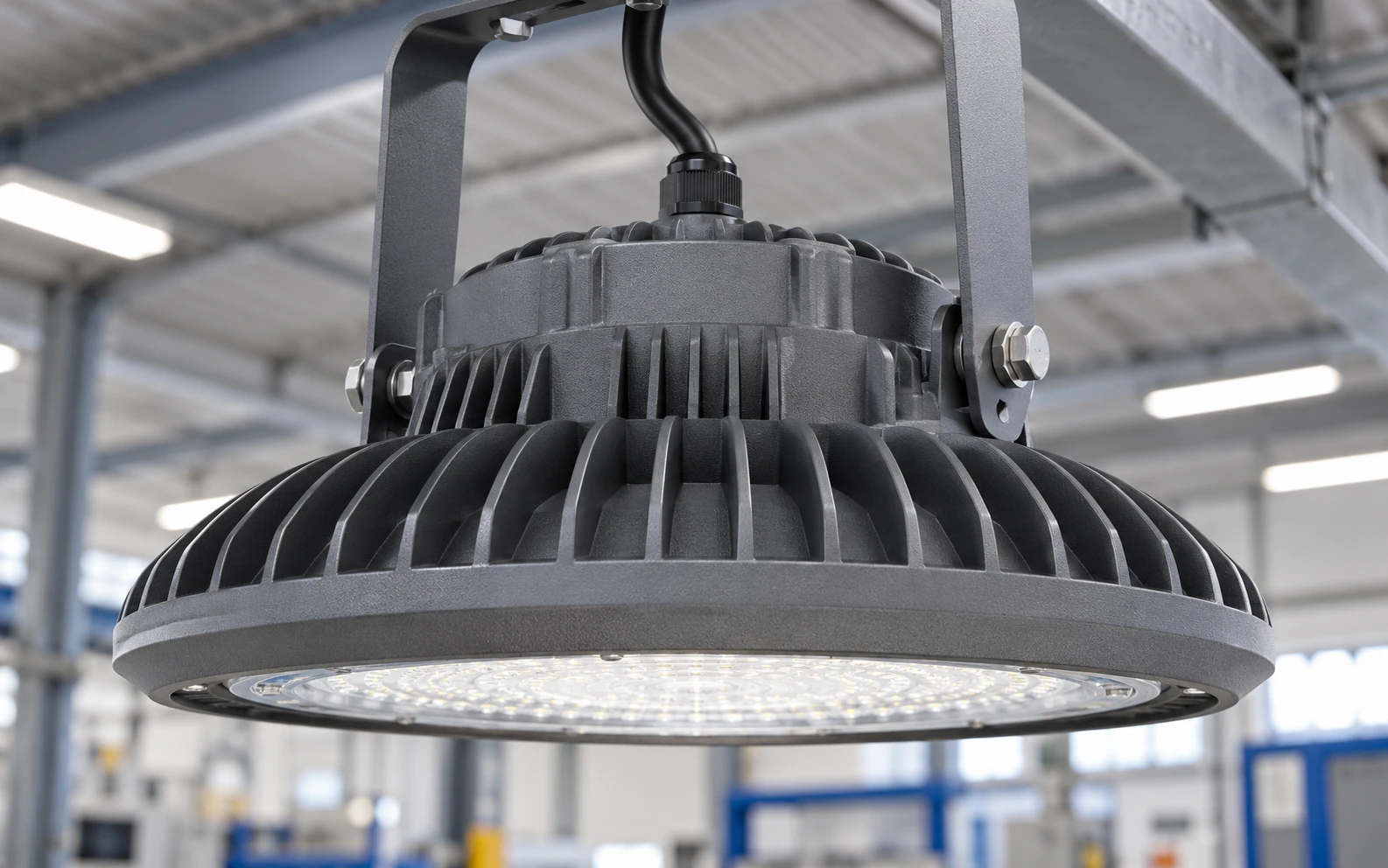
Industrial LED lighting
Integrate radial fins, mounting points and housing details around the LED thermal path.

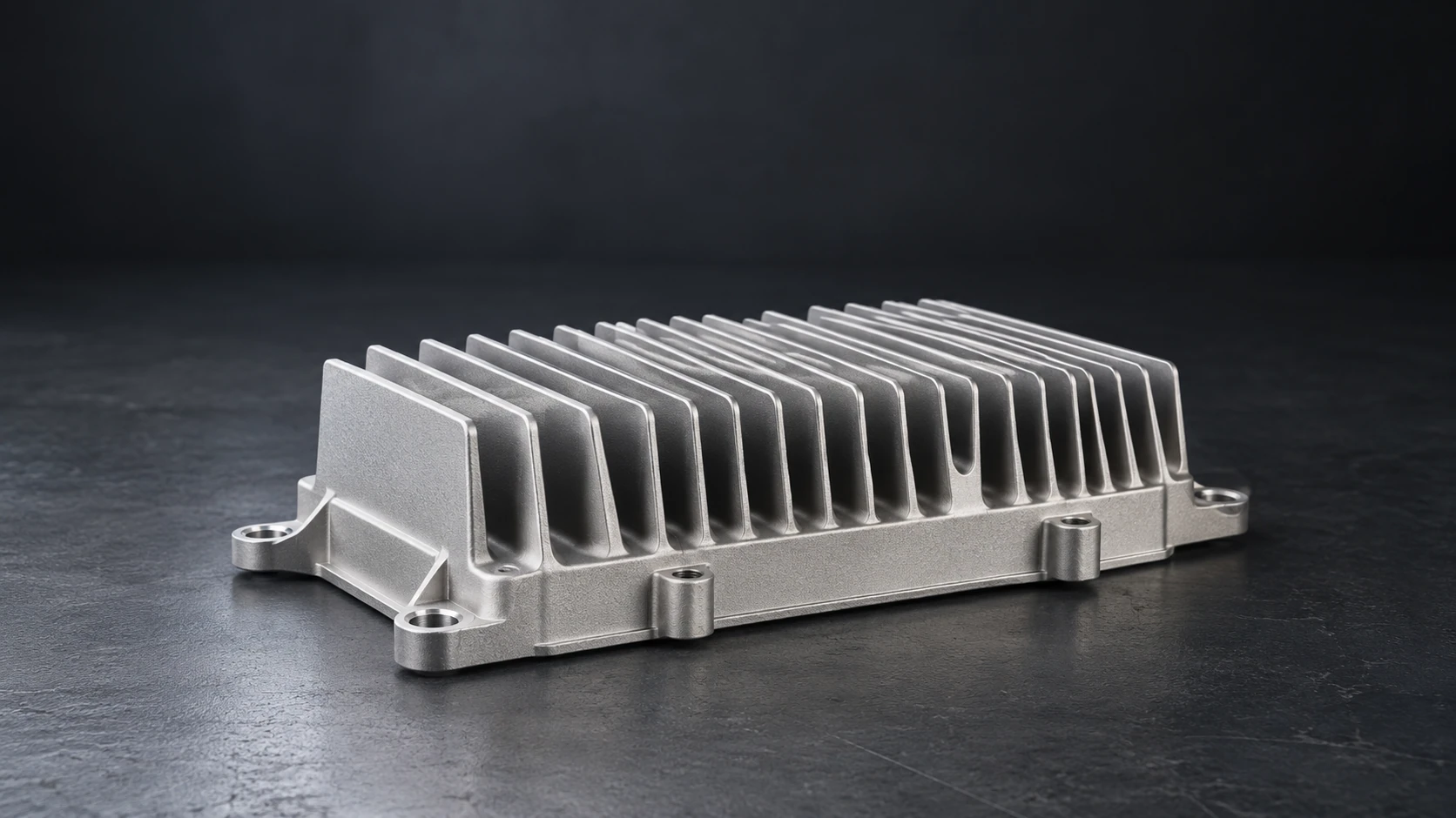
Integrate cooling fins, mounting features and structural details in one aluminum casting—engineered for your thermal load and repeat production.
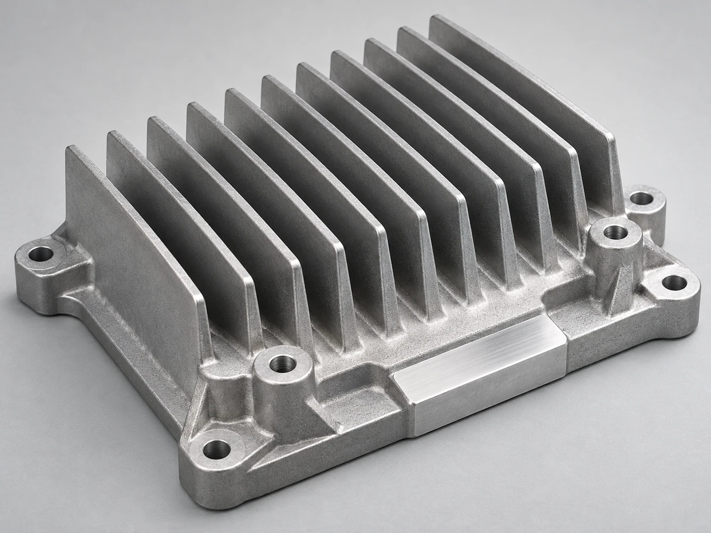
Die casting forms aluminum into complex, repeatable shapes so your heat sink can also support the mechanical assembly.
Share the space, heat source and mounting constraints for your next assembly.
Review My Product RequirementsUse the freedom of a casting to solve cooling, mounting and handling needs together.
Combine fins, ribs and fixing points in one body to simplify the bill of materials.
Place material and cooling area where the thermal path needs them.
Use defined datums and locating features to make production fit more consistent.
Amortize dedicated tooling across a stable product platform and annual demand.
Balance thermal conductivity, castability, strength and finishing requirements before the tool is committed.
| Alloy Route | Primary Application Focus | Engineering & Thermal Consideration |
|---|---|---|
| ADC12 | Complex cast geometry | Evaluate filling, strength and the thermal path together. |
| A380 | General structural castings | Review mechanical needs, processing and specified material data. |
| Specified high-conductivity aluminum | Thermally demanding designs | Select a qualified grade after casting trials and performance review. |
Evaluate filling, strength and the thermal path together.
Review mechanical needs, processing and specified material data.
Select a qualified grade after casting trials and performance review.
Thermal conductivity is taken from the specified alloy and condition. ADC12 and A380 are separate material specifications; the final grade is stated on the approved drawing.
Typical envelope: 50–400 × 50–400 × 10–120 mm (L × W × H); wall thickness: 2.5–6 mm. Review dimensions, alloy and fin geometry together for airflow, metal filling and reliable die release.
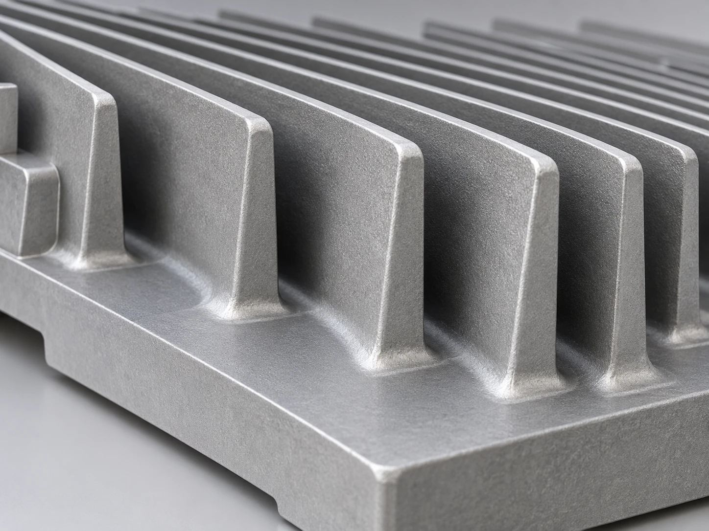
Set the taper, gap and height together so the casting can fill and eject reliably.
Use balanced sections and filleted roots to reduce abrupt changes in metal thickness.
Place parting lines, gates and ejector marks away from critical interfaces.
Reserve stock and accessible datums for the contact faces and precise installation features.
Catch tooling and thermal conflicts before they become expensive revisions.
Start a DFM ReviewThe useful result is the component temperature in your installation, with the heat source, interface and airflow defined.
Provide continuous and peak losses, contact area, layout and the permitted component temperature.
Review inlet temperature, mounting orientation, obstructions and the installed fan operating point where applicable.
Confirm base temperatures with the selected TIM, fastening method and actual installation conditions.
Base-to-air thermal resistance = (base hotspot temperature − inlet air temperature) ÷ effective heat load. Device junction temperature also includes the package and interface temperature rise.
Send your heat load and temperature limits for a practical thermal review.
Discuss Thermal RequirementsSecondary CNC machining defines the interfaces that control contact, alignment and assembly consistency.
Typical precision-finished target: ≤0.05 mm over 100 mm, reviewed against the drawing and clamping plan.
Precision contact surfaces can be finished to Ra 0.8–1.6 μm where the design requires it.
Selected local features can target ±0.02–0.05 mm within 100 mm after machining review.
Keep coating away from specified contact, grounding, thread and sealing areas.
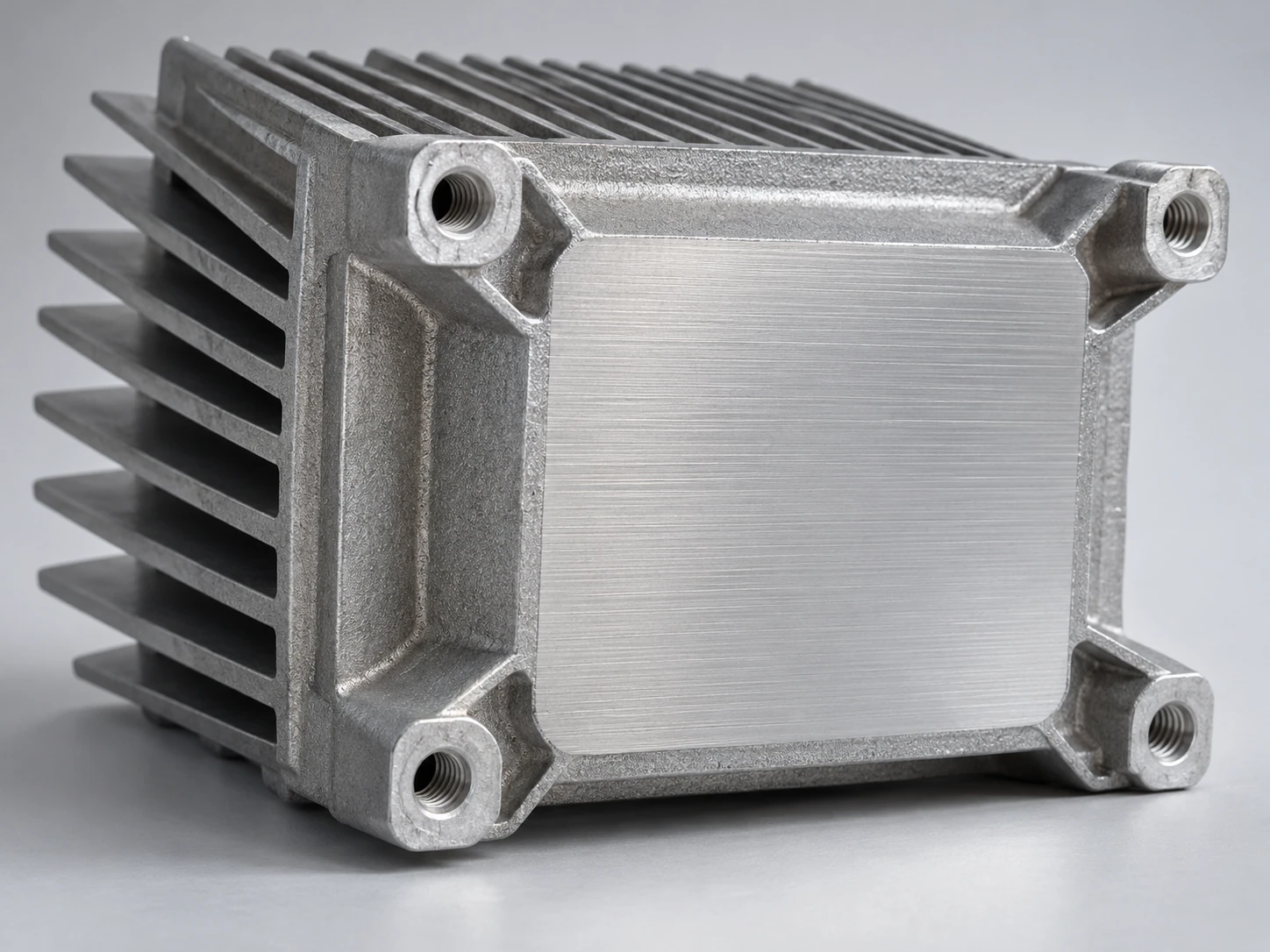
Mark your critical datums and contact faces so we can review them together.
Review My Critical InterfacesChoose corrosion protection and appearance while keeping the heat path, grounding and fit under control.
Retain a functional metal surface where the environment and appearance requirements allow.
Review corrosion protection and electrical contact requirements against the selected specification.
Specify coating thickness, color and mask boundaries so mating features remain usable.
Review alloy compatibility before specifying anodizing or another special finish for a silicon-rich casting.
Define the environment, appearance and masked surfaces before the first sample.
Plan My Surface SpecificationDie cast heat sinks are useful where a cooling body also needs to carry structural or mounting functions.
Integrate radial fins, mounting points and housing details around the LED thermal path.

Combine external cooling ribs with structural interfaces for compact outdoor electronics.
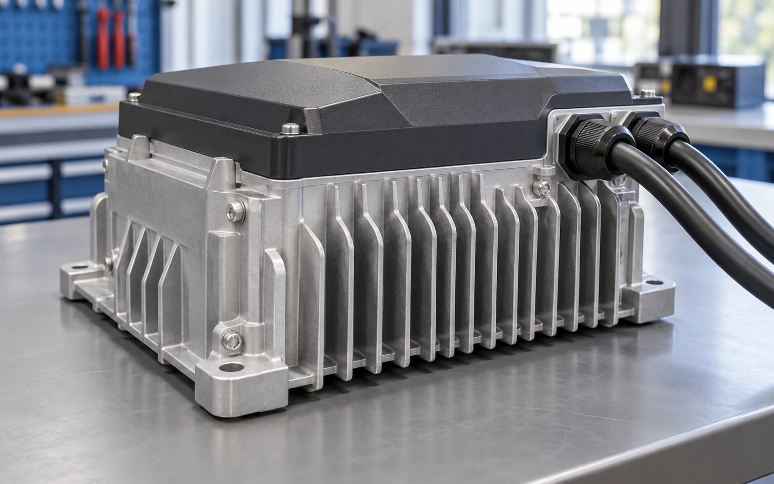
Place mounting bosses and contact surfaces around the power devices and available airflow.
One project team coordinates qualified casting partners, in-house precision machining and controlled inspection.
Freeze the alloy, envelope, heat source, critical interfaces and expected annual volume.
Agree the parting strategy, draft, gates, ejection and machining allowances.
Review filling, casting integrity and dimensions before sample approval.
Trim, deburr and machine approved contact faces, datums, holes and threads.
Apply specified finishes, verify masking and inspect drawing-defined characteristics.
Link approved samples, records, labels and packaging to the controlled drawing revision.
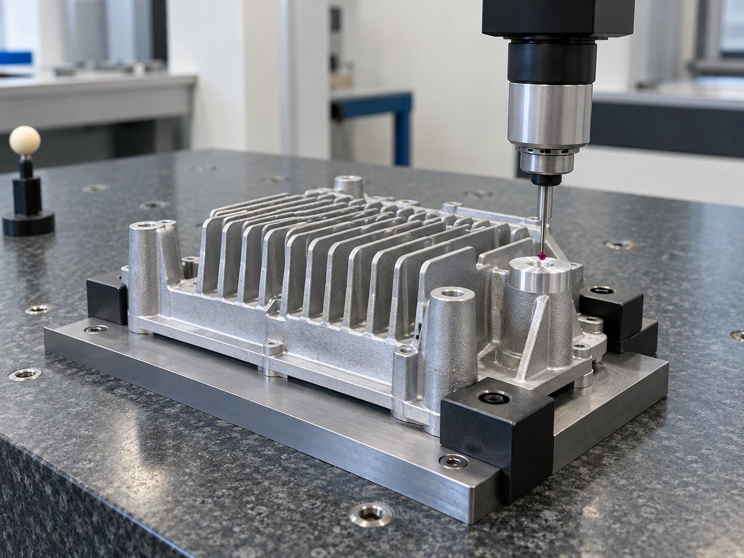
Tie material, dimensions and functional checks to the approved drawing and production lot.
Specified alloy, source records and batch traceability.
A dimensional report matched to the released drawing revision.
Defined visual and integrity checks; additional CT or sectioning when the project calls for it.
Flatness, roughness, thread and critical feature checks as specified.
Record the heat load, source area, inlet temperature, orientation and airflow.
Inspection records, part marking, packaging and engineering-change control.
Tell us the evidence your engineering and supplier-quality teams require.
Define My Inspection PlanAdapt the casting and its secondary operations to your thermal, mechanical and production requirements.
Match available space, heat-source position and the intended air path.
Place mounting, alignment and support details where the assembly needs them.
Define contact pads, datums, hole positions and threads from the approved drawing.
Specify color, coating thickness and surfaces that must remain uncoated.
Coordinate pads, fasteners and clamping requirements with the device interface.
Align identification, barcodes and protective packing with your receiving process.
Turn your assembly requirements into one controlled casting specification.
Discuss OEM CustomizationA clear cost and timing breakdown helps procurement compare the complete production route.
Typical starting quantity for a new die cast tool; final economic batch depends on geometry and tooling.
Typical new tooling and first-article approval window after the required project inputs are confirmed.
Reference die cast heat sink capacity, allocated against part size, processing time and the agreed schedule.
| Commercial Scope Phase | Key Engineering & Supply Deliverables |
|---|---|
|
Tooling and development
|
Tool ownership, trial scope, revisions and approval milestones. |
|
Recurring part cost
|
Material, casting, machining, finish, inspection and packaging. |
|
Release schedule
|
Forecast, batch size, lead time and shipment plan after sample approval. |
Share your annual demand and target launch date for a scoped quotation.
Request a Project QuotationResolve the material, tooling and validation questions before moving to samples.
It is a practical option when the part combines cooling fins with complex mounting or housing details and the expected volume can support dedicated tooling. The final choice also depends on thermal load and manufacturing constraints.
The specified alloy, geometry and thermal path need to be reviewed. Casting and wrought alloys have different properties, so matching the external size alone does not establish equivalent thermal performance.
Critical thermal contact faces, datums and selected holes can be CNC machined after casting. Required flatness, surface finish and tolerances are defined on the drawing.
A useful rating needs the heat-source area, inlet temperature, airflow or natural-convection orientation, interface material and temperature limit. We assess the part under the agreed operating conditions.
Send a STEP model and dimensioned drawing if available, the heat load and contact area, mounting envelope, target temperatures, finish, annual demand and target launch date.
The approved drawing, material specification, tooling scope and inspection plan define the baseline. Relevant changes are reviewed and approved before they enter repeat production.
Have a drawing-specific question? Bring it to the engineering review.
Ask a Die Casting Question
Share the heat load, geometry and production goal. Our team will review the fit and outline a practical next step.