
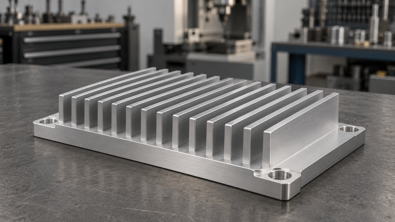
CNC Machined Heat Sinks
Precision aluminum and copper heat sinks engineered around your thermal interface, mounting geometry, and production requirements.
Custom interfaces
Machined to your approved drawing.
Prototype to production
Start with functional samples, then scale with a controlled process.
Aluminum & copper
Select the material around thermal and mechanical priorities.
Bring your drawing and operating conditions to our engineering team.
Request an Engineering Review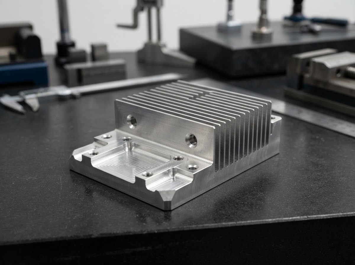
Precision Cooling, Machined Around Your Design
A CNC machined heat sink removes material from aluminum or copper stock to combine heat transfer surfaces and precise mechanical features in one custom component.
Combine fins, contact lands, pockets, and mounting features to reduce assembly interfaces.
Control the geometry around board clearances, component heights, and enclosure boundaries.
Create prototypes and small production batches without a dedicated casting or forging die.
Turn a space-constrained concept into a manufacturable thermal component.
Discuss Your Heat Sink DesignWhen Standard Profiles Cannot Meet the Brief
Choose CNC machining when installation details and project flexibility matter as much as the external envelope.
Complex mounting geometry
Place steps, bosses, slots, and fasteners around the actual assembly to simplify installation.
Multiple contact heights
Machine contact lands to reach devices at different levels while respecting surrounding keep-out zones.
Tight mechanical interfaces
Define local datums and critical dimensions so the approved heat sink fits repeatably.
Evolving development requirements
Revise CAD between sample stages before committing to higher-volume tooling.
Show us the details a standard profile cannot accommodate.
Review Your Mechanical RequirementsThe Right Metal for Your Thermal Priorities
Balance thermal conductivity, machinability, weight, surface treatment, and part cost before freezing the material specification.
6061-T6 aluminum
Approx. 167 W/(m·K) at room temperature. A practical choice for rigid mounting features, precision pockets, and structural integration.
6063 aluminum
Approx. 200 W/(m·K) at room temperature. Useful when thermal conductivity and a suitable stock form support the final geometry.
C1100 copper
Approx. 390 W/(m·K) at room temperature. Supports demanding heat spreading where the added mass and machining cost are acceptable.
Choose a material around the complete assembly, not conductivity alone.
Compare Material OptionsIntegrate the Features Your Assembly Needs
Consolidate thermal and mechanical details in the same machining plan to reduce secondary parts and fitting work.
Stepped contact lands
Match device heights with defined thermal contact areas.
Mounting holes & threads
Locate fasteners from shared datums for consistent fit.
Pockets & keep-outs
Clear board components and connectors without sacrificing essential base thickness.
Machined fins & airflow slots
Set accessible channels around the available airflow and tool reach.
Locating features
Use shoulders, reference edges, and dowel features to control assembly position.
Edge finishing
Specify deburring and edge breaks for cleaner handling and installation.
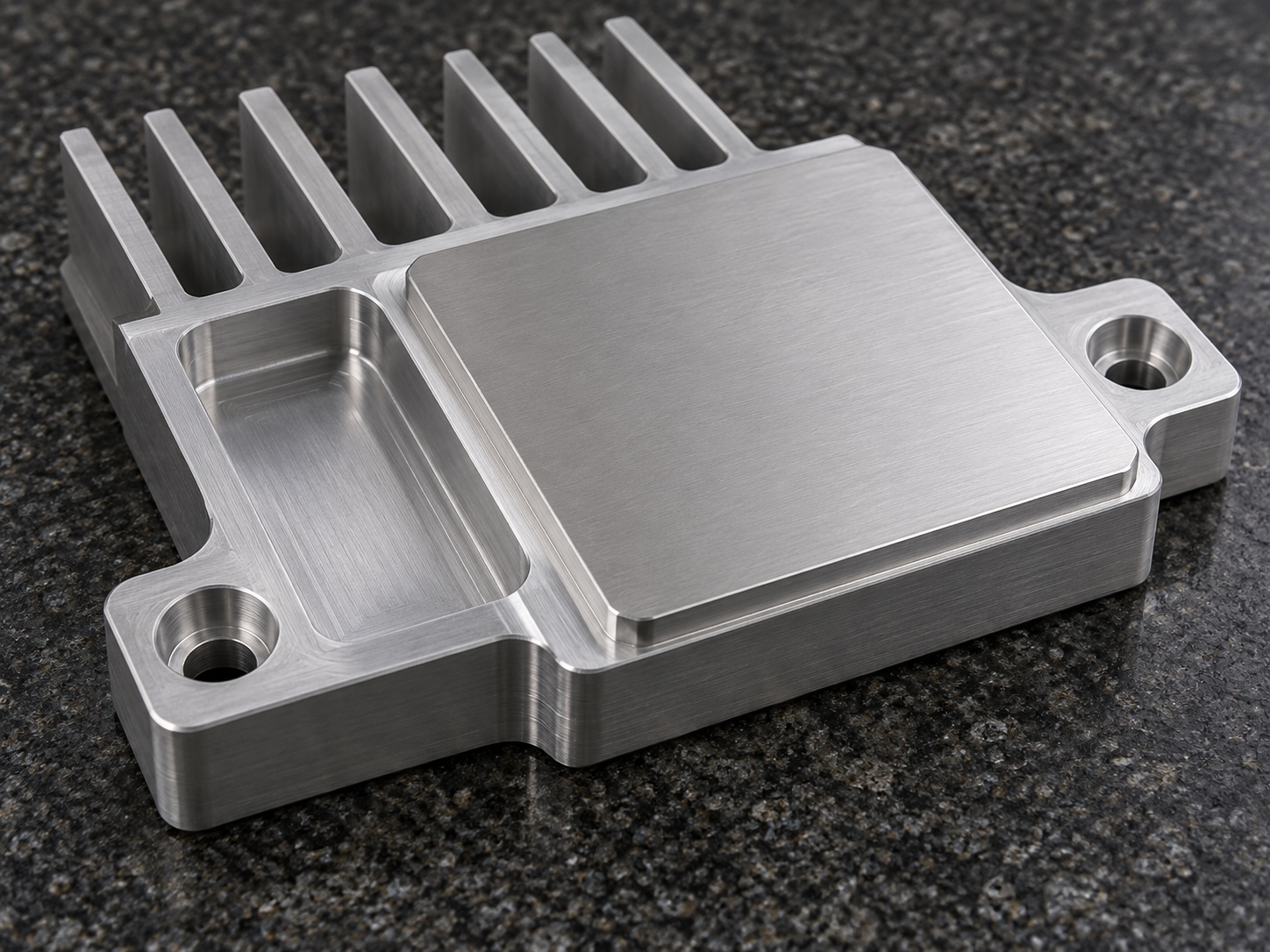
Control the Interface That Controls the Fit
Define critical features locally, then align the machining datum, fixture strategy, and inspection plan with the finished assembly.
| Item | Range / Specification | Application / Purpose |
|---|---|---|
| Machining envelope | 600 × 900 × 180 mm | typical envelope; large parts reviewed by operation and setup. |
| Critical local dimensions | ±0.02–0.05 mm within 100 mm, | based on accessible features and the approved drawing. |
| Contact-face flatness | Typically ≤0.05 mm over 100 mm | for a precision-machined contact area. |
| Thermal-face finish | Ra 0.8–1.6 μm | available on specified precision contact surfaces. |
Make the Heat Path Work as a System
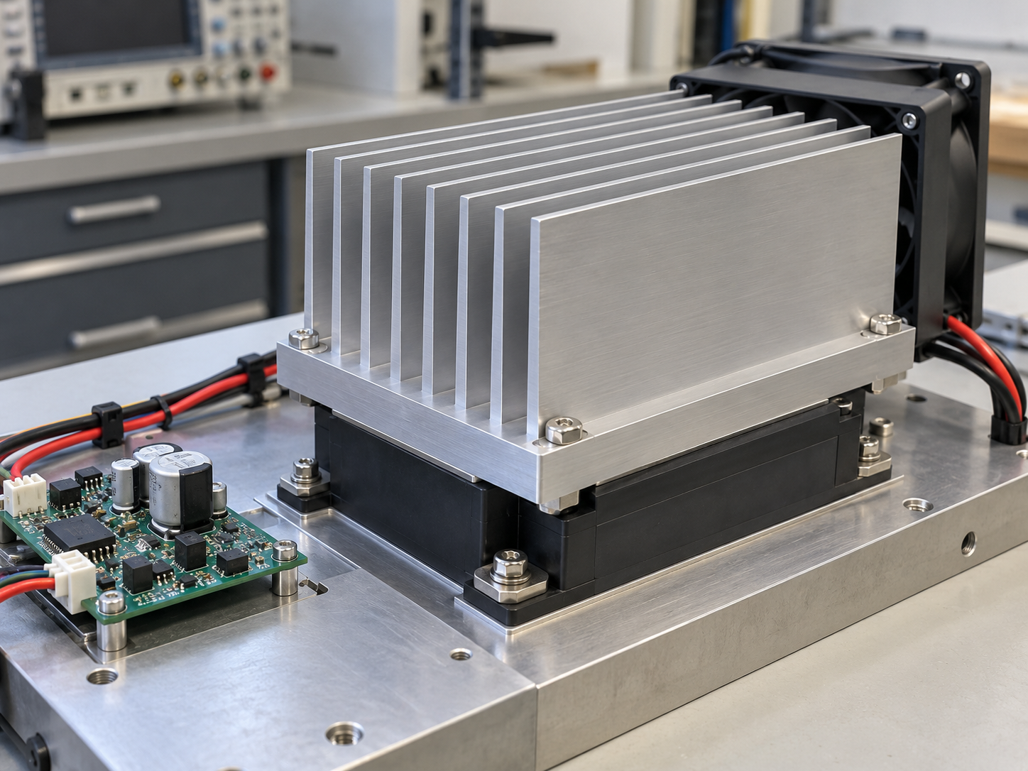
Fin geometry, base thickness, interface material, and actual airflow must work together to keep the heat source within its temperature target.
Define the heat source
Share continuous and peak losses, contact area, source locations, and allowable device temperature.
Match the installed airflow
Review fin spacing, flow direction, bypass paths, and the fan operating point inside the enclosure.
Validate the real interface
Confirm contact pressure, TIM thickness, inlet temperature, and measurement locations in the test setup.
Build a thermal requirement that can be tested and repeated.
Discuss Your Thermal ConditionsDesign for Machining Before You Cut Metal
Early DFM review keeps precision where it adds value and removes machining complexity that does not improve the finished assembly.
Tool access & internal radii
Allow a practical cutter path and corner radius to reduce deep-pocket machining time.
Fin stiffness & reach
Review fin height, spacing, wall thickness, and tool overhang together to protect delicate features.
Datums & setup count
Group critical features around stable reference surfaces to limit repeated reclamping.
Functional tolerances
Apply tight limits to contact and locating features while keeping noncritical geometry economical.
Resolve the expensive details while a CAD revision is still simple.
Start a DFM ReviewFinish for the Environment and the Interface
Specify the finish together with contact faces, grounding points, threads, and final dimensional requirements.
Natural machined finish
Keep a clean metallic surface where the application and handling requirements allow.
Anodized aluminum
Use natural, black, or specified colors; mask thermal contact and grounding areas as required.
Chemical conversion
Consider conversion coatings where corrosion resistance and electrical contact must be balanced.
Specified nickel plating
Evaluate copper protection, coating compatibility, and final interface dimensions as part of the drawing.
Define the surfaces that need protection and those that must remain functional.
Review Surface RequirementsPrecision Thermal Parts for Demanding Equipment
Custom machining helps OEM teams fit reliable air-cooled thermal components into equipment with demanding mechanical constraints.
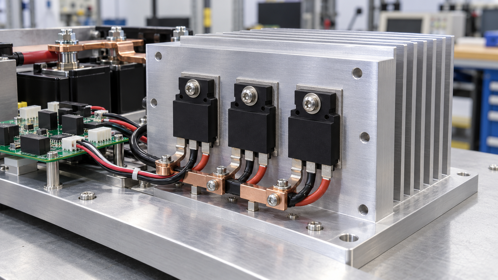
Industrial power electronics
Custom mounting lands and clearance pockets for power supplies, converters, and compact drive assemblies.
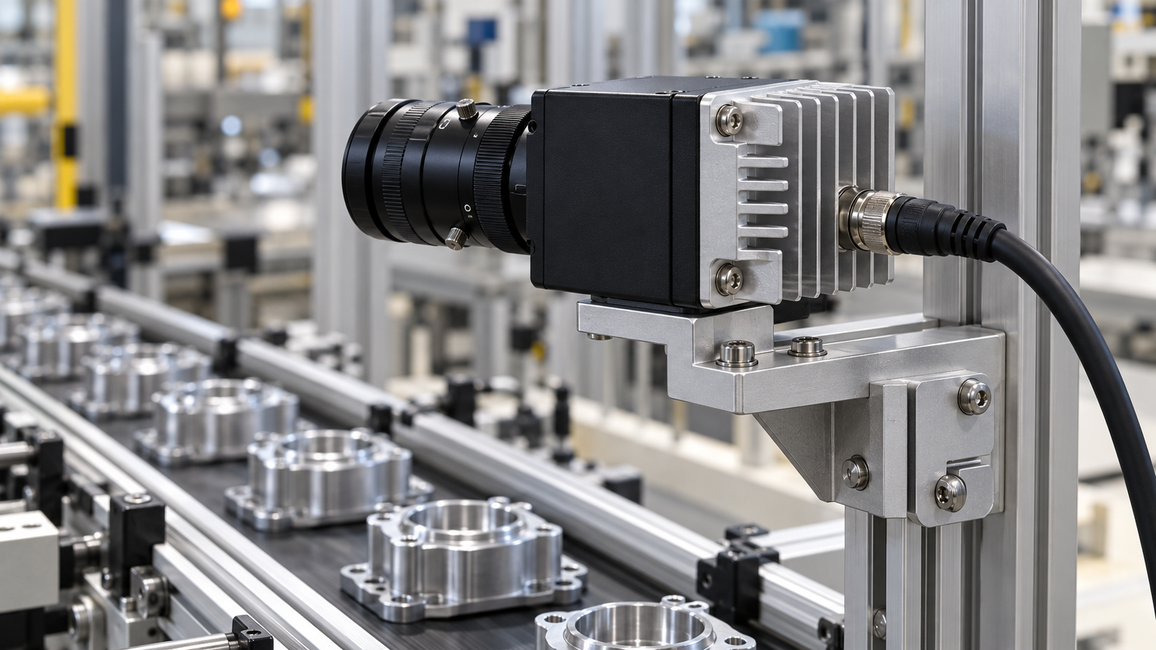
Machine vision & automation
Precision contact heights and locating features around processors, sensors, and densely packed control electronics.
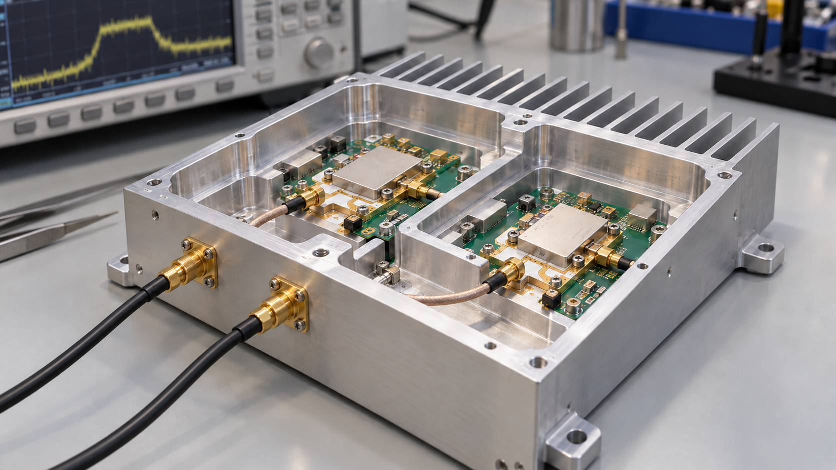
Telecommunications equipment
Aluminum or copper thermal parts matched to RF modules, amplifier interfaces, and enclosure boundaries.
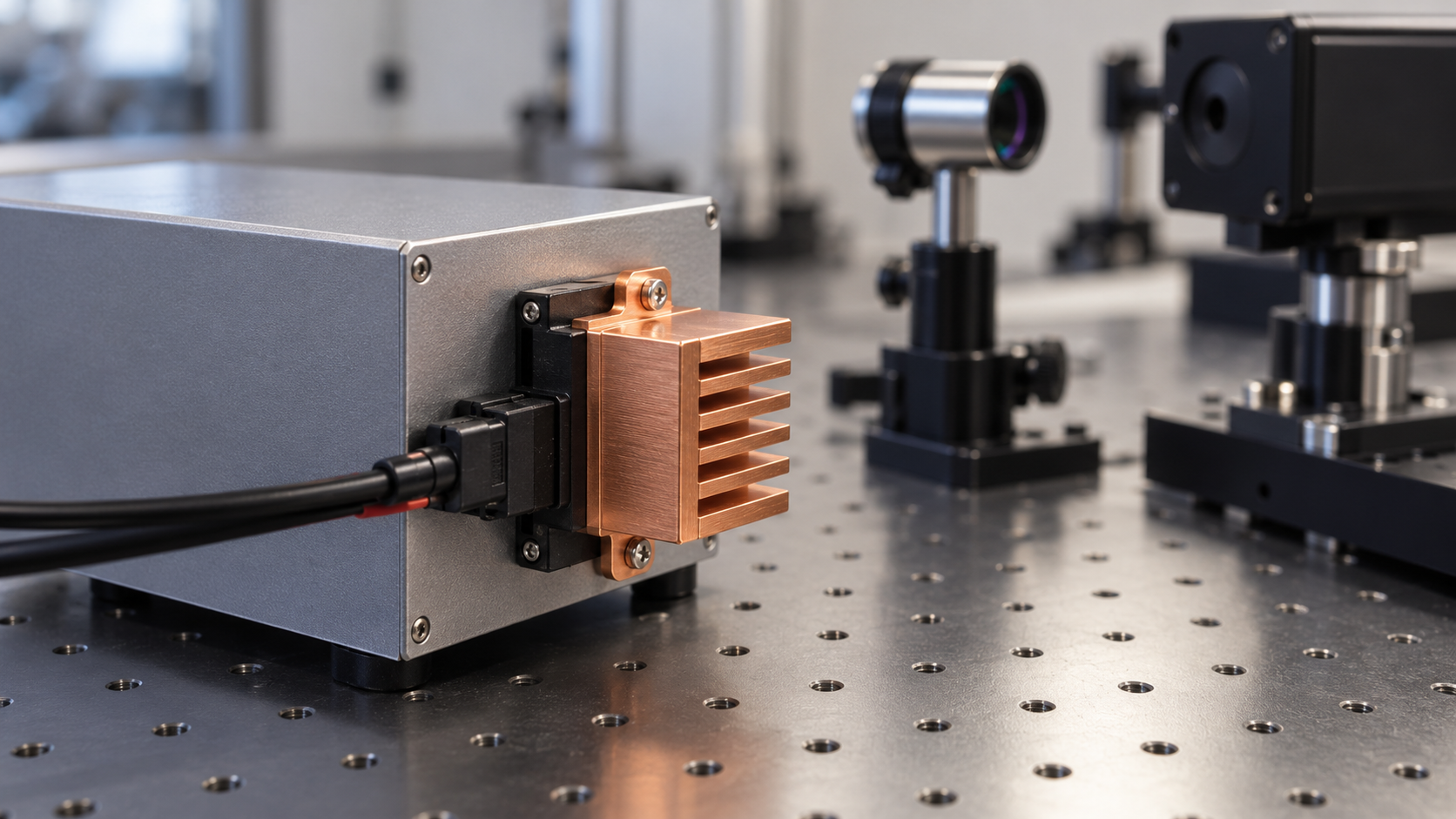
Laser & precision instruments
Stable machined interfaces for driver electronics and temperature-sensitive instrument assemblies.
Tell us how your equipment constrains the thermal design.
Discuss Your Application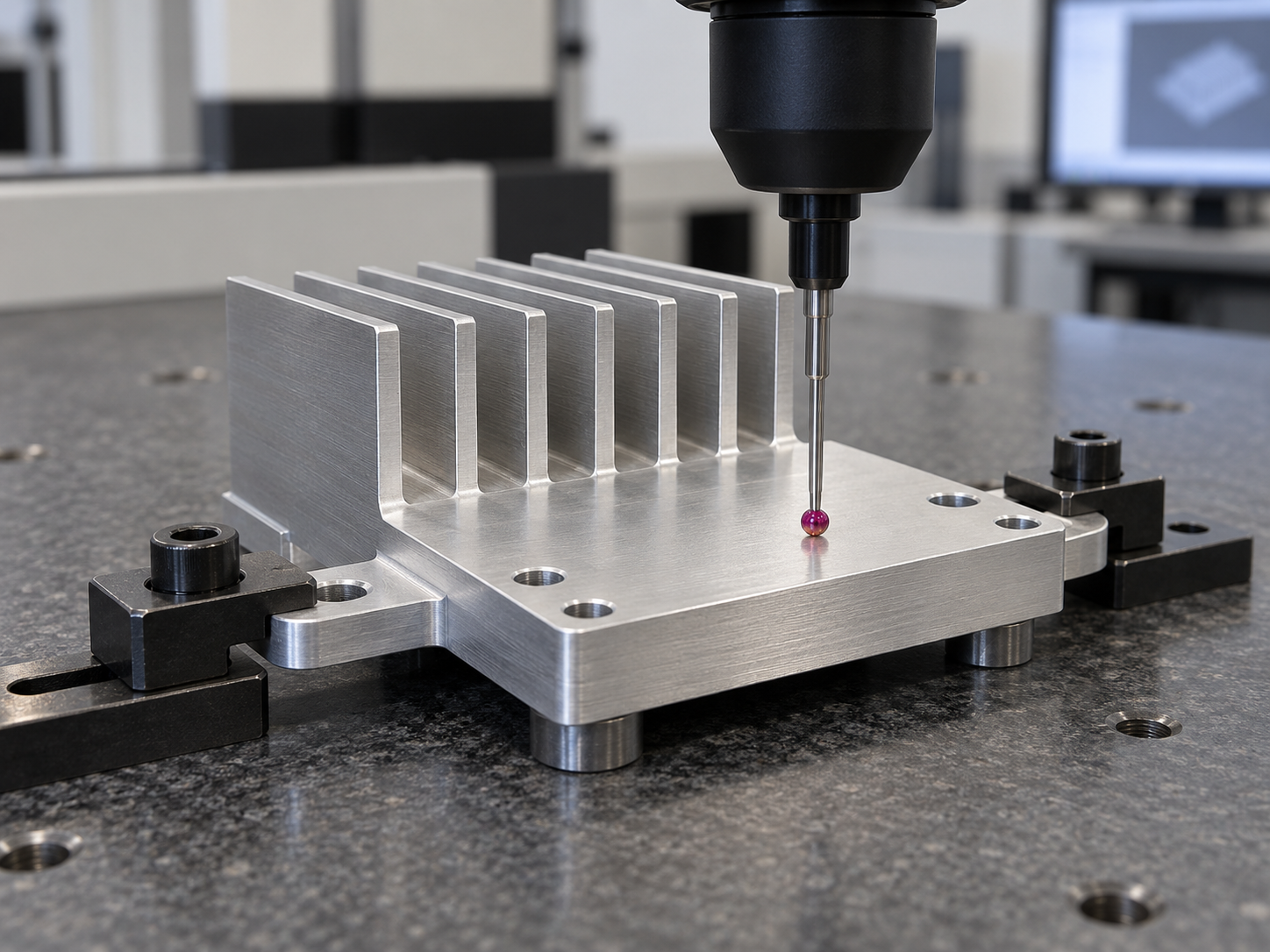
Inspection Built Around Critical Features
Connect the material, machining, surface treatment, and final inspection records to the same approved drawing revision.
Material verification
Check alloy specification and batch identity before machining.
First-article approval
Verify datums, hole positions, contact faces, and fit-critical dimensions before batch release.
In-process control
Monitor fixtures, key features, threads, and burr removal during production.
Final release & traceability
Inspect the finished condition and link approved records to the work order and material batch.
Turn your critical features into an agreed inspection plan.
Discuss Quality RequirementsA Clear Route from CAD to Approved Parts
Keep engineering, procurement, and quality aligned through a controlled sample-to-production process.
01 · Review
Provide CAD, drawings, heat load, space limits, finish, and expected volume for feasibility and quotation.
02 · Prototype
Produce functional samples and document the dimensions that define the assembly.
03 · Validate
Review fit and thermal performance under agreed operating conditions, then freeze the drawing revision.
04 · Release
Approve the control plan, packaging, and delivery schedule for repeat production.
Start with the design information you already have.
Plan Your PrototypeEngineering Support with Manufacturing Capacity
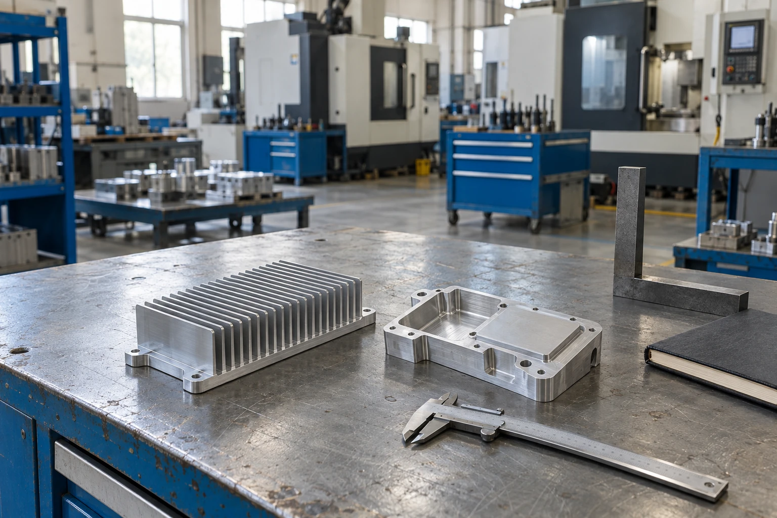
Morton connects engineering review, CNC machining, inspection, and export coordination through one project team.
CNC Heat Sink Questions, Answered
Clarify the practical engineering and purchasing details before requesting a custom quotation.
What do you need to quote a custom heat sink?
Can you support a one-piece prototype?
Is ±0.02 mm available across the entire part?
Can you machine both fins and mounting features?
Can the thermal contact face remain uncoated?
How is thermal performance confirmed?
Let’s Build Your Next Precision Heat Sink
Share your drawing, thermal requirements, or mechanical constraints. Morton will help turn them into a practical machining and supply plan.
Drawing-led engineering
Review material, geometry, datums, and fit-critical features.
Aluminum & copper options
Choose around heat spreading, weight, rigidity, and cost.
Functional prototypes
Validate fit and thermal contact before batch approval.
Documented quality
Align first articles, critical checks, and batch traceability.
Repeat OEM supply
Plan controlled revisions and scheduled production together.
Request Your Engineering Review
Tell us the essentials. Detailed drawings can be shared during our technical follow-up.