
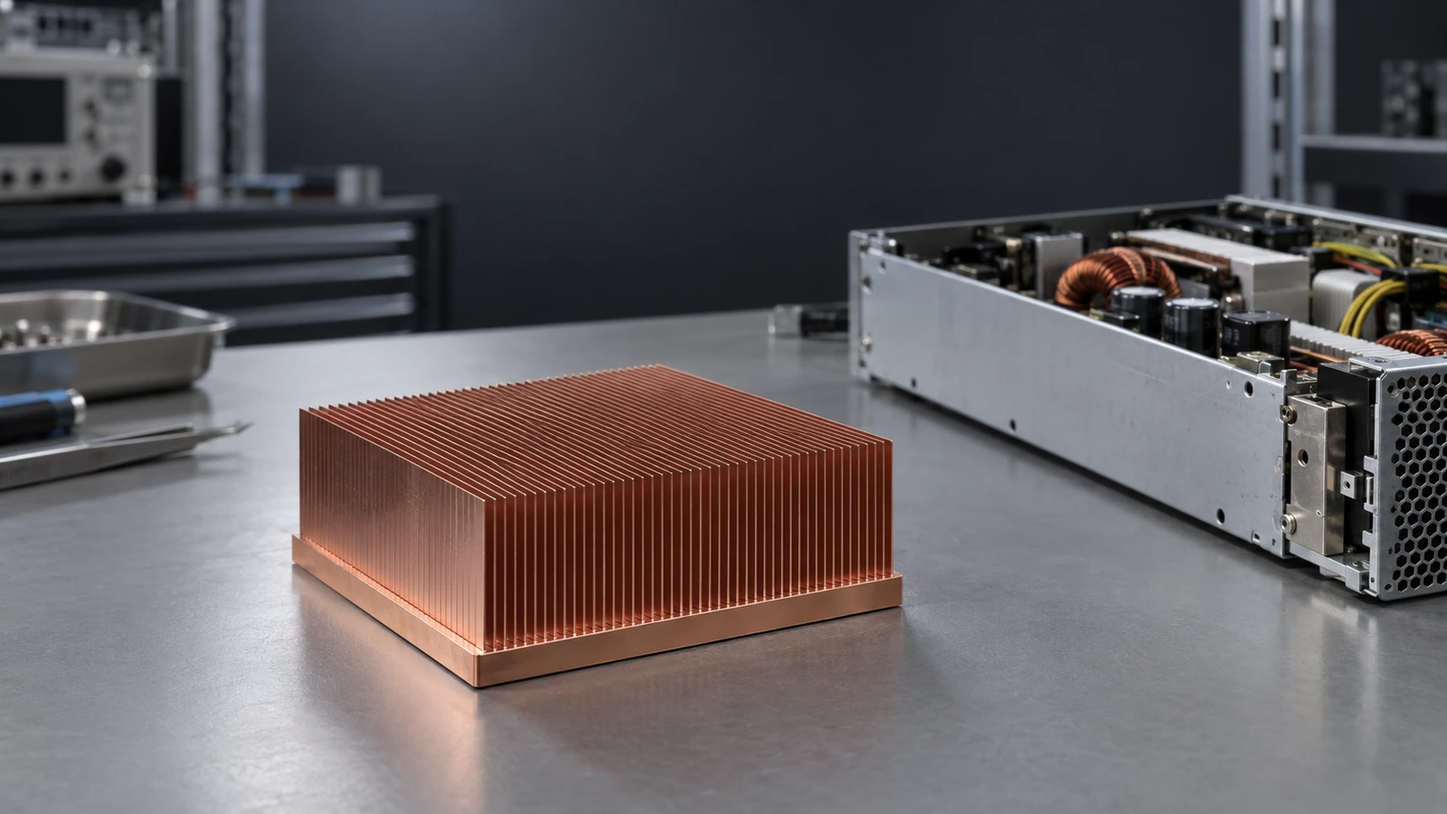
Copper Skived Fin Heat Sink for Server Power Supplies
How a German server PSU OEM reduced a 250 W hotspot from 82.5°C to 70°C within a 100 × 100 × 35 mm envelope.
Bring a proven thermal approach to your next PSU design.
Discuss My PSU CoolingA Compact PSU. A Clearly Defined Thermal Target
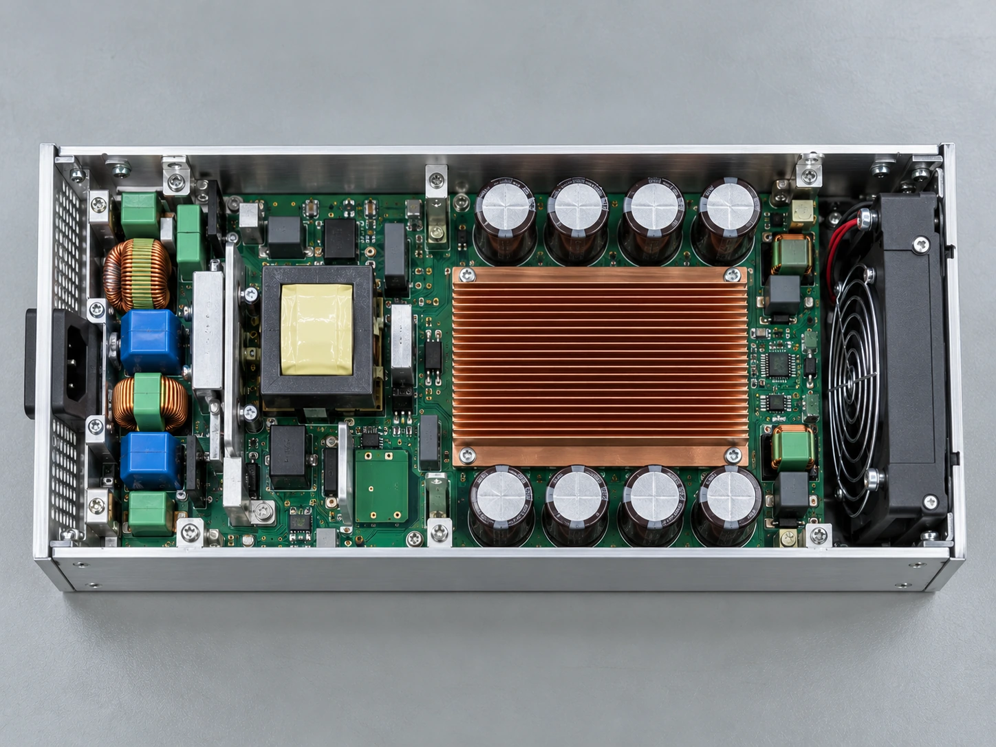
A German server power supply OEM needed more thermal headroom without increasing its cooling envelope.
The project focused on a concentrated 30 × 30 mm heat source inside a forced-air server PSU. The cooling component had to fit the existing mechanical space and work with the installed airflow.
Acceptance target: base hotspot below 75°C.
Start with the same boundary conditions your system will see.
Share My Project ConditionsWhy the Original Thermal Design Missed the Limit
The original structure reached about 82.5°C at the base hotspot, exceeding the project limit by 7.5 K.
Localized heat spreading
A small heat source concentrated 250 W into the base, making the heat path into the fin area critical.
Restricted airflow
Increasing fin density alone could raise flow resistance and move the fan away from the required operating point.
Contact consistency
The interface layer and mounting load needed control so the thermal result could be repeated across assemblies.
Solve the heat path, airflow and interface as one system.
Review My Thermal Bottleneck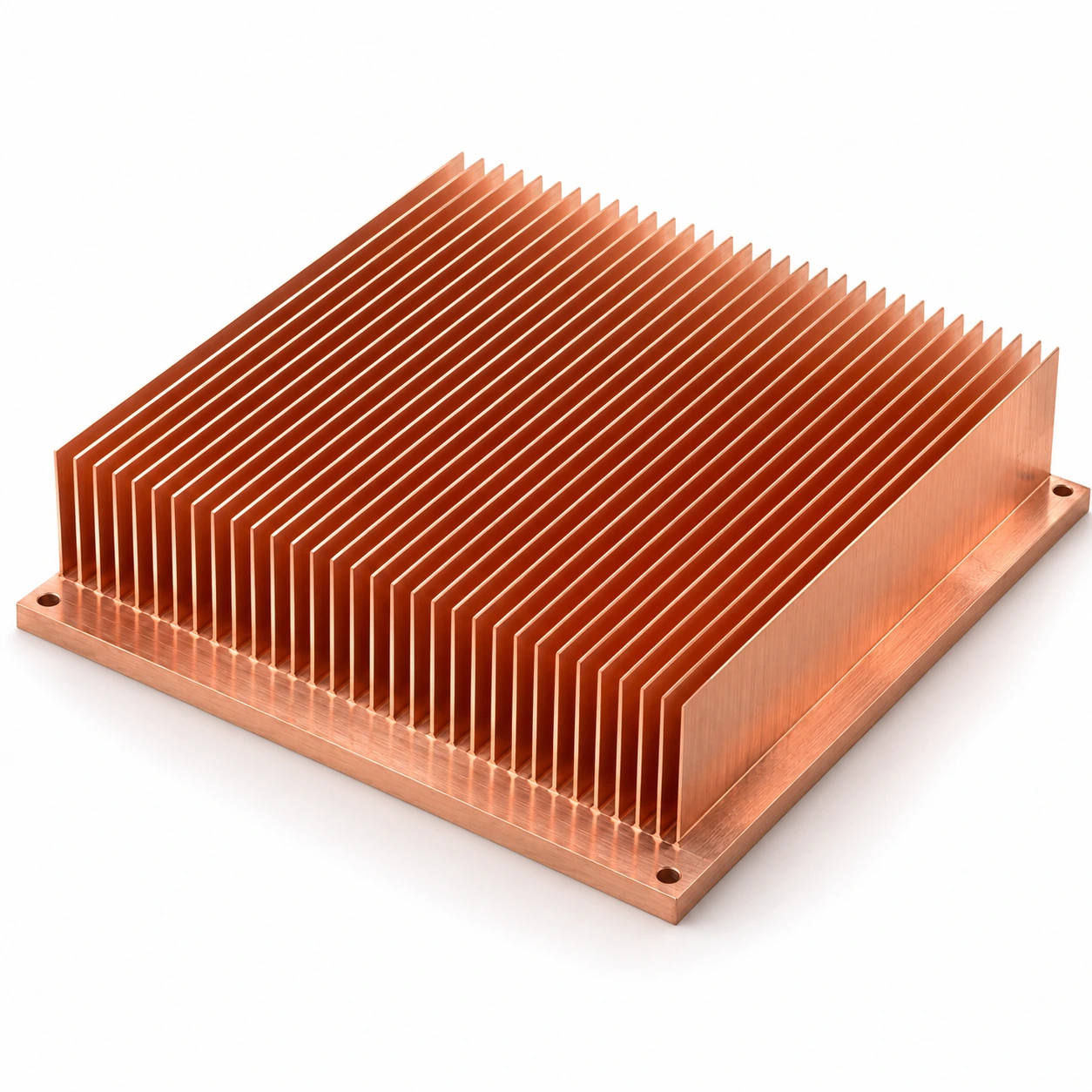
Continuous copper fins and base; precision-machined mounting interface.
One Copper Body. A Shorter Path from Hotspot to Air
A C1100 copper skived-fin heat sink combined a continuous fin-to-base structure with controlled mounting contact.
Match the copper geometry and interface to your actual heat source.
Request a Skived-Fin Design ReviewThe Fin Stack Was Matched to the Installed Airflow
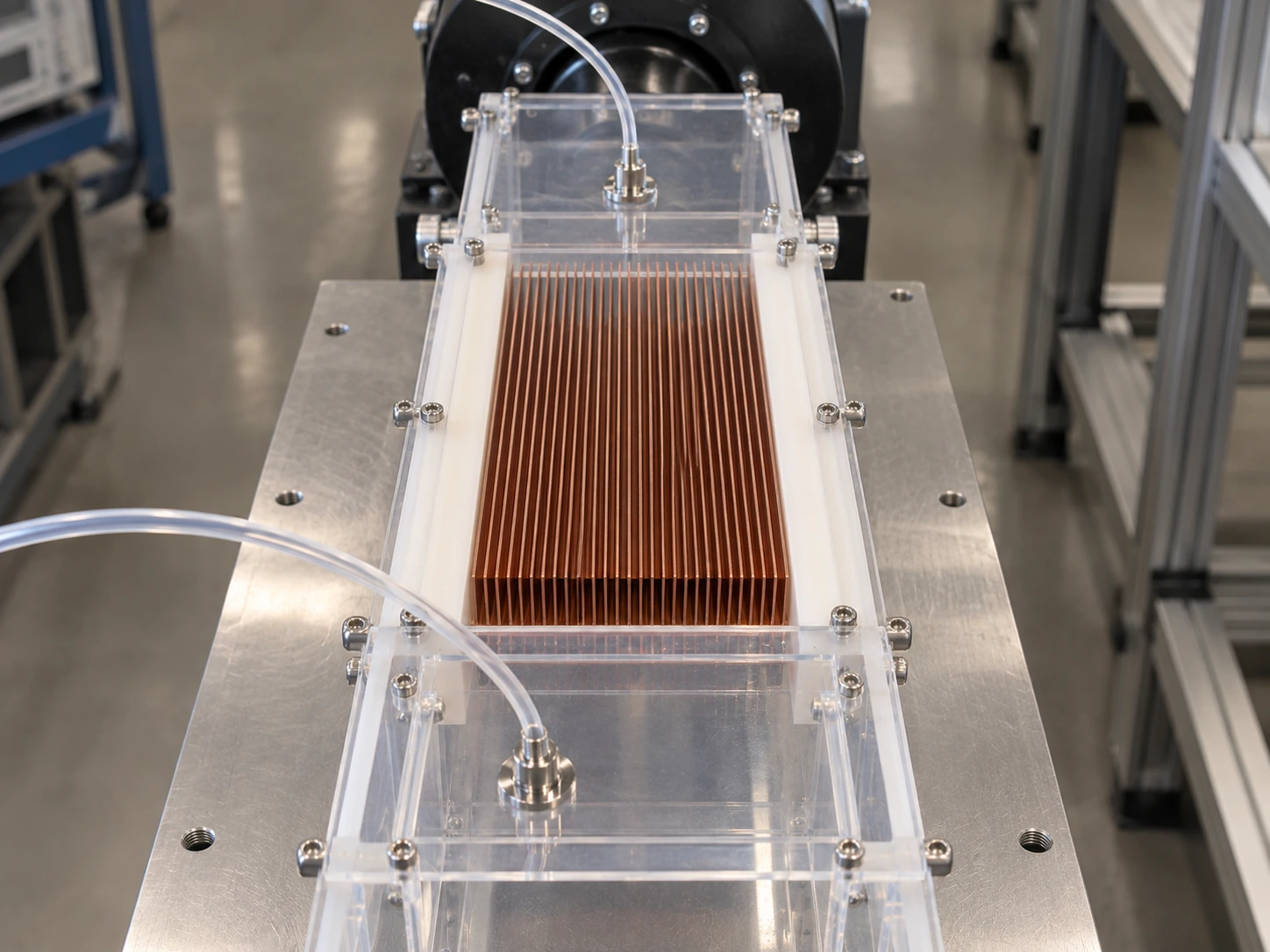
The design used measured flow through the heat sink, together with the fan pressure–flow curve, to confirm the operating point.
The inlet guide reduces bypass and directs air through the active fin passages.
The fan curve is assessed against the assembled flow resistance, rather than its free-air rating.
The report captures measured airflow through the fins and the air-side pressure drop.
Use the fan operating point your installed system can deliver.
Check My Airflow RequirementsLower Hotspot Temperature. More Thermal Headroom
Under the same installation and measurement conditions, the revised heat sink brought the base hotspot below the 75°C limit.
| Configuration | Base Hotspot | Thermal Resistance (Rθ) | Compliance Status |
|---|---|---|---|
| Original structure | 82.5°C | 0.23 K/W | Exceeded by 7.5 K |
| Copper skived-fin design | 70°C | 0.18 K/W | Passed with 5.0 K Margin |
Comparison conditions: 250 W; 30 × 30 mm heat source; 25°C inlet air; 60 m³/h measured through the fins; same installation and measurement method.
Judge thermal improvement against a repeatable set of conditions.
Discuss My Thermal Target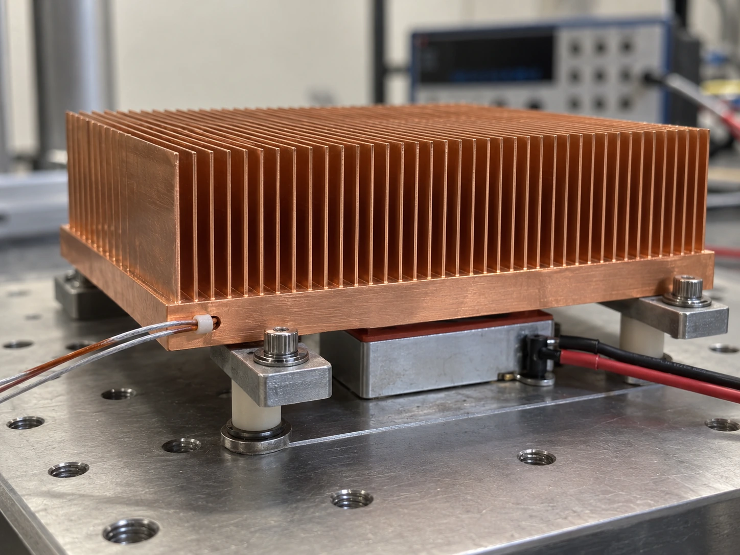
A Result Your Engineering Team Can Reproduce
The validation record ties the thermal result to defined sensor locations, airflow, interface and steady-state criteria.
Sensor map
Locations linked to the test setup.
Flow and pressure record
Installed airflow and air-side pressure drop.
Steady-state record
Stable readings and the applied acceptance criterion.
From an Approved Sample to a Repeatable Build
Material, fin geometry, contact surfaces and assembly conditions are carried into a controlled production specification.
Verify the copper lot
C1100 material specification and batch identity follow the manufacturing record.
Control the skived geometry
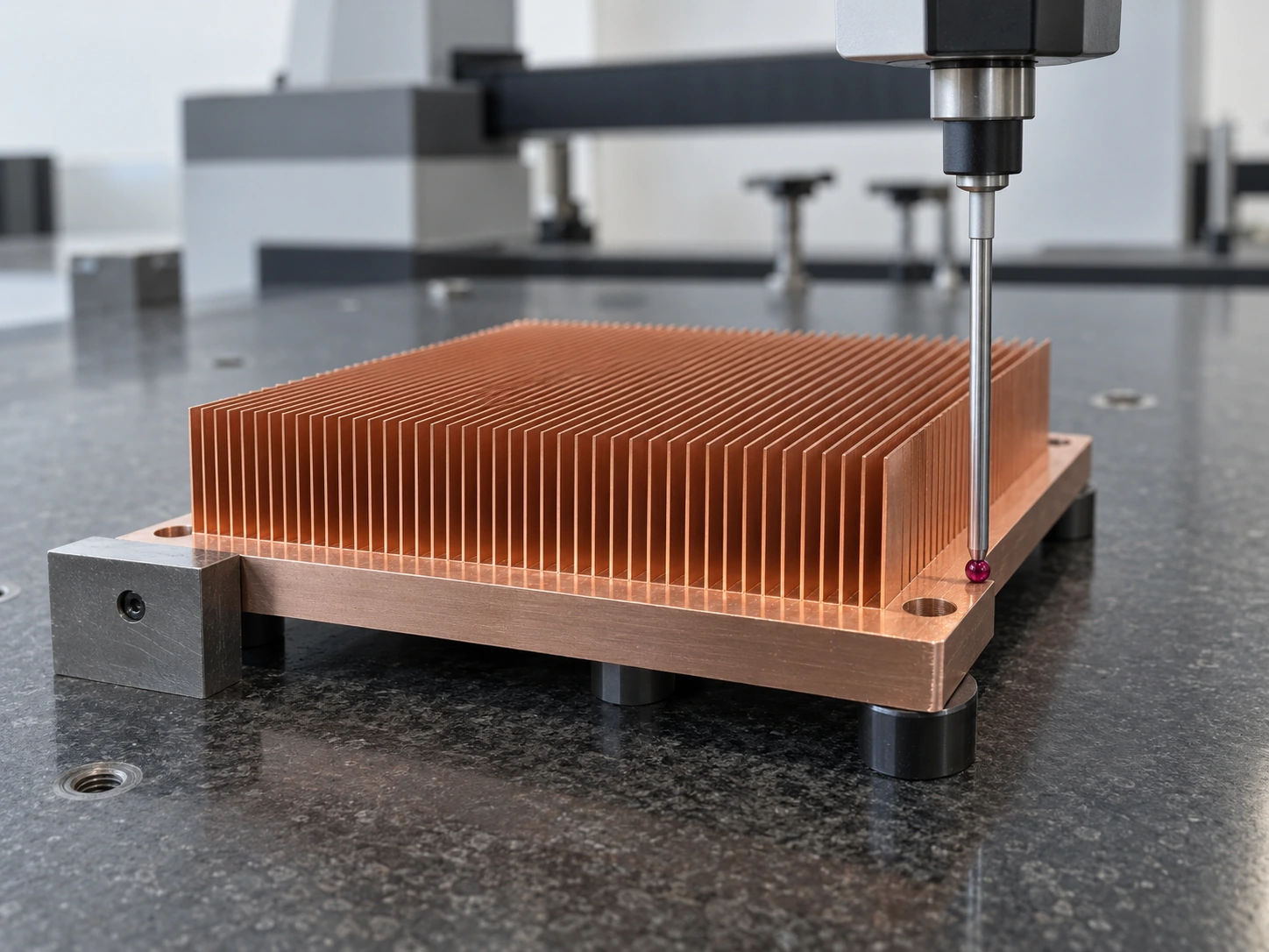
Fin thickness, clear spacing and fin condition are checked against the approved drawing.
Inspect the mounting interface
Contact surface, hole positions and mounting features are verified in first-article inspection.
Release against the approved build
Thermal sampling, identification and protective packaging follow the control plan.
Qualified for Supply. Ready for Repeat Orders
The validated design progressed into a 1,200-unit first delivery, followed by rolling monthly replenishment.
For engineering
- A defined thermal acceptance condition
- An approved drawing and assembly specification
- A repeatable reference for incoming checks
For procurement
- Batch-linked material and inspection records
- Protective packaging for thin copper fins
- A rolling release plan for recurring demand
Turn a validated cooling component into a dependable supply item.
Plan My Sample-to-Production Path
Bring Your Server PSU Thermal Challenge to Morton
Share your heat load, space envelope and airflow. Our engineers will help define the next practical step.
Application-focused engineering
Heat source, airflow and mounting reviewed together.
Prototype support
Development samples for fit and thermal validation.
Condition-defined thermal data
Results tied to the approved test conditions.
First-article documentation
Dimensions and critical features linked to the drawing.
Controlled production transfer
Material, process and inspection requirements carried forward.