
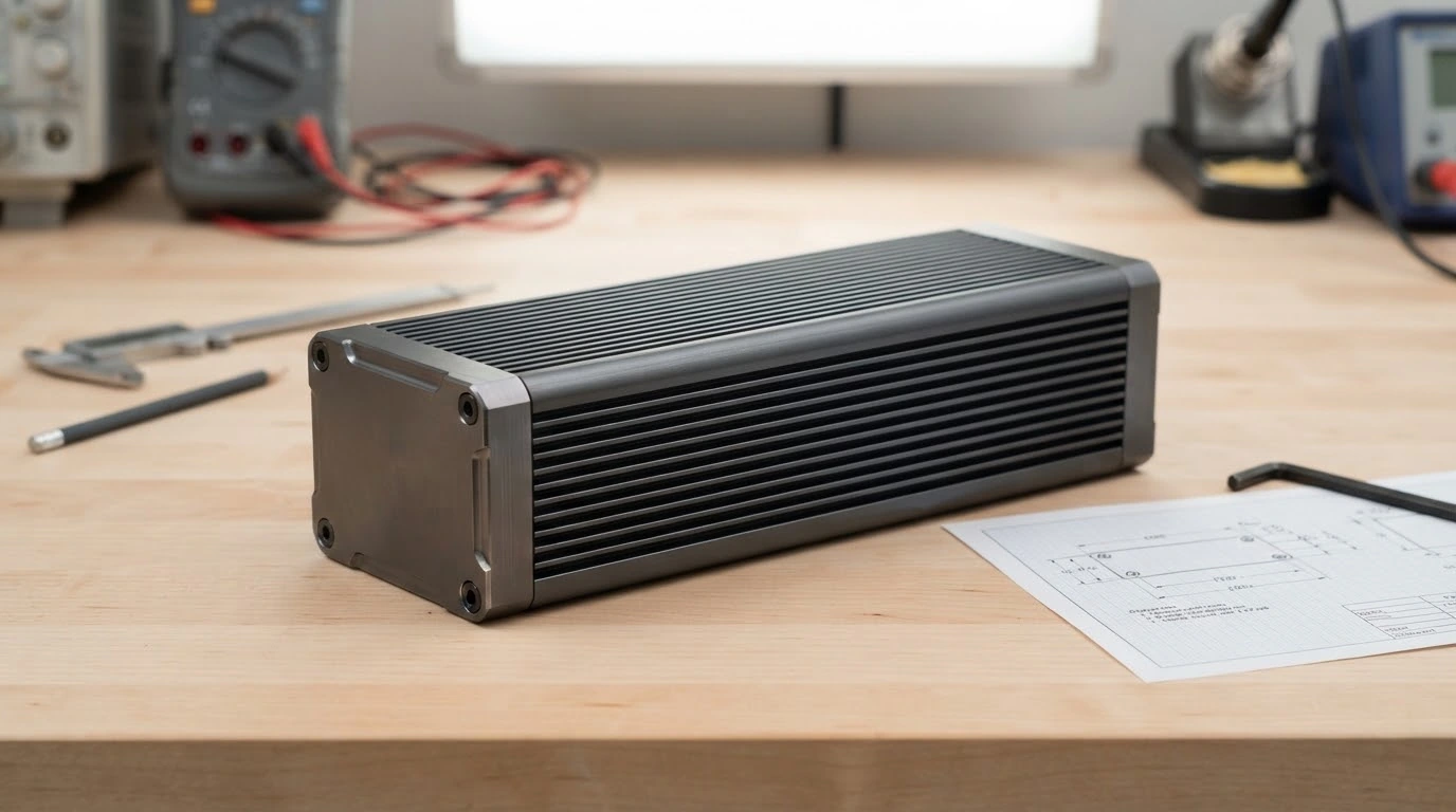
Custom Heat Sink Enclosures. Built Around Your Electronics
Turn the enclosure into a controlled thermal path. morton engineers finned aluminum housings around your PCB, heat sources and installation conditions—from first prototype to repeat production.
One Enclosure. A Direct Path for Heat
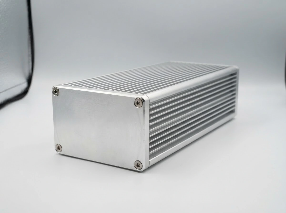
A heat sink enclosure combines structural protection with heat dissipation, moving heat from internal components through a defined interface into the finned housing.
A housing that dissipates heat
Integrated external fins add surface area while the aluminum body protects and locates the electronics.
A defined internal connection
Machined lands, spreaders and selected thermal pads connect heat-generating components to the enclosure wall.
Built for the complete assembly
PCB supports, end plates, interfaces and mounting features are coordinated around your installation.
Solve the Problems Behind Fanless Design
A coordinated housing design helps you manage temperature, installation and service needs without adding unnecessary assembly complexity.
Keep heat moving
Match the contact area, wall thickness and fin layout to the actual heat sources, ambient temperature and mounting orientation.
Reduce mechanical handoffs
Bring PCB location, fasteners, connector access and thermal interfaces into the same drawing review.
Support cleaner operation
A validated fanless design removes the fan from the enclosure assembly and reduces dependence on airflow through the electronics.
Resolve thermal and mechanical constraints in one engineering review.
Talk Through My ConstraintsEngineer Every Link in the Thermal Path
The external fins only work when heat can reach them. We review the complete connection from the component to the surrounding air.
Heat source
Define continuous and peak power, source footprints and allowable component temperatures.
Thermal interface
Select pad thickness, compression and contact pressure around the real assembly gap.
Aluminum housing
Review contact lands, spreading distance and wall thickness to move heat into the enclosure.
Ambient air
Check fin spacing, orientation and free clearance in the installed environment.
Validation inputs: heat-source layout • ambient temperature • installation orientation • surface temperature limits
A useful thermal recommendation starts with defined operating conditions.
Share My Thermal InputsFin Geometry That Fits the Installation
Fin height, spacing and direction are designed together with available clearance so the enclosure can reject heat in its real operating position.
Make room for convection
Provide an open air path around the fins; wall mounting and nearby equipment can change the available convection.
Balance surface area and spacing
More fins do not automatically mean better cooling. Geometry must allow air movement and remain manufacturable.
Validate the installed orientation
Check vertical, horizontal or constrained mounting positions with the intended ambient and heat-source configuration.
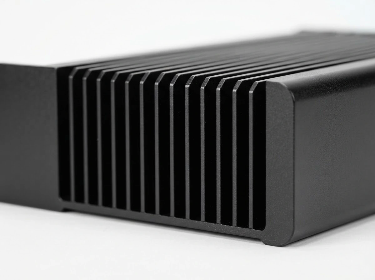
Show us the mounting position and the clearance around your enclosure.
Optimize My Fin LayoutThe Right Material. The Right Manufacturing Route
We choose the enclosure construction around thermal conductivity, structural features, tooling investment and the expected production volume.
6063 aluminum extrusion
Continuous fins and internal profiles support repeatable cross sections. Secondary machining adds the interfaces your assembly needs.
6061 machined construction
Machined plates and contact features support precision prototypes, complex mounting details and structural requirements.
Die-cast aluminum options
Integrated features can simplify suitable production designs. Alloy, tooling and secondary thermal-interface machining are reviewed together.
Choose the manufacturing route around your geometry and annual demand.
Compare Manufacturing OptionsPractical Dimensions. Defined Interfaces
Use these manufacturing ranges to start the discussion, then define the final enclosure around your approved drawing and assembly requirements.
| Typical enclosure envelope | 100–500 × 100–600 × 30–200 mm |
|---|---|
| Typical wall thickness | 2–6 mm |
| Construction materials | 6063 extrusion, 6061 plate or selected cast aluminum |
| Local machined dimensions | Typically ±0.05–0.10 mm within a 100 mm span |
| Critical contact features | ±0.02–0.05 mm where agreed on the drawing |
| Finish options | Clear or black anodizing, conversion coating and powder coating |
Start with the assembly envelope
Reserve space for PCB supports, connectors, the thermal interface and the sealing joint.
Define the acceptance condition
Dimensions and coating thickness are checked in the final specified condition. Overall tolerances depend on size, process and fixturing.
Send a STEP model or dimensioned drawing for a focused DFM review.
Review My Drawing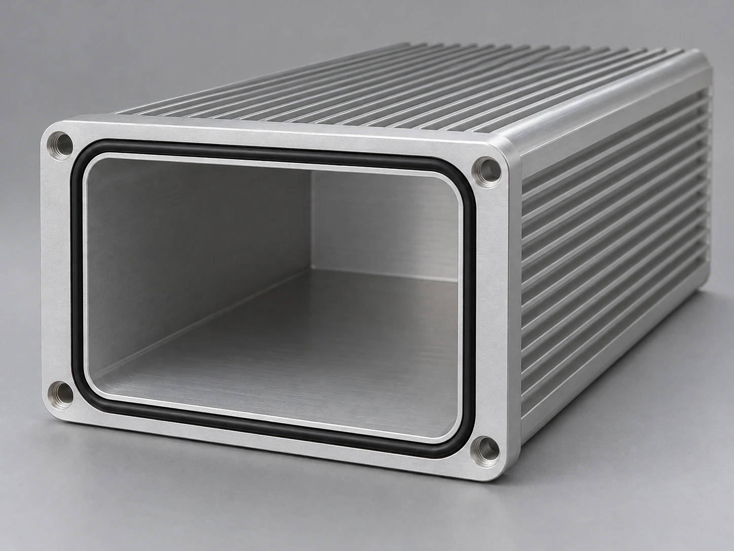
Protection, Grounding and Heat Transfer—Designed Together
Sealing joints and surface finishes must work with the thermal interface and electrical bonding features, rather than compete with them.
Controlled sealing geometry
Specify gasket grooves, joint flatness, fastener spacing and connector sealing around the intended environment.
Deliberate grounding contacts
Preserve or mask defined bonding points where insulating surface treatments would interrupt electrical contact.
Validation at assembly level
Confirm ingress protection, bonding continuity and thermal performance on the intended assembled configuration.
Bring environmental and grounding requirements into the enclosure review early.
Discuss Protection RequirementsCustom Features That Simplify Final Assembly
We integrate the details that make an enclosure fit your electronics, installation method and production line.
PCB location
Board slots, standoffs and support surfaces matched to the board outline and assembly sequence.
Thermal contact lands
Machined pads and spreader interfaces positioned around component heights and load limits.
Connector access
Cutouts, thread features and panel interfaces coordinated with the specified connectors.
Mounting interfaces
Wall brackets, base feet or DIN-rail interfaces reviewed with the installed orientation.
Surface finishing
Color and coating choices with defined masking for contacts, threads and sealing faces.
Identification and packing
Laser marking, part numbers and protective packaging linked to the approved revision.
Combine the features you need into one controlled enclosure drawing.
Build My Feature ChecklistBuilt for Electronics That Work Beyond the Desk
Custom heat sink enclosures support industrial systems where packaging, heat dissipation and dependable installation must work together.
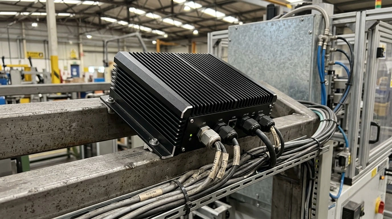
Industrial edge computing
Finned housings for embedded computers operating near machinery, with connector access and service clearance planned in.
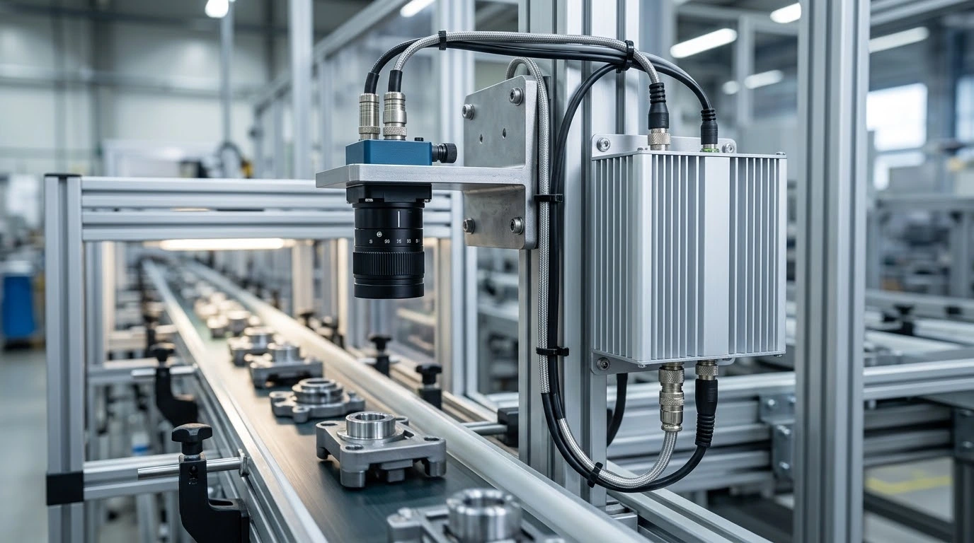
Machine vision and control
Thermal paths and mounting features around processing boards in compact automation equipment.
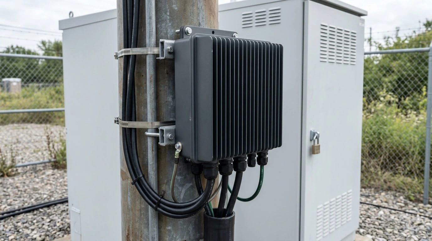
Outdoor communications
Sealing and fin orientation reviewed with ambient conditions, installation exposure and connector interfaces.
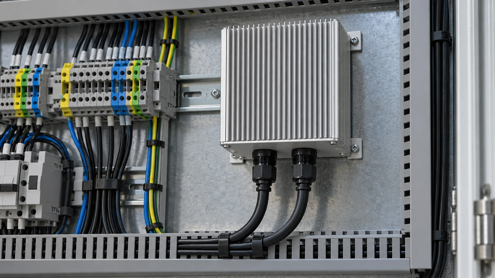
Power and energy controls
Enclosures for control electronics near power-conversion equipment, with defined heat sources and grounding contacts.
Tell us where the enclosure will operate and how it will be installed.
Discuss My ApplicationFrom Your Heat Map to a Validated Enclosure
A staged engineering process keeps thermal decisions, mechanical details and production requirements aligned before you release the design.
Collect CAD, source power, ambient temperature, orientation and the required production volume.
Review the heat path, interfaces, fin geometry and DFM; use thermal analysis where the design requires it.
Build prototypes and evaluate temperature rise, assembly fit and the agreed environmental requirements.
Approve drawings, sample evidence and the control plan before pilot builds and repeat production.
Bring your engineering and purchasing teams into the same project review.
Start an Engineering ReviewQuality You Can Check Against the Drawing
Inspection and traceability focus on the features that control assembly fit, thermal contact and repeatable enclosure performance.
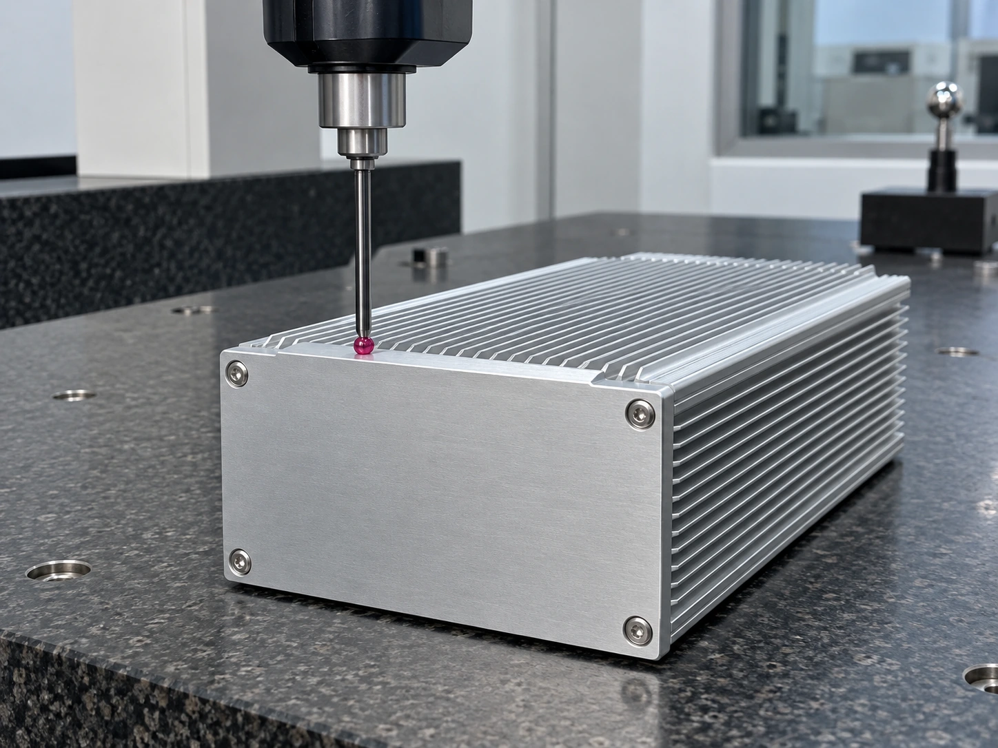
Interface inspection
Check critical dimensions, contact surfaces, threads and sealing features using the agreed inspection plan.
Assembly and thermal checks
Verify the approved configuration, thermal-interface assembly and defined temperature test conditions.
Traceable production records
Link material batches, work orders and inspection records. Traceability records are retained for five years.
Define the critical characteristics before the first article is produced.
Plan My Inspection RequirementsA Supply Plan That Follows Your Product Lifecycle
Keep the approved enclosure configuration consistent as your project moves from engineering samples to scheduled production orders.
Approve the reference
Use an agreed drawing revision and approved sample as the basis for repeat enclosure supply.
Control the changes
Review material, finishing, tooling and process changes before they affect your released configuration.
Coordinate the releases
Plan batch quantities, protective packaging and shipment timing around your production forecast.
Share your sample target and annual demand to build a realistic supply plan.
Discuss Samples and SupplyHeat Sink Enclosure Questions, Answered
The most useful answers depend on your complete assembly. These are the points we clarify at the start of a project.
How much heat can a fanless enclosure dissipate?
There is no single wattage rating for every installation. Heat-source size, ambient temperature, fin geometry, orientation and allowable temperatures determine the enclosure design. We review those conditions and validate the selected assembly.
Can you work from our PCB and STEP model?
Yes. PCB outlines, component heights, mounting locations and connector geometry help us define the thermal interfaces and enclosure features before the drawing is released.
Which material should we choose?
6063 extrusion suits repeatable finned profiles, while 6061 machined construction supports precision features and prototype work. Cast aluminum can suit integrated production geometries after alloy and tooling review.
Does a sealed enclosure still dissipate heat?
Yes. Heat can conduct through the metal housing to external fins without exchanging internal air. The internal thermal connection and external convection conditions still need to be designed and tested.
Can the enclosure meet an IP requirement?
We can design the sealing features around a specified target. The final rating depends on the complete joint, gasket, connectors and assembly, and is confirmed through the agreed enclosure test.
What should we send for an initial review?
Send the available CAD or drawing, heat-source layout, power, ambient range, mounting orientation, environmental requirements and expected annual quantity. We can then identify the next design and quotation inputs.
Have a project-specific question? Put it directly to our engineering team.
Ask About My Enclosure
Let’s Build the Enclosure Around Your Requirements
Share your thermal and mechanical requirements. We will acknowledge your inquiry and confirm the next step within one working day.
Tell Us About Your Enclosure
A few project details help us prepare a useful first response.