

Keep charging power thermally stable
Custom heat sinks and liquid cold plates for EV charger power modules, rectifiers and cabinet electronics—engineered around your real operating conditions.
More power. Less room for heat
Sustained losses, warm inlet air and restricted airflow can overheat compact charger power modules. Derating or protective shutdowns can then reduce delivered charging power or interrupt a session.
Concentrated power losses
Rectifier and DC/DC switching stages concentrate heat at semiconductor interfaces. A local hot spot can set the limit for the entire power module.
Hotter inlet conditions
Solar exposure, recirculated air and warm equipment rooms shrink the temperature difference available for cooling.
Restricted air paths
Filters, dense fins and tight packaging raise resistance. Free-air fan ratings do not describe the airflow through an installed heat sink.
Repeated charging cycles
Load changes and thermal expansion stress contact interfaces, joints and seals over the equipment lifecycle.
Follow the heat. Find the bottleneck
A lower component temperature starts with the complete path from the device interface to the surrounding air or coolant.
We compare the whole thermal path so that improving one interface does not hide a restriction elsewhere.
The right cooling route for every power stage
Select the structure around heat-source density, available space, flow conditions and the way your charging equipment is assembled.
Extruded Heat Sinks
For modular rectifiers and cabinet power electronicsCNC-finished mounting faces and defined fin channels support repeatable installation and cost-effective volume supply.
Skived Fin Heat Sinks
For compact, concentrated heat sourcesIntegral copper or aluminum fins add surface area where the available fan pressure can support the fin density.
Heat Pipe Assemblies
For offset hot spots and restricted mounting zonesTransfer heat to an accessible fin area, with orientation and working temperature verified.
Vacuum Brazed Cold Plates
For distributed power-module footprintsInternal fins and multiple flow paths support compact heat rejection with a defined flow and pressure-drop target.
Friction Stir Welded Cold Plates
For larger liquid-cooled power stagesMachined channels and a welded cover integrate the coolant path with mounting and port requirements.
Hybrid Cooling Assemblies
For liquid-cooled main stages with air-cooled auxiliary devicesCoordinate both paths in one mechanical package and define their separate operating limits.
Designed around where your chargers operate
The installation environment changes the cooling brief—even when the power electronics share the same platform.
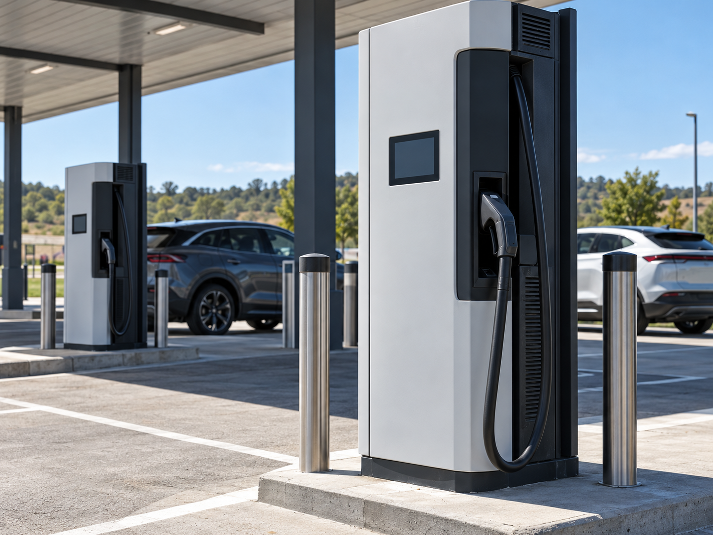
Highway DC Fast Charging
Outdoor exposure, warm inlet air and repeated sessions call for controlled airflow, serviceable fin paths and validated temperature margin.

Fleet & Depot Charging
Long charging windows and grouped cabinets make sustained duty, coolant distribution and maintainable interfaces central to the design.
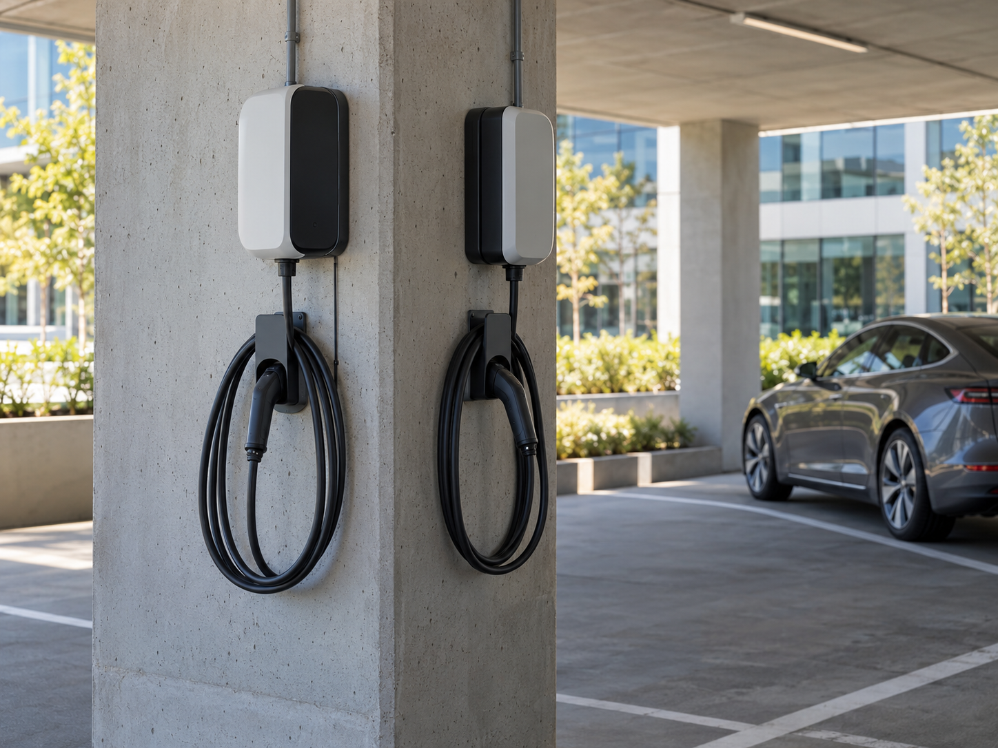
Urban & Workplace Charging
Compact housings place pressure on space and acoustic targets. Match conduction paths, air-cooled surfaces and electronics clearances early.
Make your installation environment part of the cooling decision.
Discuss Your ApplicationChoose with operating data, not a power label
Use the same heat load, source layout and temperature target to compare the practical trade-offs of air cooling and liquid cooling.
| Decision input | Air cooling | Liquid cooling |
|---|---|---|
| Available temperature margin | Air cooling Ambient and inlet-air temperature define the available margin. | Liquid cooling Inlet-coolant temperature and the device interface define the available margin. |
| Flow delivery | Air cooling Check the installed fan operating point and airflow through the fin channels. | Liquid cooling Check the pump operating point, branch balance and cold-plate pressure drop. |
| Packaging | Air cooling Reserve fin volume, ducting and filter access. | Liquid cooling Reserve ports, hose bend radius, drainage and service clearances. |
| Reliability controls | Air cooling Manage dust loading, vibration and fin or joint integrity. | Liquid cooling Manage cleanliness, coolant compatibility, leak tightness and pressure cycling. |
| Best starting inputs | Air cooling Loss map, inlet temperature, fan curve and available envelope. | Liquid cooling Loss map, coolant specification, inlet temperature, flow and pressure limits. |
Measurement basis: Base hot-spot thermal resistance = (base hot-spot temperature − inlet medium temperature) / effective heat load. Device junction and TIM temperature rises are evaluated separately.
Send the boundaries that determine your cooling architecture.
Compare Your Cooling Options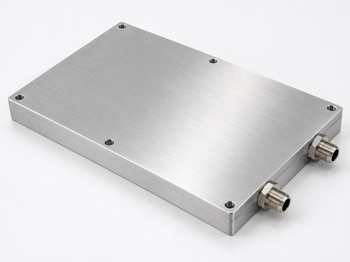
Small interface details. Lasting thermal performance
Flatness, mounting load and coolant compatibility connect a promising design to a stable assembled product.
Resolve the interfaces before they become assembly issues.
Review Your Mechanical InterfaceProve the design before you scale it
A useful validation plan connects the agreed operating conditions to measurements, acceptance criteria and traceable production records.
Thermal performance
Record heat-source dimensions, losses, inlet conditions, installed flow, sensor positions and steady-state criteria. Compare the base hot spot to the agreed limit.
Flow & pressure drop
Measure pressure drop at the component boundary and verify flow distribution at the selected fan or pump operating point.
Leak & pressure integrity
For liquid-cooled parts, define proof pressure and leak acceptance by the approved design. Preserve individual test records with the component batch.
Dimensions & assembly
Check contact faces, port locations, threads, mounting alignment and the assembled TIM condition against the frozen drawing.
Define acceptance criteria your engineering and quality teams can share.
Plan Your ValidationFrom your first brief to a controlled production part
One project team connects thermal requirements, manufacturability, samples and the documents needed for repeat orders.
A clear first brief makes the next engineering decision easier.
Start Your Project Review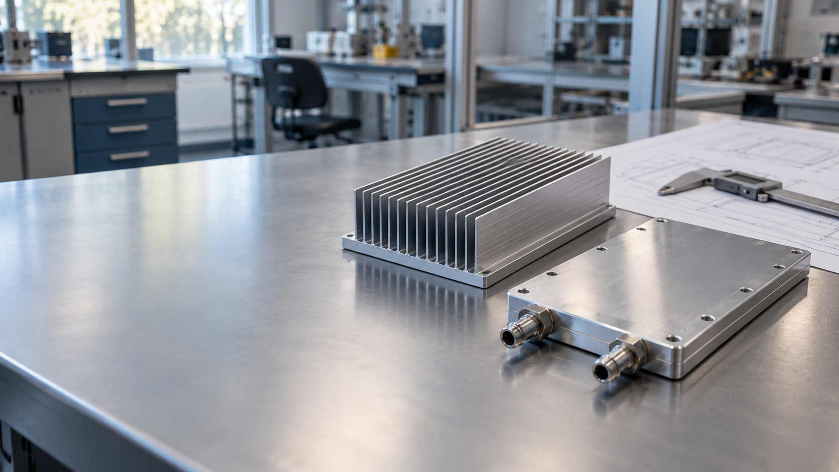
Bring us your charging thermal challenge
Share your power-stage requirements. We will review the cooling route, key interfaces and the next step toward a manufacturable component.