
Choose an OSFP riding heat sink by matching the module variant, host cage, thermal contact and installed cooling conditions. A familiar optical connector does not establish mechanical compatibility. Specify the module and cage drawings together when evaluating an OSFP riding heat sink, then qualify the assembled hardware before releasing a production order.
1. What is an OSFP riding heat sink assembly?
An OSFP riding heat sink assembly uses host-side cooling hardware to contact the designated thermal surface of a pluggable module. For the OSFP-RHS variant, the module has no integrated heat sink and relies on the matching host arrangement. The sink stays with the host while the module is replaceable. Define the complete assembly before comparing a supplier’s fin design or thermal rating.
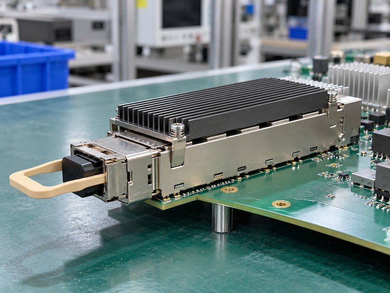
Which drawing defines the product you need?
Identify the module, cage, connector, retention hardware and cooling device by their actual revisions. Keep the permitted module envelope and contact area with those records. The OSFP name covers several mechanical and electrical configurations, so a broad catalog description cannot establish the required mating condition. A heat sink proposal becomes reviewable when the supplier can show where it contacts the module, how it is retained and what remains clear during replacement.
- Identify the exact module and host variants.
- Define the retained cooling components.
- Keep thermal and mechanical acceptance conditions together.
| Assembly element | Required definition | Review input |
|---|---|---|
| Module | Variant and thermal contact area | Released module drawing |
| Cage | Mating and retention features | Host assembly drawing |
| Cooling hardware | Contact, support and heat rejection | Qualified configuration |
Use this assembly identity throughout the quotation and sample approval process.
2. Does every OSFP riding heat sink fit a finned module?
An OSFP riding heat sink does not automatically fit every module sold under the OSFP name. Integrated-heat-sink modules and OSFP-RHS modules have different thermal and mechanical arrangements. A description such as flat top can also be ambiguous without a drawing. Review the specified variant rather than deciding from a front connector photograph, a data-rate label or the apparent similarity of two metal housings.
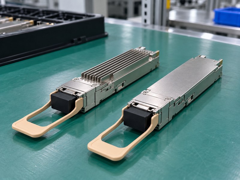
What difference does the RHS designation make?
The OSFP specification, Revision 5.22, defines OSFP-RHS as a module without an integrated sink and with a nominal 9.5 mm body height inside the cage. It also changes the positive stop and cage interface relative to conventional OSFP. Those details explain why a matching electrical connector or board layout cannot establish cage interchangeability. Confirm both the module and the platform’s supported configuration before selecting replacement cooling hardware.
- Use the manufacturer’s exact variant designation.
- Check host support for the proposed module.
- Separate connector similarity from mechanical compatibility.
| Description | Cooling arrangement to verify | Purchasing check |
|---|---|---|
| Integrated heat sink | Cooling structure on the module | Approved host configuration |
| OSFP-RHS | Designated host-side contact | Matching RHS cage |
| Informal flat-top label | Meaning varies with description | Obtain the drawing |
Resolve the variant before using a supplier’s sample as a production reference.
3. How should an OSFP riding heat sink cage be checked?
Check an OSFP riding heat sink cage against the actual module’s stops, latch features, contact opening and surrounding keepouts. The module must reach its intended seated position without forcing the wrong mating arrangement. Review the host assembly as well as the loose cage. Board position, mounting variation and neighboring hardware can change the available space even when the individual cage drawing is correct.
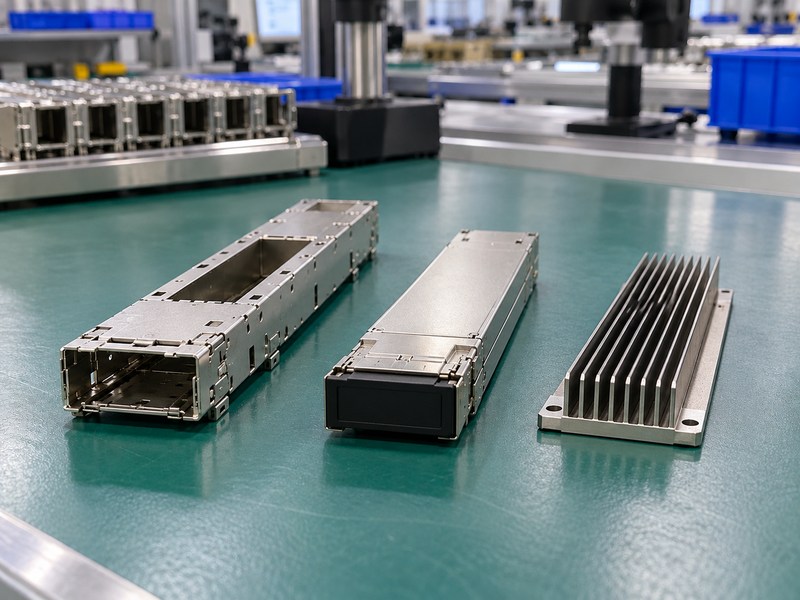
What should a mating trial demonstrate?
Use representative modules and the intended retention hardware to check the full insertion and removal stroke. Confirm the latch engages, the contact feature reaches the correct surface and the release mechanism remains accessible. Review the limiting dimensions instead of approving only a nominal sample. If a module stops short, investigate the mating geometry; increasing insertion effort cannot establish compatibility and may hide the interference that the trial should identify.
- Check the complete travel path.
- Inspect the seated and released positions.
- Track the module and cage sample revisions.
| Cage feature | Review question | Evidence |
|---|---|---|
| Positive stop | Is this the correct mating variant? | Drawing and fit review |
| Top opening | Can cooling hardware reach the contact area? | Sectioned assembly review |
| Latch and release | Can the module be serviced? | Mating trial |
Retain the approved mating combination rather than treating the cage as an interchangeable enclosure.
4. Which OSFP riding heat sink contact surfaces need inspection?
An OSFP riding heat sink needs inspection of the mating pedestal and the module’s designated thermal surface. Flatness, texture, coatings and edge damage can affect their contact differently. Define which requirement applies to which surface before choosing the measurement method. A module-side standard requirement does not automatically specify every host-side pedestal feature, so the host drawing still needs its own reviewed interface limits.
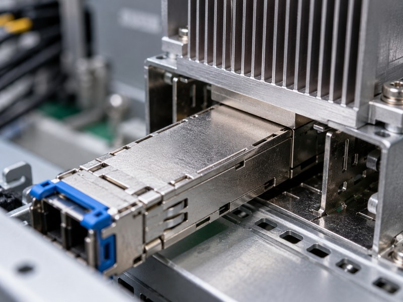
Which module-side limits does the specification provide?
Table 12-2 in OSFP Revision 5.22 specifies the module’s thermally conductive area according to its maximum power, as summarized below. These values describe that designated module area, not every face on the heat sink. Check the applicable drawing and revision before using them as acceptance criteria. Inspect the final manufactured surfaces and their contact alignment instead of assuming that a bright finish or a roughness report establishes the whole interface.
- Identify the specified contact footprint.
- Separate flatness from surface texture.
- Inspect after coating and final cleaning.
| OSFP-RHS maximum power | Module surface flatness, or better | Module surface roughness, or better |
|---|---|---|
| Up to 5 W | 0.15 mm | Ra 3.2 µm |
| Above 5 W through 14 W | 0.075 mm | Ra 1.6 µm |
| Above 14 W | 0.05 mm | Ra 0.8 µm |
Keep the module limits and the separately specified pedestal acceptance criteria on the inspection plan.
5. How much force should an OSFP riding heat sink apply?
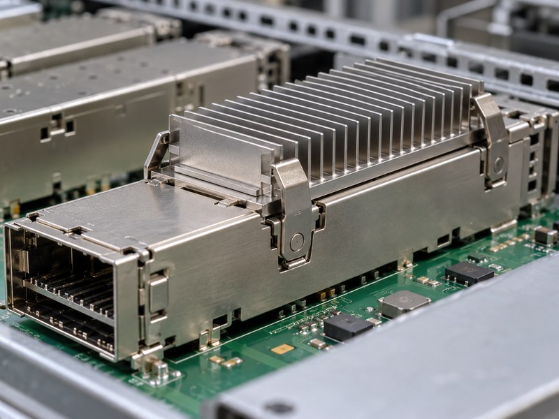
An OSFP riding heat sink should apply the approved load for its actual cage and module combination across the permitted dimensional variation. The load path must pass through features designed to carry it. Check contact displacement, clip behavior and host support together. A spring’s free height or a fastener torque cannot establish the module contact force without the rest of the assembly definition.
Does the standard’s maximum force define the target?
No. Section 12.8 of OSFP Revision 5.22 gives a 50 N maximum downward force for an OSFP-RHS cage; that ceiling is not a recommended operating target. The chosen assembly must also meet its component-specific mechanical and thermal requirements. Verify the retention system at its limiting installed positions. Do not transfer this ceiling to a different OSFP arrangement or another pluggable family, which may have different requirements.
- Specify the required load-displacement behavior.
- Check the contact condition across tolerances.
- Inspect clips for permanent deformation after testing.
| Force-related input | What it establishes | Required review |
|---|---|---|
| Applicable maximum | Upper design boundary | Correct specification and variant |
| Installed spring condition | Actual load range | Mechanical verification |
| Contact result | Thermal behavior at that load | Matched assembly test |
Approve the actual operating range rather than selecting a spring solely from the maximum allowed force.
6. How should OSFP riding heat sink airflow be evaluated?
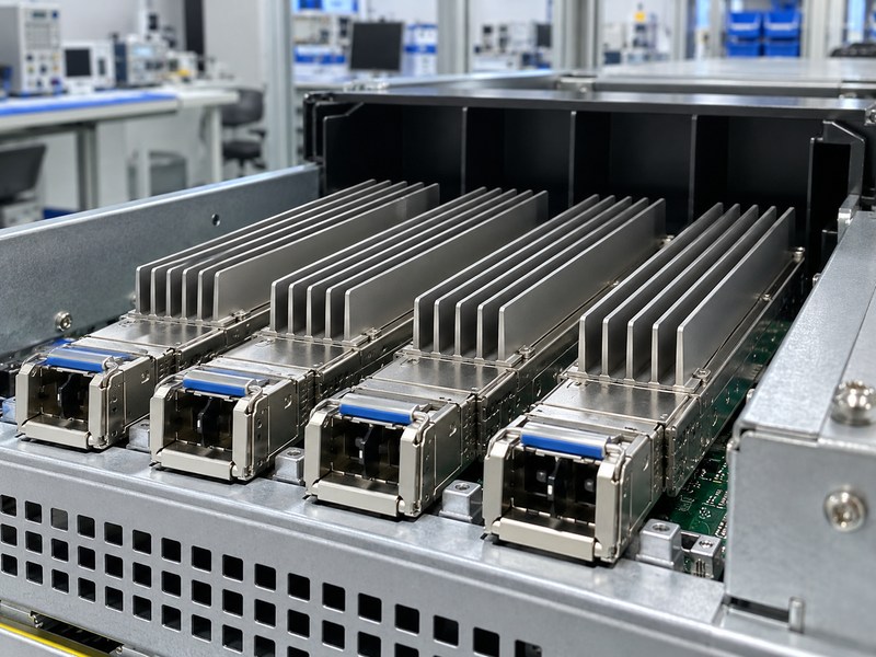
Evaluate OSFP riding heat sink airflow in the intended port row and enclosure, including the local air temperature and available fan pressure. The heat sink channels may compete with bypass paths around the cages. Nearby devices can also warm the air before it reaches the optical modules. Test the populated arrangement with its released ducts and covers instead of assigning an open-bench rating directly to the final product.
Can an integrated-module airflow requirement be reused directly?
Check its applicability before doing so. OSFP-RHS uses a different cooling architecture, and the specification distinguishes the airflow requirement associated with the conventional integrated-sink arrangement. The host still needs a thermal and pressure-flow assessment appropriate to its own cooling device. Record the reference locations for inlet air and case temperature, then evaluate realistic neighboring port populations and operating states rather than treating one empty-cage test as the complete system condition.
- Confirm which specification sections apply.
- Inspect fin direction and channel clearance.
- Measure the relevant installed air condition.
| Airflow condition | Review input | Possible mismatch |
|---|---|---|
| Local inlet | Temperature near the optical port | Room air temperature |
| Host flow path | Duct and cage configuration | Open-bench flow |
| Port population | Intended neighboring modules | Mostly empty equipment |
Keep the tested enclosure configuration with every thermal result used for approval.
7. Can an OSFP riding heat sink use liquid cooling?
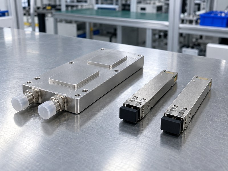
An OSFP riding heat sink architecture can be replaced or supplemented by a separately engineered cooling device when the host design supports it. A flat module surface alone does not establish compatibility with a cold plate. Review the mechanical contact, support, service path and system cooling requirements together. Liquid cooling changes the design boundary; it cannot be specified by adding two fittings to an existing air-cooled sink.
What must remain serviceable around a cold plate?
Confirm how the module can be inserted, latched and removed without disturbing a coolant connection that was not designed for routine service. Review the plate’s support separately from the contact load applied to the module. The design also needs defined fluid, pressure, flow, sealing and leak-test requirements. Where the cage opening changes for another cooling device, include the resulting mechanical support and electromagnetic shielding requirements in the host review.
- Define the plate-to-module contact mechanism.
- Keep plumbing outside the required service path.
- Qualify the complete supported cooling assembly.
| Cooling input | Required definition | Acceptance evidence |
|---|---|---|
| Contact and support | Load path and service movement | Mechanical qualification |
| Fluid circuit | Fluid, flow and pressure conditions | Hydraulic and leak verification |
| Host integration | Cage and shielding requirements | System review |
Approve liquid cooling as a host assembly with its own operating and service requirements.
8. How should OSFP riding heat sink interfaces survive service?
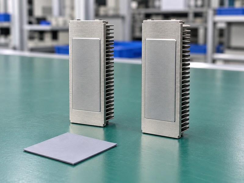
An OSFP riding heat sink interface should maintain its approved thermal and mechanical behavior over the required mating and service exposure. Evaluate the actual module edges, contacting mechanism and surface materials. A low initial resistance does not demonstrate that the interface survives repeated insertion. Keep the durability method and inspection criteria with the selected interface so a material substitution cannot silently change the qualified assembly.
What can happen to a conventional interface pad?
Sliding contact can tear, displace or contaminate a material that works well in a stationary joint. The optical I/O thermal discussion describes this wear problem and alternative contact mechanisms. Test the proposed material in its intended host rather than selecting it only by bulk conductivity. Inspect the same mating surfaces during cycling and repeat the thermal assessment after the required exposure, retaining any failed samples for investigation.
- Record the approved interface material identity.
- Inspect wear and debris at defined intervals.
- Recheck contact after module replacement trials.
| Service evidence | What it can reveal | Follow-up |
|---|---|---|
| Surface inspection | Abrasion or displaced material | Review the sliding path |
| Mating behavior | Load or alignment changes | Investigate the retained assembly |
| Thermal retest | Changed interface performance | Compare with the baseline |
Tie durability approval to the actual mechanism and material combination used in production.
9. How do you validate an OSFP riding heat sink temperature limit?
Validate an OSFP riding heat sink against the module supplier’s defined temperature reference and the host operating conditions. An internal diagnostic reading, a case reference point and a sensor on the sink are different measurements. Establish how the selected method represents the required limit. Record module power, neighboring port population, local air or coolant conditions and the installed interface with the test result.
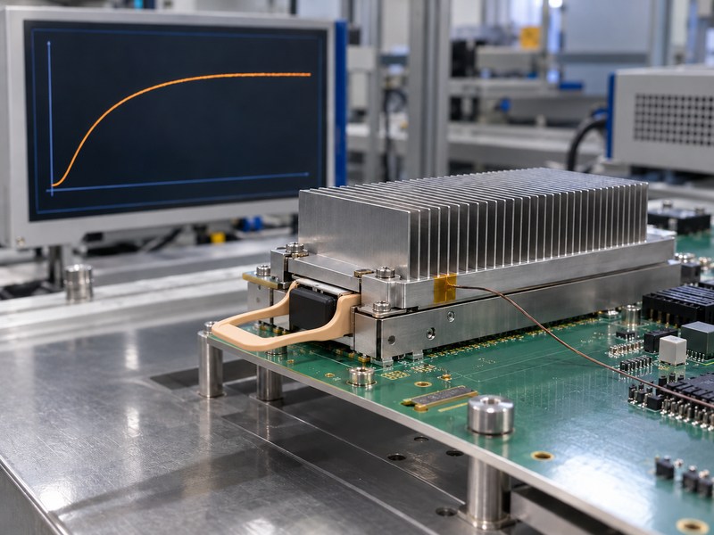
What should a qualification report make reproducible?
Describe the tested hardware revisions, sensor positions, mounting procedure and steady-state criterion. Include relevant operating extremes and uncertainty when judging small temperature differences. If software telemetry is used for acceptance, document its relationship to the required temperature reference instead of assuming they are identical. The pictured stabilization curve is a qualitative illustration, not a measured module rating, and should not be used to infer a power limit or temperature reduction.
- Use the specified measurement location.
- Preserve the tested contact and retention condition.
- Compare prototypes at matched boundary conditions.
| Report item | Required information | Review purpose |
|---|---|---|
| Module and host | Part identities and revisions | Reproduce the assembly |
| Temperature method | Reference and sensor placement | Interpret the limit correctly |
| Boundary conditions | Load, airflow or coolant state | Assess application relevance |
Keep the qualification conditions visible when a supplier presents a thermal performance claim.
10. What should an OSFP riding heat sink supplier deliver?
An OSFP riding heat sink supplier should deliver the agreed hardware, inspection evidence and qualification scope for the specified mating assembly. Request the module and cage interfaces alongside the heat sink drawing. Separate tooling, samples, finishing, retention hardware and testing in the quotation. This lets you compare equivalent offers and identify whether the supplier expects the host team to provide part of the mechanical or thermal verification.
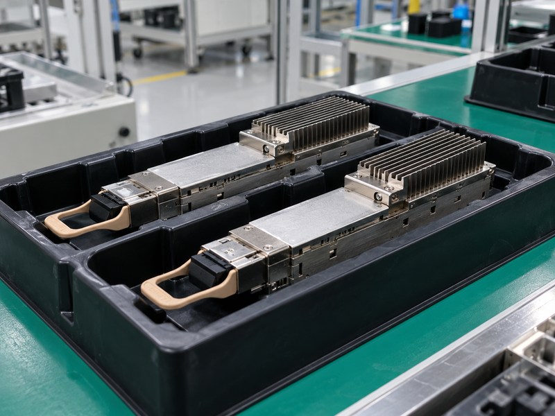
Which changes should trigger another review?
Define notification requirements for changes to the cage, module variant, contact finish, interface material, retention system or cooling arrangement. Keep approved exceptions with the drawing and sample records. Send those interface drawings, operating conditions and service requirements when you contact us. Release production against the approved assembly definition so a similar-looking replacement does not bypass the compatibility and thermal checks completed during qualification.
- Identify every approved mating component.
- Retain inspection and test conditions together.
- Review substitutions before shipment acceptance.
| Delivery record | What it controls | Update trigger |
|---|---|---|
| Released drawings | Mechanical identity | Component or geometry change |
| Interface specification | Surface and retention condition | Finish or material substitution |
| Qualification report | Approved operating boundaries | Load or cooling change |
Accept subsequent batches against these records and investigate differences before changing the release.
Frequently asked questions
Q1: Can I choose an OSFP-RHS module by data rate alone?
No. Check the exact module and supported host configuration, including mechanical, electrical, management and optical requirements. The data-rate label does not establish compatibility.
Q2: What’s the best contact force for OSFP-RHS?
Use the approved range for the actual assembly. The specification’s maximum force is a ceiling and does not define the best operating load for every host.
Q3: How do I know whether a flat-top module is RHS?
Confirm the manufacturer’s variant designation and drawing. Informal appearance labels can refer to different constructions and should not replace the mechanical definition.
Q4: Can a thermal pad solve every contact problem?
No. Verify geometry, load, sliding wear and cleanliness first. The material and contact mechanism need qualification together for the required mating life.
Q5: Does a flat RHS module automatically support a cold plate?
No. The host needs an approved contact and support mechanism, a serviceable module path, and a qualified fluid circuit and cooling assembly.