
Choose a riding heat sink around its host cage, module contact surface, insertion life and installed airflow. A module can latch correctly yet run hot if the contact joint or local air path is poorly controlled. Specify those interfaces together when you develop a riding heat sink for pluggable optical modules.
1. What does a riding heat sink do?
A riding heat sink transfers heat from a pluggable module’s metal housing into a host-side cooling structure. The cage or host retains the sink while the module slides into its operating position beneath it. This arrangement lets the cooling hardware remain with the equipment during a module change. Its performance depends on the complete path from the module housing, through the contact joint, into the sink and surrounding air.
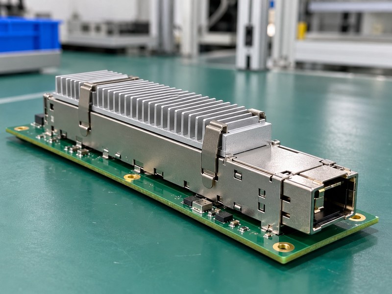
Which parts remain with the host?
Identify the cage, heat sink, retention hardware and any separate cooling support on the host drawing. Then identify the replaceable module and its approved contact area. A module with an integrated heat sink uses a different mechanical arrangement, even if the front connector looks familiar. Do not treat these configurations as interchangeable without checking the module, cage and platform specifications, including any stops or keepout features that control insertion.
- Define the retained and replaceable components.
- Identify the intended module contact area.
- Keep the host drawing with the thermal specification.
| Component | Principal role | Approval input |
|---|---|---|
| Module housing | Conduct heat toward the interface | Module specification |
| Cage and retainer | Locate and hold the assembly | Mechanical drawing |
| Heat sink | Spread and reject heat | Installed thermal evidence |
Start selection with this assembly definition so a quotation describes the hardware you need.
2. How does the riding heat sink contact the module?
The riding heat sink normally contacts a designated module surface through a pedestal or other approved thermal contact feature. That feature must reach the module through the intended cage opening while preserving the module’s insertion path. Heat should not be expected to cross an unspecified clearance or an intervening cage wall. Review the full tolerance stack because contact depends on the relative positions of the module, cage, pedestal and retainer.
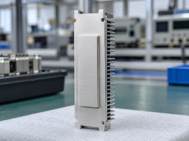
What belongs in the tolerance review?
Include the highest and lowest permitted positions of each mating surface, together with board and cage assembly variation. Confirm that the sink can accommodate the intended displacement without losing contact or overloading the module. Review leading edges and transitions along the sliding path. A pedestal that seats well on one sample can catch an edge or fail to reach another sample if the design was approved only at nominal dimensions.
- Use the specified mechanical datums.
- Check limiting combinations of mating dimensions.
- Confirm clearance through the insertion stroke.
| Feature | Question to resolve | Evidence |
|---|---|---|
| Cage opening | Can the contact feature reach the module? | Sectioned assembly review |
| Pedestal height | Is contact maintained across variation? | Tolerance analysis |
| Leading edge | Can the module pass without damage? | Mating trial |
Approve the stack before increasing spring load to compensate for an unexplained contact problem.
3. How should a riding heat sink be retained?
A riding heat sink should be retained by hardware that maintains the required contact while allowing the specified module movement. Leaf clips, springs and host supports need a defined load path through features designed to carry that load. The retention system must also preserve latch access and module removal. Use the applicable cage and module requirements rather than borrowing a force value from another connector family.
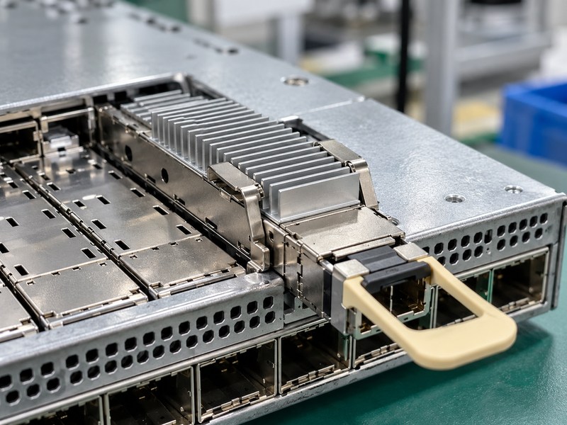
What does a useful retention specification state?
State the permitted load and displacement conditions, the attachment features and how the supplier verifies them. Review clip location so it does not deform delicate fins or force the cage out of alignment. A spring’s free height alone cannot establish the installed contact force. Include manufacturing variation, assembly sequence and the expected service environment when deciding whether a retainer stays within the allowed operating range over its intended life.
- Locate clips on approved load-bearing features.
- Confirm the latch and pull mechanism remain accessible.
- Keep module and cage force limits separate.
| Retention input | What it controls | Verification |
|---|---|---|
| Load versus displacement | Contact through dimensional variation | Defined mechanical test |
| Clip attachment | Position and retention | Assembly inspection |
| Service movement | Insertability and removability | Mating-cycle evaluation |
Resolve the contact and retention requirements together before releasing the clip design.
4. Which surfaces govern riding heat sink contact?
Riding heat sink contact depends on the condition of both mating surfaces, including flatness, texture, coatings and local damage. A shiny pedestal can still have poor contact if it is bowed or misaligned with the module housing. Define each surface against the correct drawing and standard revision. Inspect the final manufactured condition rather than relying on a machining report produced before plating, cleaning or another finishing operation.
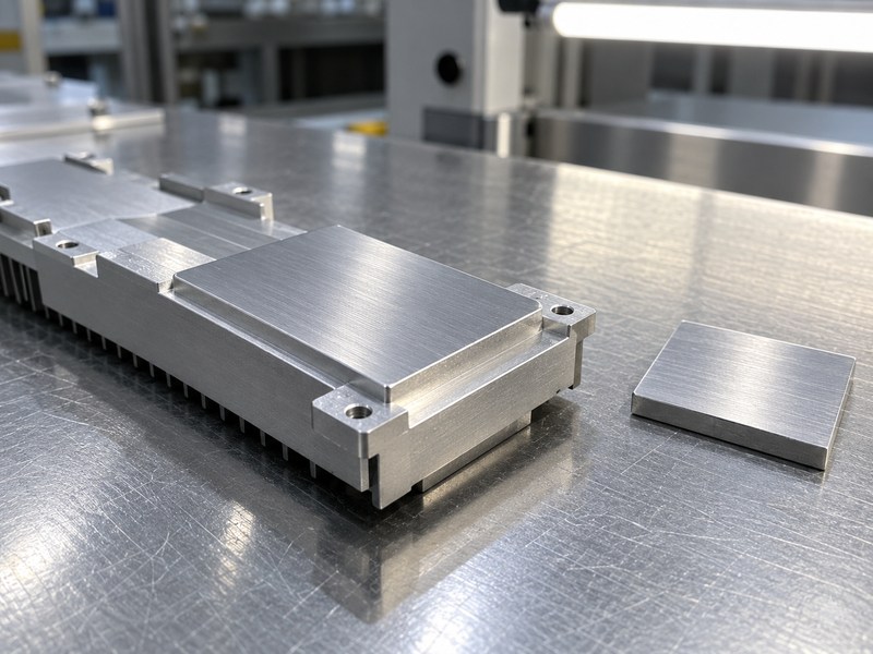
What should the inspection method distinguish?
Separate geometric flatness from roughness and appearance. Those characteristics describe different surface properties and need suitable inspection methods. Also examine edges, burrs and handling damage that could alter the sliding interface. Keep measuring support and force under control so the inspection does not bend the component while evaluating it. If one surface fails, determine which manufacturing step caused the change before treating additional clip force as the corrective action.
- Identify the actual contact footprint.
- Inspect after the complete finishing sequence.
- Record defects separately from nominal dimensions.
| Characteristic | What it describes | Common inspection error |
|---|---|---|
| Flatness | Overall geometric form | Judging it by surface shine |
| Roughness | Local surface texture | Substituting a photograph |
| Edge condition | Entry and sliding features | Checking only the center |
Keep the inspection record tied to the same drawing revision used for the mating trial.
5. Can a riding heat sink use a thermal interface material?
A riding heat sink can use a thermal interface material only when the material and contacting mechanism are qualified for the application. A pad that works under a stationary processor may be damaged by the edges of a sliding optical module. Check how contact develops during insertion and releases during extraction. Include contamination, friction and repeated handling in the review alongside the installed thermal resistance.
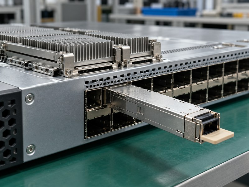
Why is a stationary pad test insufficient?
It does not reproduce the sliding path or the damage that can occur during a module change. The I/O thermal interface discussion identifies abrasion during module insertion as a limitation of conventional interface materials. Evaluate the proposed material in the actual mechanism, including worn and serviced conditions. If contact is delayed by a different retention mechanism, qualify that mechanism rather than assuming it behaves like a conventional sliding interface.
- Check the complete mating and removal stroke.
- Inspect for tearing, displacement and residue.
- Repeat thermal checks after the required cycling.
| Interface condition | Qualification concern | Evidence |
|---|---|---|
| Initial assembly | Coverage and contact | Baseline inspection |
| Repeated mating | Wear and displacement | Cycle inspection |
| Service exposure | Stability and contamination | Agreed environmental review |
Select the interface from thermal and durability evidence for the intended assembly.
6. How does local airflow affect a riding heat sink?
Local airflow affects a riding heat sink through the air temperature and flow actually reaching its channels. A chassis fan rating does not establish either condition at the optical port. Nearby components may preheat the air, and gaps around the sink may let useful flow bypass it. Evaluate the populated enclosure with the intended ducts, covers and neighboring hardware in place before accepting an open-bench cooling result.
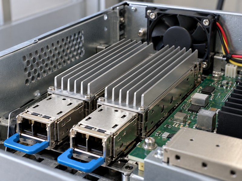
Which operating conditions should your test reproduce?
Include the expected population of neighboring ports, relevant system power states and the permitted maintenance condition. Check both thermal performance and pressure-flow behavior where airflow is constrained. A local baffle can change how air divides between competing paths, so it also changes the conditions represented by a prior test. Record where inlet temperature and flow were measured rather than substituting room temperature or a fan’s free-air specification.
- Check upstream heating at the optical port.
- Inspect bypass paths around the fin bank.
- Test with the released enclosure configuration.
| Airflow input | Relevant condition | Otherwise you may measure |
|---|---|---|
| Inlet temperature | Air arriving at the port | Room conditions |
| Flow distribution | Flow through the sink | Total chassis flow |
| Port population | Intended neighboring modules | An unrepresentative empty chassis |
Keep these conditions with the thermal result so the comparison remains useful after a system change.
7. Which riding heat sink fin design should you choose?
Choose a riding heat sink fin design that meets the installed thermal requirement within its mechanical and airflow limits. Extruded, machined and assembled-fin constructions offer different geometry and manufacturing options. More surface area can also create more flow resistance, so fin count alone cannot select the better design. Review base spreading and contact performance before attributing every temperature difference to the fins.
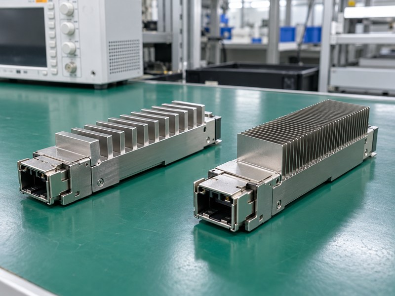
When should you review the base construction?
Review it when heat enters through a small footprint or when a long sink develops a substantial temperature gradient. A different base thickness, material or spreading structure may be worth evaluating, but each option needs evidence at the same operating conditions. A vapor chamber introduces its own manufacturing and mechanical requirements; its presence does not establish a universal performance gain. Compare complete proposals, including attachment, mass, available height and recurring production cost.
- Match fin direction to the intended flow path.
- Compare pressure-flow behavior with thermal results.
- Include retention and clearance in the geometry review.
| Design choice | Potential reason to evaluate it | Required comparison |
|---|---|---|
| Extruded profile | Repeatable continuous section | Feasible geometry and thermal data |
| Assembled fins | Alternative fin density | Installed airflow and integrity |
| Enhanced base | Heat-spreading requirement | Same-load temperature evidence |
Approve a construction because its measured assembly performance meets the requirement.
8. How do you qualify riding heat sink insertion wear?
Qualify riding heat sink insertion wear by cycling the actual module and host combination under an agreed procedure. Inspect the contact surface, retention hardware and module housing at defined intervals. Thermal performance and mating behavior should remain within the acceptance limits after the required cycling. The test should identify the module variants and sample conditions used, because one nominal module cannot represent every permitted tolerance or service condition.
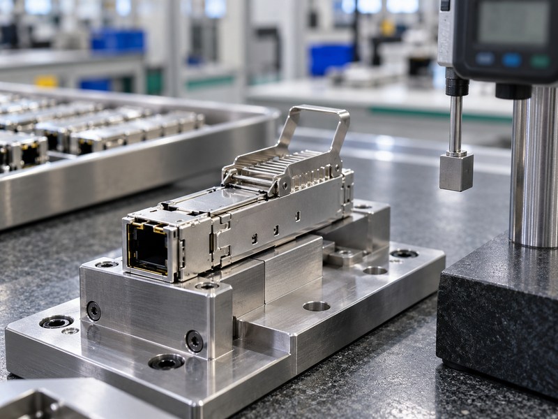
What should you record besides a cycle count?
Record insertion and extraction behavior, surface changes, debris and any shift in the retention condition. Use the applicable supplier requirements to define alignment and handling conditions instead of introducing uncontrolled side loads. If a failure appears, retain the affected mating pair for investigation. Replacing a damaged sample midway through a test without recording the change can hide the mechanism that the qualification was meant to expose.
- Inspect the same defined contact locations.
- Track module and host sample identity.
- Recheck thermal behavior after the required exposure.
| Wear evidence | Possible implication | Follow-up |
|---|---|---|
| Scratched contact land | Changed sliding condition | Review edges and surface treatment |
| Loose particles | Debris generation | Identify source and acceptance impact |
| Changed mating force | Retention or alignment change | Mechanical investigation |
Retain the results with the released assembly configuration and required change-control conditions.
9. How should riding heat sink thermal performance be tested?
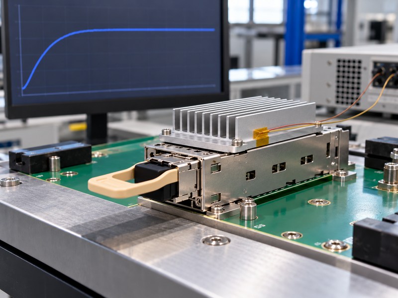
Test riding heat sink thermal performance using defined heat input, local air conditions and temperature measurement locations. Distinguish the module’s specified case reference from an internal component temperature or a sensor placed on the sink. A simple thermal budget can guide selection, but the model must describe the heat paths it includes. Account for parallel conduction through the cage or board where those paths affect the result.
What does an initial thermal budget tell you?
As a hypothetical example, a 20 W heat load with a 20 K case-to-local-air temperature allowance gives an effective assembly budget of 1.0 K/W. That calculation does not supply a heat sink rating; the allocation still needs contact, spreading and convection contributions for the modeled path. The faceplate thermal discussion explains why contact resistance and local air conditions need separate attention. The pictured trace is qualitative and contains no measured module values.
- Define the temperature reference and sensor method.
- Document the steady-state acceptance criterion.
- Review uncertainty before claiming a small improvement.
| Test item | Record with the result | Reason |
|---|---|---|
| Heat input | Dissipated power and source condition | Defines the applied load |
| Air condition | Local temperature and installed flow | Defines heat rejection conditions |
| Interface | Mating hardware and surface state | Defines contact behavior |
Use the same definitions when comparing prototypes or reviewing a supplier’s rating.
10. What should a riding heat sink quotation include?
A riding heat sink quotation should identify the mating module family, cage revision, available envelope, thermal conditions and qualification scope. Include the required contact surface, retention hardware and finishing route in the request. Separate piece cost from tooling, samples and test work so competing offers cover the same deliverable. A lower quoted price can otherwise omit the mating or thermal evidence that your assembly still requires.
What should be approved before production?
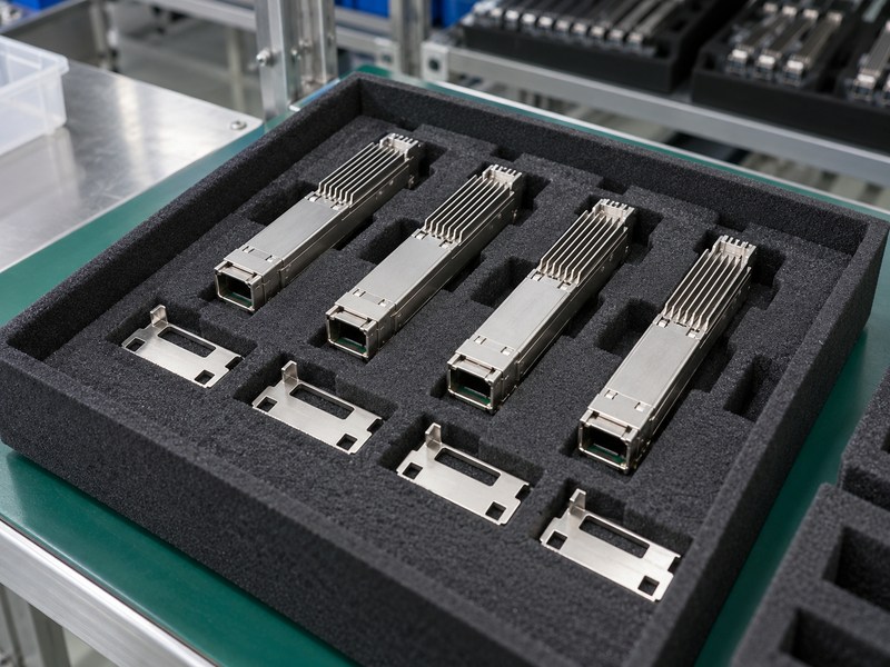
Approve a representative mating assembly with its inspection results, thermal conditions and durability evidence. Record the changes that require further review, including material, finish, clip, cage or module substitutions. Send the cage and module drawings, power conditions and airflow restrictions when you contact us. Keep any approved exceptions in the release record so purchasing and assembly teams do not rely on separate email interpretations of the same requirement.
- Tie samples to the drawing revision.
- Define inspection and packing requirements.
- Require notice before an approved interface changes.
| Quotation input | Define before ordering | Retained record |
|---|---|---|
| Mechanical interface | Module, cage and retention | Released drawings |
| Thermal requirement | Reference temperatures and conditions | Qualification report |
| Production scope | Finish, inspection and protection | Approved order specification |
Release production against those records and review substitutions before accepting another batch.
Frequently asked questions
Q1: Can I replace a riding sink with a module that has fins?
Only if the host supports that module variant. Verify the cage, stops, keepouts and platform requirements before treating a similar connector as proof of compatibility.
Q2: What’s the best interface material for a sliding module?
Use a material and contact mechanism qualified for the required mating life. A low-resistance stationary pad can still fail through abrasion during insertion.
Q3: How do I know if more clip force will improve cooling?
Check the permitted load and the cause of poor contact. More force cannot safely correct every tolerance, surface or alignment problem.
Q4: Can I use room temperature in the thermal calculation?
Only when it represents the relevant air condition. Air reaching the optical port may already have been heated by neighboring components.
Q5: When should I repeat qualification?
Repeat the affected checks when changes alter the approved interface or operating conditions. Examples include a new cage, surface treatment, retention clip, module variant or airflow arrangement.