
Choose a semiconductor heat sink around the package’s heat path, allowable temperature, interface and installed cooling conditions. If your RFQ says “sandblasted aluminum heat sink semiconductor industry,” add the package details, finish boundaries and cleanliness requirements. A matte surface cannot rescue a poor contact joint or a blocked airflow path.
1. Is a sandblasted aluminum heat sink right for semiconductors?
A sandblasted aluminum heat sink can suit semiconductor industry equipment when its geometry, interface and cooling capacity meet the package requirements. Check where heat leaves the device before choosing the part. A package with a metal lid, an exposed thermal pad and a bare die can require very different cooling arrangements. Treat the semiconductor manufacturer’s mounting and thermal guidance as inputs to the mechanical design.
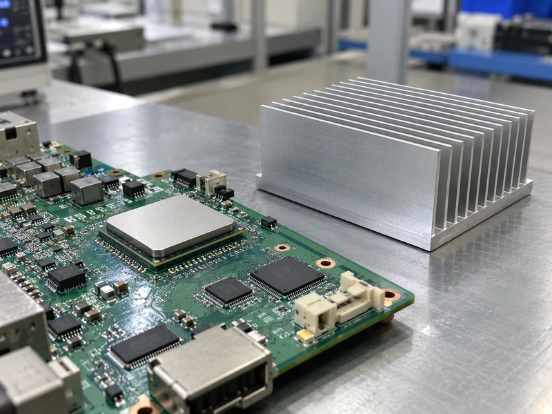
Which heat path are you trying to cool?
Identify the package surface intended for heat removal and the restrictions on contact pressure. A finned block resting on a plastic package top may not connect well to its dominant heat path. Conversely, a lid designed for a heat sink still needs a suitable interface and retention system. A bare die requires dedicated mechanical and thermal engineering; do not transfer a lidded-package mounting approach without reviewing stress and contact requirements.
- Confirm the package and its revision.
- Identify the intended cooling surface.
- Record mechanical limits before selecting retention.
| Package situation | Design input | Review before selection |
|---|---|---|
| Metal lid | Lid interface requirements | Contact and mounting load |
| Exposed board pad | Board heat path | Layout and thermal vias |
| Bare die | Die-specific assembly limits | Dedicated contact design |
Select the heat sink after you have identified the path it must serve.
2. Which aluminum heat sink manufacturing route should you use?
For semiconductor industry use, a sandblasted aluminum heat sink may start as an extrusion, a machined part or another qualified construction. Blasting is a finishing operation, so it does not identify how the fins and base were formed. Compare manufacturing routes against geometry, production quantity and thermal requirements. Also check whether later machining leaves enough base thickness beneath the device footprint and mounting features.
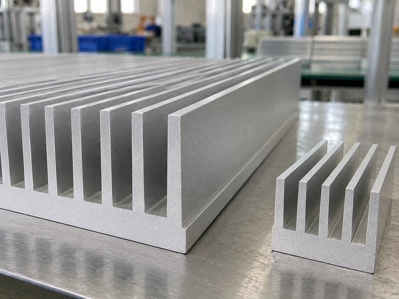
What makes an extrusion a reasonable candidate?
An extrusion offers a continuous profile that can be cut and machined for the assembly. Its feasibility still depends on alloy, die design, wall thickness and dimensional limits agreed with the manufacturer. Higher fin density alone does not prove better installed cooling because airflow resistance can also increase. If an extrusion cannot meet your envelope, compare other constructions using the same thermal conditions instead of assuming a process name guarantees a result.
- Review the actual profile with the supplier.
- Include machining and finishing in cost comparisons.
- Qualify the final assembled configuration.
| Route | Useful selection question | Evidence needed |
|---|---|---|
| Extruded profile | Can the section meet the envelope? | Profile and tolerance review |
| Machined part | Does geometry justify machining? | Drawing and cost review |
| Other fin construction | Is it suitable at the operating point? | Mechanical and thermal evidence |
Keep the manufacturing choice tied to the released drawing and tested assembly.
3. Where can a semiconductor heat sink be sandblasted?
In semiconductor industry assemblies, a sandblasted aluminum heat sink should have explicit finishing boundaries around package lands, threads and other functional surfaces. Specify the final contact condition rather than allowing the blast operator to infer it. The outer fins and the package land can need different surface treatments. Include any later anodizing or final machining in the same reviewed manufacturing sequence.
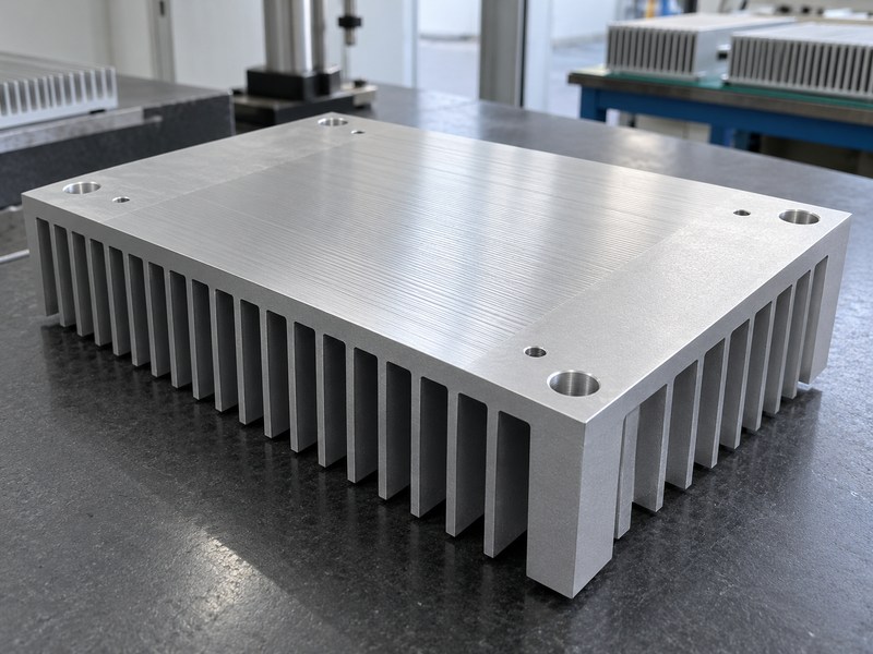
What must remain under dimensional control?
Review the contact land’s geometry and finish alongside hole positions, mounting standoffs and enclosure clearances. A small local step at a masking boundary can affect seating when it enters the package footprint. Check the final part after every operation that can alter those features. If a supplier proposes finish-machining the land after blasting, confirm the stock allowance, cleaning route and protection needed before delivery to electronics assembly.
- Mark the package footprint on the drawing.
- Define protected threads and locating features.
- Inspect the finished contact surface.
| Surface zone | Primary concern | Control |
|---|---|---|
| Package land | Contact quality | Drawing-based surface limits |
| External fins | Texture and geometry | Approved finish process |
| Retention feature | Load and alignment | Final dimensional inspection |
Approve the surface map before the supplier starts production finishing.
4. How clean should a semiconductor heat sink be?
A sandblasted aluminum heat sink for semiconductor industry equipment must meet the specific assembly’s particle and residue requirements. There is no single cleanliness class implied by the word semiconductor. A packaged-device control board differs from equipment operating near exposed wafers or sensitive optical surfaces. State where the part will be used and obtain the customer’s acceptance method before selecting blasting, cleaning and handling steps.
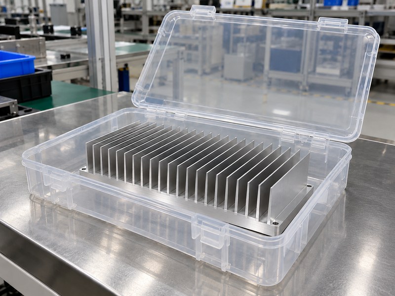
When should you challenge the finishing choice?
If the assembly cannot tolerate loose or embedded abrasive, review whether blasting belongs in the route at all. Cleaning cannot automatically demonstrate that every embedded particle has been removed. Ask how the process is validated at channel roots, blind features and masked boundaries. For particle-sensitive equipment, approval may require a different finish or a more demanding cleaning and verification route than a general industrial heat sink receives.
- Define the actual assembly exposure.
- Separate loose particles from embedded residue.
- Protect accepted parts during transport and storage.
| Application setting | Question to resolve | Acceptance basis |
|---|---|---|
| Enclosed control board | What debris can reach electronics? | Assembly specification |
| Optical equipment | Can particles reach sensitive surfaces? | Customer cleanliness plan |
| Wafer-adjacent equipment | Is this finish allowed? | Explicit process approval |
Do not label a part cleanroom-compatible without the relevant qualification evidence.
5. How should the semiconductor thermal interface be specified?
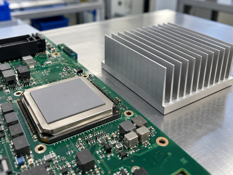
For semiconductor industry use, a sandblasted aluminum heat sink needs a defined thermal interface between the approved package surface and the heat sink land. Select the material for the gap, pressure, temperature and electrical requirements. Keep its installation procedure with the assembly drawing. A nominal material conductivity does not by itself describe the resistance of the installed joint or its behavior after service exposure.
What controls the installed interface?
Bond-line thickness, contact pressure, surface condition and coverage all affect the joint. Confirm whether the selected material requires compression, controlled dispensing or another installation method. Do not stack pads or add extra grease to compensate for an unexplained mechanical gap. Package mounting guidance identifies surface roughness, flatness and alignment as contributors to interface resistance; the assembly must control those factors together.
- Match the interface to the package limits.
- Control thickness and installed pressure.
- Review rework and long-term material behavior.
| Interface input | What to specify | Verification |
|---|---|---|
| Material | Approved product and condition | Incoming identity check |
| Thickness | Installed gap or bond line | Assembly method |
| Pressure | Allowed load range | Retention review |
Validate the complete joint rather than comparing materials by conductivity alone.
6. How should a semiconductor heat sink be retained?
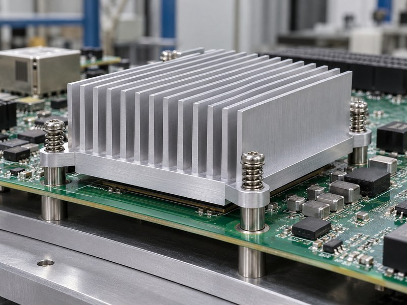
A sandblasted aluminum heat sink in semiconductor industry equipment needs retention that maintains contact without exceeding package or board limits. Consider the force path through springs, fasteners, standoffs and any backplate. The board should not become an uncontrolled spring under the heat sink. Review the assembly with the component supplier’s permitted load, mounting pattern and service conditions before choosing a screw size or torque.
Why is torque alone insufficient?
Fastener torque depends on thread condition, friction and the joint design, so it does not directly establish the pressure on the package. Springs or controlled stops may help define the intended load when used in a qualified assembly. Check clearance around components and the underside of the board. For repeated installation or rework, verify that the procedure preserves the interface and does not bend the board or damage package features.
- Define the load-bearing supports.
- Review component and tool clearance.
- Validate the installation sequence.
| Retention element | Design question | Evidence |
|---|---|---|
| Spring | What load occurs at installed height? | Load-deflection data |
| Standoff | Where does force close through the assembly? | Mechanical drawing |
| Backplate | Is the board supported appropriately? | Structural review |
Release a mounting procedure with the heat sink instead of leaving assembly pressure to operator judgment.
7. How does airflow affect semiconductor heat sink selection?
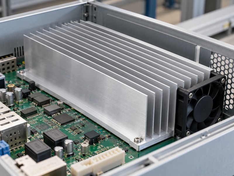
Airflow affects a sandblasted aluminum heat sink used in semiconductor industry equipment through the amount and temperature of air reaching its channels. Check the complete enclosure, including filters, ducts and neighboring heat sources. A fan’s free-air flow cannot establish flow through the installed heat sink. Test or model the operating arrangement before choosing a fin pattern from an open-air catalog rating.
What happens when the air budget is insufficient?
Review flow bypass, inlet heating and available fan pressure before increasing fin density. More fins can increase surface area while also increasing resistance to airflow. If the required temperature cannot be met within the acoustic, space or air-pressure limits, compare a different architecture. A hybrid liquid-cooled heat sink introduces separate coolant, sealing and reliability requirements that belong in a new system review.
- Measure or justify inlet air conditions.
- Check the fan operating point.
- Review the intended maintenance condition.
| Airflow issue | Possible consequence | Review action |
|---|---|---|
| Bypass | Air misses useful fin area | Duct and clearance review |
| Heated inlet | Less temperature margin | Enclosure thermal assessment |
| Restricted filter | Lower installed flow | Maintenance-condition test |
Select the cooling architecture against the limits of the complete system.
8. Does the semiconductor mounting need electrical isolation?
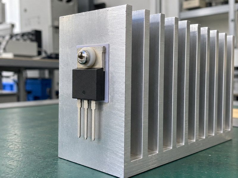
A sandblasted aluminum heat sink used in semiconductor industry power assemblies may need electrical isolation when a package’s exposed metal carries a potential different from the sink. Check the actual device and circuit. Neither a matte texture nor a black surface establishes the required insulation. Define the insulating material, fastener isolation, creepage, clearance and verification with the electrical design requirements for the product.
Which mechanical details can defeat isolation?
A conductive screw, damaged pad or uncovered package edge can create an unintended connection even when most of the interface appears insulated. Review the full fastener path and the material’s installed thickness. Electrical requirements and thermal resistance interact, so evaluate both before approving a substitution. Use the device and insulation suppliers’ instructions for the specific construction; do not transfer a torque value or isolation claim from an unrelated package.
- Identify exposed conductive package surfaces.
- Check screws, washers and edges.
- Verify the assembled insulation system.
| Potential path | Design control | Acceptance evidence |
|---|---|---|
| Package to sink | Qualified interface | Specified electrical test |
| Mounting screw | Approved isolation details | Assembly inspection |
| Exposed edge | Required spacing | Drawing and design review |
Approve the electrical and mechanical details together before thermal qualification.
9. How do you validate a semiconductor heat sink thermal budget?
Validate a sandblasted aluminum heat sink for semiconductor industry equipment with a thermal model appropriate to the device and a test of the intended assembly. A simple series resistance budget applies only when its assumed heat path reasonably represents the package. The thermal design guide explains the junction, case, interface and sink contributions for a suitable lid-cooled arrangement. Other packages can need different models.
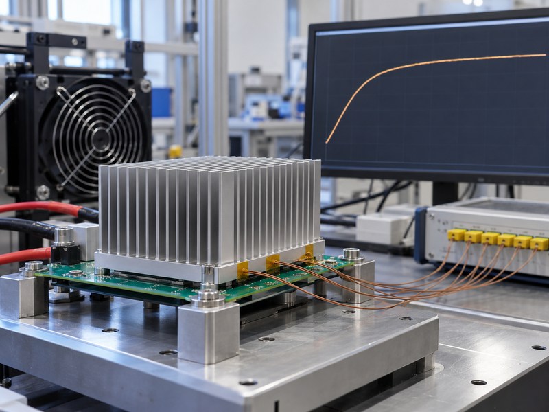
What does an initial calculation tell you?
As an illustrative design calculation, assume 100 W follows the modeled path, inlet air is 40°C and the junction design target is 100°C. If junction-to-case resistance is 0.15 K/W and interface resistance is 0.10 K/W, the remaining sink-to-air allowance is 0.35 K/W. These are hypothetical inputs, not product ratings. Check source assumptions, spreading, transients and test uncertainty before applying the estimate to a real device.
- Use device-specific thermal information.
- Account for the installed interface.
- Verify the result under operating conditions.
| Budget term | Illustrative input | Meaning |
|---|---|---|
| Total allowance | 0.60 K/W | Temperature rise divided by power |
| Package plus interface | 0.25 K/W | Assumed series contributions |
| Sink allowance | 0.35 K/W | Remaining modeled resistance |
The pictured trace shows a qualitative stabilization trend and provides no measured device temperatures.
10. What should a semiconductor heat sink approval include?
A sandblasted aluminum heat sink semiconductor industry RFQ should identify the package, drawing, interface, operating conditions and required acceptance evidence. Keep production approval tied to the tested configuration and final finishing route. Include the inspection, cleaning, packing and change-control requirements in the release. A new coating supplier or a substituted interface material can change the approved condition even when the external dimensions remain unchanged.
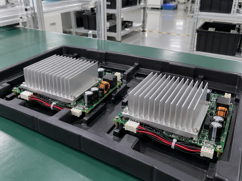
What should you send for engineering review?
Provide the device data, power profile, ambient conditions, available airflow and mounting restrictions. Add the cleanliness requirement and identify any customer restrictions on abrasive finishing. When you contact us, include the assembly envelope and the conditions behind your temperature target so the review can address the actual installation. Retain the approved sample, drawing revision and qualification report together before releasing production purchases.
- Identify material and finish substitutions requiring notice.
- Document the approved thermal interface.
- Preserve traceability from test sample to production.
| Approval item | Required definition | Review trigger |
|---|---|---|
| Device and mounting | Package-specific limits | Component change |
| Surface and cleaning | Approved final condition | Process substitution |
| Thermal qualification | Operating boundaries | Power or enclosure change |
Review changes against those boundaries before accepting another production configuration.
Frequently asked questions
Q1: Can I use the same heat sink on every package size?
Only after reviewing contact area, heat path, mounting load and thermal conditions. Similar power ratings do not establish mechanical or thermal equivalence.
Q2: What’s the best surface finish for a chip contact land?
Use the package and interface requirements. The contact land often needs separate dimensional and surface controls from the visible blasted exterior.
Q3: How do I know if the part suits a clean assembly?
Define the assembly’s particle and residue limits, then verify the final delivered condition. A visual inspection or a cleanroom label alone cannot establish compliance.
Q4: Can I use junction-to-ambient resistance as a sink rating?
No. Package junction-to-ambient data describes its defined test configuration. Select a model and heat sink rating suited to your actual heat path and installation.
Q5: When should I consider a liquid cold plate?
Consider it when air cooling cannot meet the temperature requirement within the system’s limits. Review coolant compatibility, flow, pressure, sealing and service requirements as part of that change.