
Choose an aluminum heat sink profile by matching its continuous section, mounting features and finished interfaces to the assembly. A catalog envelope cannot show whether a wall is suitable for a fastener or whether a fin channel remains open after installation. For aluminum profile heat sink structural components, start with the required heat and load paths, then review the extrusion and secondary operations needed to produce that geometry.
This guide focuses on selecting and specifying the profile as a manufactured component. It covers section geometry, extrusion feasibility, machining, finishing and sample acceptance. Keep the finished drawing and operating brief together so the supplier can evaluate the supplied part rather than a generic family of similar-looking sections.
1. What does a heat sink profile define?
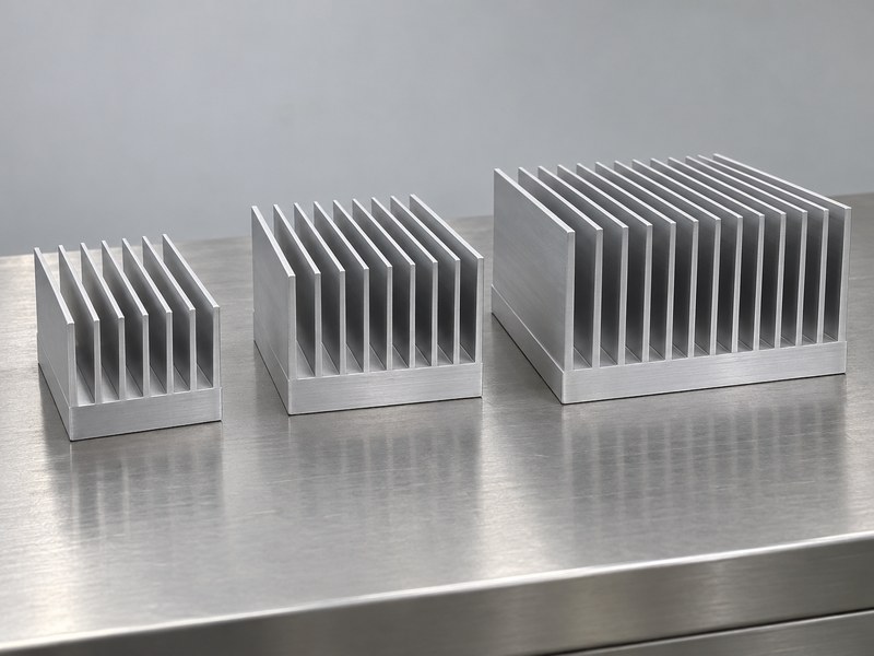
An aluminum heat sink profile defines a cross section that can continue along the extrusion length. That section can include a thermal base, fins, walls, grooves and supporting lands. Supplied length and secondary machining then turn the profile into a particular component. Identify which features belong to the original section and which are created afterward, because those choices affect manufacturing, inspection and the supplied scope.
How should you compare catalog sections?
Compare controlled section drawings rather than relying on photographs or overall width alone. Check base thickness, fin spacing, wall arrangement and the locations available for mounting. Establish the material and supplied condition associated with each option. If a catalog section is proposed as a substitute, review the functional differences before accepting it as equivalent to a part that was already evaluated.
- Obtain the section drawing and material condition.
- Separate extrusion features from later operations.
- Compare the functional surfaces and supporting lands.
| Profile information | Decision it supports |
|---|---|
| Section geometry | Heat path and available interfaces |
| Supplied length | Final component envelope |
| Secondary operations | Finished features and inspection scope |
Use the actual section drawing as the reference for the next design step.
2. Which functions should shape the cross section?
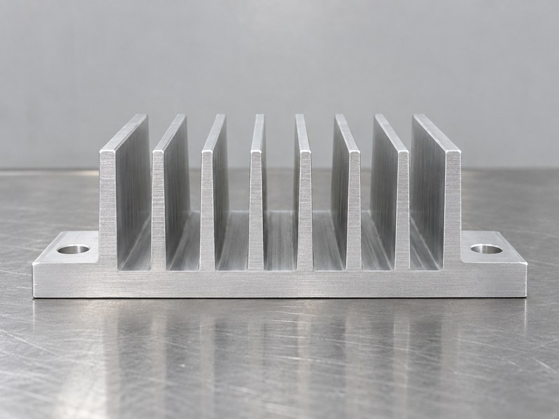
Shape an aluminum heat sink profile around the functions that must share its cross section. The base may spread heat, a wall may locate electronics and a mounting land may transfer loads into a chassis. Those functions can compete for space and material. Mark them on the design brief so a manufacturing adjustment does not remove metal from a supporting section or obstruct a needed cooling passage.
Which requirements should be treated as interfaces?
Identify device pads, locating features, fastener lands and any cover or seal contacts. Define the conditions that apply to those features, including final dimensions and permitted movement where relevant. Leave cosmetic areas distinguishable from functional ones. The supplier can propose a more practical section when the drawing makes clear which shapes are required and which can change without affecting the assembly.
- Map heat, supporting and locating functions.
- Mark interfaces that must be preserved.
- Identify geometry that is open to manufacturing adjustment.
| Section function | Requirement to define |
|---|---|
| Thermal spreading | Source location and usable base |
| Equipment support | Loads and supporting geometry |
| Component location | Datums and final mating features |
Review the cross section as a functional component rather than an outline alone.
3. How should fin dimensions be selected?
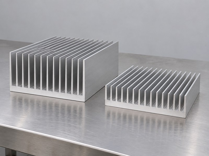
Select aluminum heat sink profile fins from the required heat transfer, installed airflow and manufacturing feasibility. Height, thickness and spacing affect several aspects of the design at once. Dense surfaces can increase nominal area while making flow or cleaning more difficult. Thin or tall features can also change handling and production concerns. Avoid choosing dimensions from an isolated claim that more fins always provide more cooling.
What should a supplier’s feasibility review include?
Ask the supplier to assess the proposed geometry with the intended alloy, section size and production route. Review any suggested change for its effect on thermal performance and installation clearance. Keep the air path visible, including brackets and covers around the profile. A manufacturable section still needs a cooling evaluation, and an attractive thermal model still needs a practical production plan.
- Define airflow and installation constraints.
- Review fin geometry with the extrusion supplier.
- Check the functional effect of proposed changes.
| Fin variable | Tradeoff to review |
|---|---|
| Height | Cooling surface, envelope and support concerns |
| Spacing | Air passage and contamination access |
| Thickness | Heat conduction and production feasibility |
Approve the final fin arrangement against both manufacturing and thermal requirements.
4. Which mounting features belong in the profile?
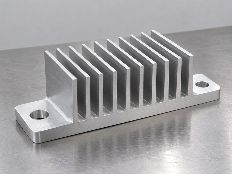
Include mounting features in an aluminum heat sink profile when their geometry supports the defined load path and assembly process. Integral lands, screw-port features or locating grooves may reduce later work, but they still need suitable dimensions and access. A feature’s presence in an extrusion does not establish its allowable load. Review its section, finished condition and interaction with the mating hardware.
What should you check before adding holes or slots?
Review the intended heat sink mounting hardware, tool access and datums. Establish which features will be machined after extrusion and whether finishing affects their final fit. Keep fastening forces off cooling fins unless the design explicitly evaluates that arrangement. If a slot permits movement, check how the complete joint retains the part and preserves the required contact condition.
- Identify supporting and locating features.
- Define later holes, slots and threads.
- Review hardware seating and assembly access.
| Mounting feature | Question for the drawing |
|---|---|
| Integral land | Which load or locating function does it serve? |
| Machined hole | From which datum is it accepted? |
| Slot or groove | What movement and retention are intended? |
Specify the finished joint rather than assuming the section feature completes the design.
5. What changes for a housing profile?
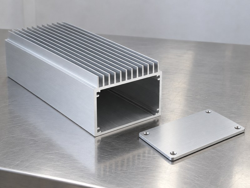
An aluminum heat sink profile used as a housing must provide the required space and interfaces inside as well as cooling surfaces outside. Locate the electronics and their heat-transfer paths before selecting the wall arrangement. A finned wall may need an internal thermal land or another defined contact arrangement. Review the cover, seals and service openings as parts of the assembled product.
Which enclosure claims need separate evidence?
A heat sink enclosure is more than its extruded section. The end covers, connectors, fasteners and seals can affect both mechanical and environmental behavior. Define the required acceptance conditions for the complete assembly. A section drawing or surface finish description alone cannot establish a verified ingress rating, a supported load or acceptable device temperatures inside a populated housing.
- Place internal devices and thermal contacts.
- Define cover, connector and seal interfaces.
- Validate the required assembled condition.
| Housing element | Review focus |
|---|---|
| Extruded wall | Space, supporting section and heat path |
| End cover | Fit, fastening and sealing arrangement |
| Internal thermal land | Device contact and assembly access |
Select the profile with the populated enclosure arrangement available for review.
6. How do you assess extrusion feasibility?
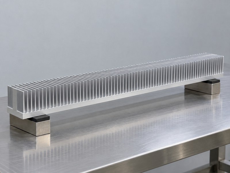
Assess an aluminum heat sink profile with an extrusion professional before treating a detailed cross section as ready for production. Feasibility depends on the section, material, tooling and process capability together. Local changes can affect metal flow, tooling and the finished geometry. Agree which features are fixed by function and which may be adjusted to make the part more practical to produce.
Which design discussions should happen early?
The industry extrusion design resources cover alloy selection, dies, tolerances and fabrication considerations. Use that framework to prepare questions for the supplier, rather than applying one generic dimensional limit to every profile. Ask the supplier to identify proposed allowances and assumptions. Review their functional effect before revising the drawing, and preserve the agreed section revision through prototype and production planning.
- Review material and section geometry together.
- Identify the supplier’s proposed allowances.
- Approve changes against functional requirements.
| Feasibility input | Supplier response to request |
|---|---|
| Functional section | Features that need adjustment or confirmation |
| Material condition | Proposed alloy and supplied state |
| Tooling plan | Assumptions affecting the finished component |
Resolve the open geometry questions before committing to a production route.
7. Which secondary operations need their own definition?
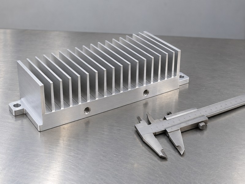
An aluminum heat sink profile often needs cutting, drilling, tapping or contact-face machining after extrusion. Define those operations through finished features and datums. The supplier needs to know which surfaces locate the part during machining and which final dimensions govern assembly. A raw profile specification cannot automatically cover the component’s finished cut length, hole pattern and contact geometry.
What should the machining quotation include?
For CNC machined heat sinks, identify the required features, inspection condition and any permitted process sequence. State whether dimensions apply before or after finishing. Include burr removal and the condition of cut ends where they affect handling, fit or protection. Compare quotations using the same finished scope so a low price is not simply omitting a required operation.
- Define length and machined features separately.
- Use functional datums for acceptance.
- State the final condition of edges and contact faces.
| Operation | Finished requirement |
|---|---|
| Cutting | Length and end condition |
| Drilling or tapping | Location, engagement and usable feature |
| Contact machining | Final face geometry and surface condition |
Keep the extrusion and machining drawings aligned with the same part revision.
8. How should finish and dimensional allowances be specified?
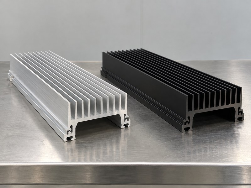
Specify an aluminum heat sink profile finish with the functional surfaces and final dimensions visible. Coverage can affect contact, bonding or mating fits, so color alone is incomplete. Identify masked lands and any permitted machining after finishing. Ask the supplier how the selected process affects the finished features instead of applying one universal growth allowance to every treatment.
Which surfaces need separate acceptance conditions?
Keep device pads, mounting lands, threads and seal surfaces distinct from appearance-only areas. If the profile is cut from finished stock, define the condition required at the exposed ends. Review any repair or reprocessing proposal for the dimensions and material condition it can affect. The accepted sample should represent the same sequence and final requirements planned for delivered production parts.
- Specify process and coverage, not color alone.
- Identify final fits and masked areas.
- Define the condition of exposed or remachined surfaces.
| Finished area | Acceptance detail |
|---|---|
| Device land | Contact geometry and treatment |
| Mating feature | Final fit after processing |
| Cut end | Edge and surface condition at delivery |
Review finish decisions as part of the functional component specification.
9. How should a profile prototype be evaluated?
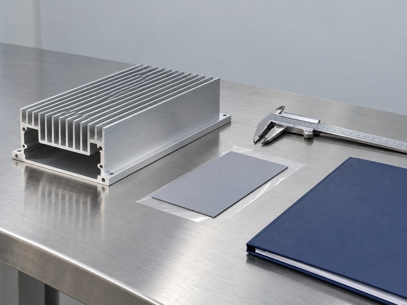
Evaluate an aluminum heat sink profile prototype using the finished drawing and the assembly’s operating requirements. Check the section, machined interfaces and material condition before interpreting a performance result. Identify whether the sample represents the proposed production route. A machined demonstration part may answer a fit question while leaving extrusion or finishing questions open for a later sample.
What should the sample review record distinguish?
State which questions the prototype answered and which remain unresolved. Keep dimensional, mechanical and thermal acceptance separate where they require different evidence. Record interface materials, mounting and cooling conditions during a functional test. If the supplier proposes a production change afterward, review the affected checks rather than assuming the first sample approval covers every later construction.
- Identify the prototype’s production relevance.
- Check finished fit and functional interfaces.
- Retain the scope and limits of the approval.
| Prototype question | Evidence to retain |
|---|---|
| Does it fit? | Finished dimensions and assembly review |
| Does it perform? | Required mechanical and thermal conditions |
| Can it be produced? | Process plan and representative sample evidence |
Use the sample review to close specific requirements before production release.
10. What should the profile RFQ and delivery plan contain?
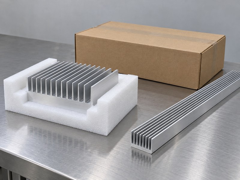
An aluminum heat sink profile RFQ should define the section, supplied length, secondary operations, finishing and acceptance records together. Identify quantity and delivery condition so suppliers evaluate the same scope. Include protection for thin fins and functional faces during packaging. A section that meets its drawing at the factory still needs a delivery arrangement that preserves its accepted condition.
How do you control future profile changes?
Retain the accepted extrusion, machining and finish revisions with the order. Define how proposed tooling, material or process changes will be reviewed. For repeat purchases, check whether the next supply uses the same configuration and which evidence accompanies it. A familiar profile identifier or similar envelope cannot establish that supporting lands, contact geometry and cooling passages remain unchanged.
- Supply the complete finished-part definition.
- Agree on inspection and packaging requirements.
- Define approval for relevant production changes.
| Order item | Information to preserve |
|---|---|
| Drawing set | Section and finished interfaces |
| Acceptance plan | Measurements and functional evidence |
| Change process | Control of later tooling or source revisions |
Send your profile drawing and assembly requirements when you contact us for a feasibility and manufacturing review.
Frequently asked questions
Q1: Can I use a stock profile for a structural cooling part?
Yes, if the section and finished features meet the application’s requirements. A stock designation does not replace the mechanical and thermal review.
Q2: What’s the best way to choose fin spacing?
Evaluate the installed airflow, heat input and manufacturing constraints together. Avoid selecting spacing from surface area alone.
Q3: How do I know which tolerances apply after finishing?
State the final inspection condition on the drawing and agree it with the supplier. Separate raw-profile and finished-component requirements.
Q4: Can a machined prototype qualify an extruded production part?
Only for the questions it represents. Confirm the remaining process, material and geometry requirements with suitable production-representative evidence.
Q5: Should the RFQ include protective packaging?
Yes. Define how the base, fins and contact faces must be supported and protected at delivery.