
Check an aluminum heat sink for strength by defining its loads, tracing the supporting features and assessing deformation as well as failure. A heavy base or a material label does not establish an allowable load. For a structural integrity aluminum heat sink review, identify the actual part condition, joint arrangement and acceptance limits before comparing candidate designs. The review must cover the configuration that will be installed.
This guide focuses on mechanical integrity and the cooling functions that mechanical changes can affect. It covers bases, mounting features, fins, joints and prototype evidence. It does not assign a universal load rating to a cooler category. Your drawing and validation plan need the application-specific conditions that make a strength or stiffness result meaningful.
1. What should a mechanical integrity review establish?
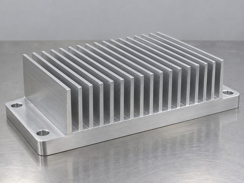
An aluminum heat sink integrity review should establish whether the supplied component can perform its defined mechanical role while retaining required contact and cooling functions. That role may include supporting its own mass, carrying a device or forming part of an enclosure. Name the role explicitly. Otherwise, a thermal supplier and a mechanical designer may evaluate different responsibilities while discussing the same part.
Which acceptance conditions should be separated?
Separate material failure, excessive displacement, loss of contact and joint loosening where they are relevant. A component can remain unbroken while its movement makes the assembly unacceptable. Define the limiting interfaces and the condition in which they must be checked. Include any required state after testing, such as retained fastening, usable threads or an acceptable device contact face.
- Identify the mechanical function of the supplied part.
- Define the relevant failure and displacement criteria.
- Include contact and joint condition in acceptance.
| Review question | Requirement to define |
|---|---|
| Does it carry the load? | Load cases and material condition |
| Does it move too far? | Displacement and interface limits |
| Does it retain function? | Contact, fastening and post-test condition |
Use defined criteria rather than an informal judgment that the part feels solid.
2. How do you trace the load path?
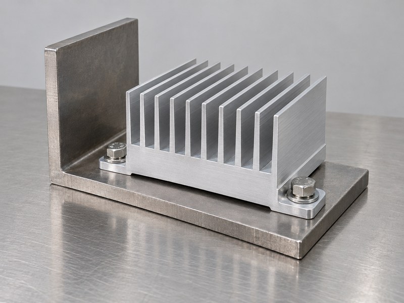
Trace an aluminum heat sink load from its point of application through the base, ears or walls and into the supporting assembly. Identify the constraints and any offset between the load and its supports. An eccentric load can introduce bending or twisting in addition to a direct force. Include the bracket or chassis when its stiffness affects how the cooler is supported.
Which operating and handling cases belong in the review?
Record the conditions that the installation requires, including relevant orientation, vibration, shock, assembly and service loads. Do not assume that all fasteners share a load equally. Their location, the joint stiffness and the surrounding geometry can affect the distribution. The supplier needs the intended boundary conditions to assess the same load path that the final assembly will impose.
- Mark force locations and directions.
- Identify supports and permitted movement.
- Include relevant offsets and load combinations.
| Load-path detail | Question to resolve |
|---|---|
| Applied load | Where and in which direction does it act? |
| Supporting feature | Which metal section carries it? |
| Assembly constraint | How does the bracket or chassis restrain movement? |
Keep those boundary conditions with any calculation or test result.
3. Which material information is actually required?
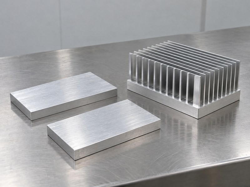
An aluminum heat sink mechanical assessment needs material information that represents the supplied alloy, temper and manufacturing condition. A generic conductivity value does not describe strength or fatigue behavior. Identify the properties needed for the review and the temperatures at which they apply. If joining or processing changes the relevant material condition, the assessment needs data appropriate to those affected areas as well.
What should the purchasing specification preserve?
State the required identity and records on the drawing or purchase specification. Public extrusion design guidance includes alloy selection and fabrication considerations, but a general guide does not identify the material in a delivered batch. Agree what traceability is required and how substitutions will be reviewed. A different alloy or temper should not be accepted solely because its appearance matches the approved sample.
- Specify material condition where it affects acceptance.
- Use property data for the relevant process and temperature.
- Define identification and substitution controls.
| Material item | Evidence to establish |
|---|---|
| Alloy and temper | Required supplied condition |
| Property data | Applicability to the assessment |
| Batch identity | Agreed connection to delivered material |
Keep material identity distinct from the finish or color applied afterward.
4. Why is stiffness different from strength?
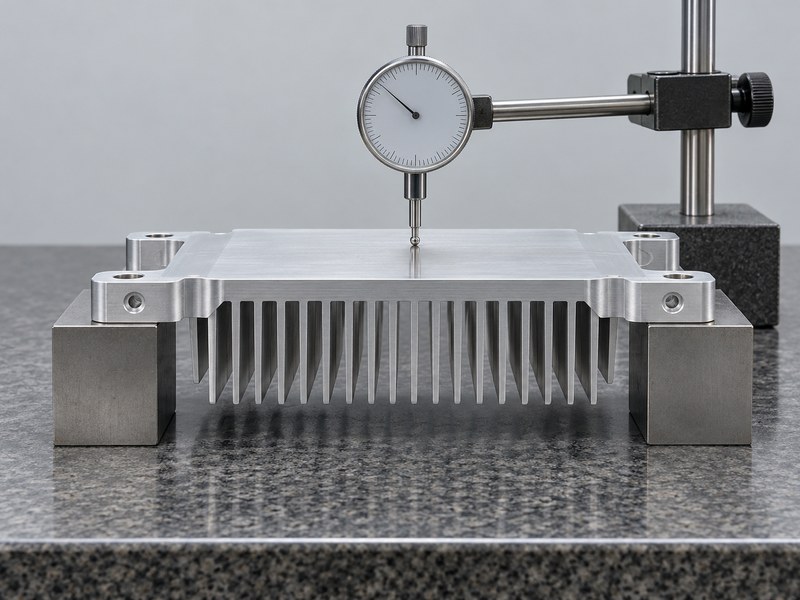
An aluminum heat sink can satisfy a material strength criterion while deforming enough to disturb its thermal interface, fit or seal. Stiffness concerns the movement produced by loads and constraints, while strength concerns the relevant failure criteria. Review both where the design depends on controlled contact. The base section, support spacing and load location all belong in that evaluation.
How should contact-face deformation be checked?
Define whether the requirement applies to the loose part, the restrained assembly or both. Use a measurement and support arrangement consistent with that definition. A fixture can bend a thin section or conceal a free-state shape difference. For thermal contact, also review the assembled pressure and gap distribution rather than assuming a good loose-part flatness value guarantees the intended device interface.
- Define the state in which geometry is assessed.
- Review the base under assembly loads.
- Connect movement limits to functional interfaces.
| Mechanical result | Functional question |
|---|---|
| Base displacement | Does the device contact remain acceptable? |
| Wall movement | Does the housing retain required fit or sealing? |
| Mount movement | Does the supported assembly remain correctly located? |
Assess the consequence of movement, not just whether the metal remains intact.
5. What should you check at threads and bosses?
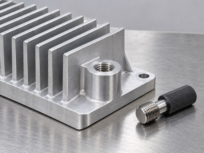
Check an aluminum heat sink threaded joint as a combination of fastener, engagement, supporting section and assembly method. A hole’s nominal thread size does not establish the load capability of the surrounding metal. Review the boss or ear geometry and the direction of the joint load. Include local contact and seating features where they affect the behavior of the assembled connection.
Which fastening details need control?
Review the specified heat sink mounting hardware together with engagement, seating and retention requirements. Tightening torque alone does not uniquely establish clamp force, because joint and fastener conditions also matter. Define the assembly process appropriate to the design, and verify the finished threaded features after operations that can affect them. Keep repair or rework decisions separate from a routine inspection result.
- Identify the supporting section around the thread.
- Define engagement and fastening conditions.
- Check finished features using the agreed method.
| Joint detail | Review focus |
|---|---|
| Boss or ear | Local section and load transfer |
| Thread engagement | Required fastener interaction |
| Seating surface | Load distribution and assembly consistency |
Evaluate the complete joint instead of assigning a rating from thread size alone.
6. Can cooling fins serve as structural attachments?
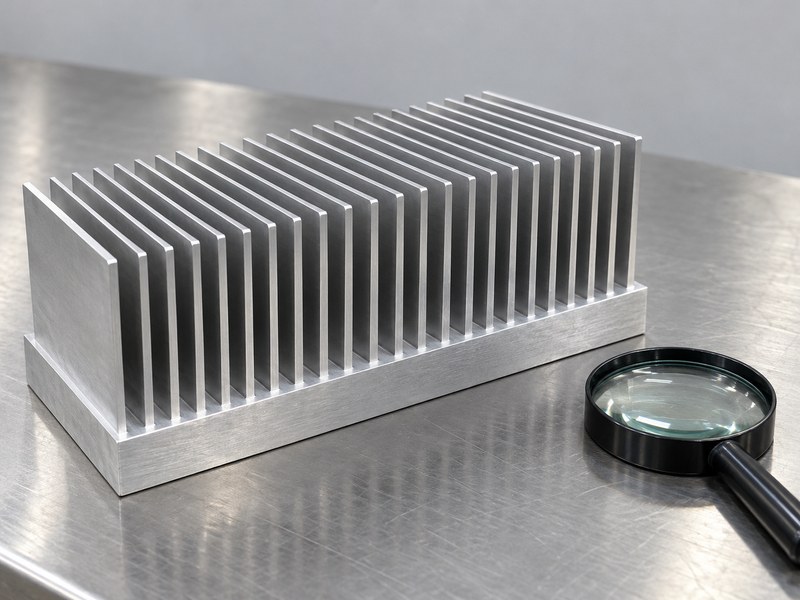
Cooling fins on an aluminum heat sink should serve as attachments only when the design and validation explicitly support that role. Thin extended surfaces may be selected primarily for heat transfer and manufacturing feasibility. Loading a fin can introduce bending, damage a joint or alter channel geometry. Use the intended supporting features wherever the assembly permits, and assess any exceptional fin loading as part of the mechanical requirement.
What handling conditions should be considered?
Assembly fixtures, packaging and service tools can load fins even when operating loads do not. Identify where the part may be gripped, clamped or stacked. Specify support at suitable solid features and keep accidental fin loading out of the normal process. If a fin is damaged, assess the consequence for both geometry and cooling rather than assuming it is merely a cosmetic issue.
- Identify which surfaces may carry handling loads.
- Keep normal support on evaluated solid features.
- Review fin damage against functional requirements.
| Fin-related condition | Question to address |
|---|---|
| Device or bracket attachment | Was the fin evaluated for the load? |
| Assembly clamping | Can the fixture distort the cooling geometry? |
| Shipping support | Are thin features carrying stacking loads? |
Make the permitted support and handling locations visible to production teams.
7. How does temperature affect the mounting joint?
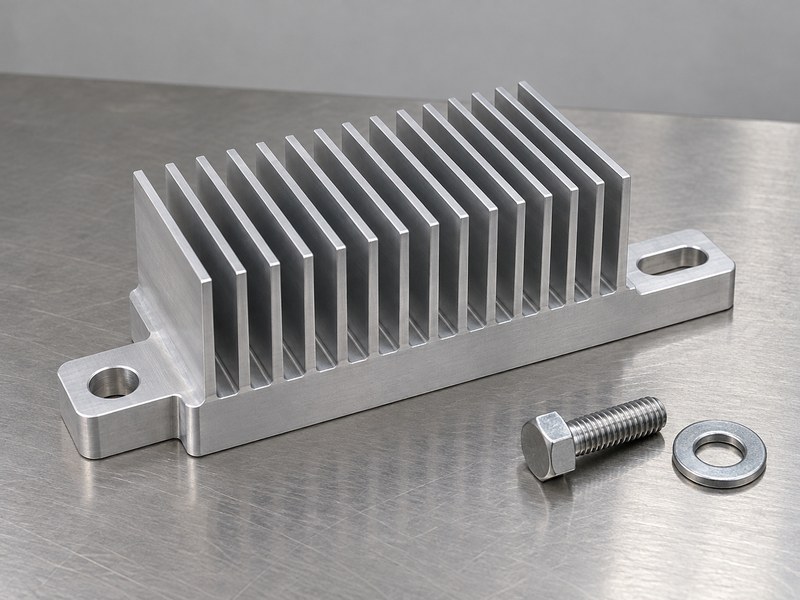
Temperature changes can affect an aluminum heat sink joint through expansion, constraints and the behavior of interface materials. Parts made from different materials may move differently over the operating range. Review the resulting contact force and displacement where they affect the assembly. A room-temperature fastening check does not establish that the same contact condition will be maintained when the equipment is hot or cold.
Which interface changes should be evaluated?
Consider whether the joint needs compliance or a controlled movement path, and assess the effects on locating and retention. If thermal pads form part of the interface, their compression and material behavior also belong in the review. A slot or spring element should address a defined requirement rather than being added without checking the rest of the joint. Validate the resulting assembly through its relevant temperature conditions.
- Review expansion with the actual constraints.
- Check retained contact and fastening behavior.
- Include interface materials in the joint model.
| Temperature-related effect | Functional consequence |
|---|---|
| Differential movement | Changes location or loads a constrained feature |
| Changed clamp condition | Alters contact or retention |
| Interface compression change | Affects the thermal and mechanical arrangement |
Use the required temperature range when evaluating the joint configuration.
8. Which manufacturing details need mechanical review?
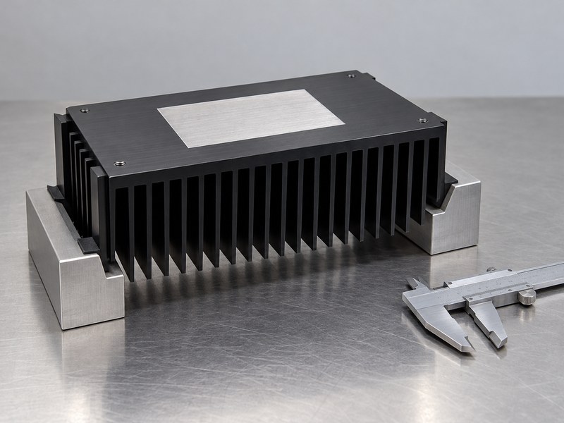
Manufacturing details can affect an aluminum heat sink through geometry, material condition and the final contact surfaces. Holes, slots, transitions and joined areas may change the load path or local response. Review those features in the finished design, including any operations after forming. A change that appears minor on a cooling drawing can affect the mechanical section or the condition of a critical interface.
What should production inspection verify?
Define the functional datums, final dimensions and material or process records required for acceptance. State which surfaces are inspected after machining and finishing. If a supplier proposes a different construction or repair, review the affected requirements before approving it. Inspection should verify the agreed finished configuration rather than attempt to recreate an unspecified engineering decision at the receiving bench.
- Review local features along the load path.
- Control the final geometry and process condition.
- Define approval requirements for construction changes.
| Production feature | Acceptance focus |
|---|---|
| Holes and slots | Finished location and supporting section |
| Contact lands | Final geometry and surface condition |
| Joined or processed areas | Applicable material and integrity requirements |
Tie production acceptance to the same configuration evaluated during design.
9. How should analysis and prototype testing work together?
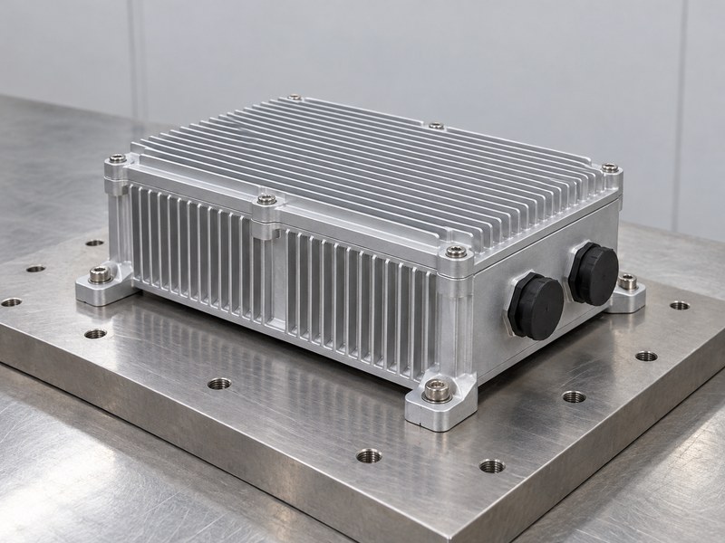
Use analysis and testing of an aluminum heat sink to answer the defined mechanical questions under stated conditions. A model depends on its material data, geometry, loads and constraints. A test depends on its fixture, sample condition and measurements. Neither result can be interpreted without those inputs. Identify which assumptions or interfaces need confirmation before treating a prototype as representative of production hardware.
Which post-test checks matter?
For a heat sink enclosure, assess the required locating, contact and sealing functions after the relevant exposure sequence. Check fastening and any surfaces whose movement could affect cooling. Repeat a thermal measurement where the mechanical test can change the heat path. Keep predicted values and observed results distinguishable, and investigate a disagreement instead of selecting whichever result appears more favorable.
- Document model and fixture boundary conditions.
- Identify assumptions that need prototype evidence.
- Recheck functions affected by the test sequence.
| Evidence type | Information to retain |
|---|---|
| Analysis | Inputs, assumptions and assessed criteria |
| Prototype test | Sample, fixture and applied conditions |
| Post-test inspection | Retained mechanical and thermal functions |
Use the combined evidence to resolve the design questions that remain open.
10. What belongs in a mechanical release record?
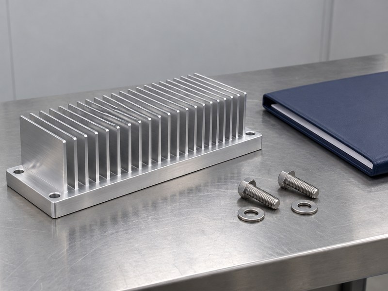
An aluminum heat sink release record should connect the accepted drawing, material condition, mounting arrangement and validation evidence. Identify the mechanical function and any operating limits that the assessment depends on. Retain the production inspection requirements and approved deviations. A later supplier or process change needs that reference so the team can identify which requirements may be affected.
How do you control a proposed substitution?
Compare the replacement against the relevant geometry, material, joint and contact requirements. Establish the additional analysis, sample review or test needed before accepting it. Keep the change decision linked to the part revision and production source. A similar external envelope or lower mass does not establish that the replacement follows the same load path or retains the evaluated cooling interface.
- Preserve the evaluated part and mounting configuration.
- Identify inspection and change-control requirements.
- Close unresolved mechanical assumptions before release.
| Release item | What it preserves |
|---|---|
| Functional drawing | Evaluated geometry and interfaces |
| Validation evidence | Meaning of the accepted result |
| Change requirements | Review of later construction or source changes |
Share the drawing, loads and acceptance requirements when you contact us about a prototype or finished cooling component.
Frequently asked questions
Q1: Can I judge strength from base thickness?
No. Loads, supports, material condition and local geometry also affect the result. Assess the finished configuration.
Q2: What’s the difference between a strong base and a stiff base?
Strength concerns the relevant failure criteria, while stiffness concerns movement under load. An assembly may need limits for both.
Q3: How do I know whether fins can carry a bracket?
Check whether that attachment was explicitly designed and validated. A cooling fin is not automatically an approved mounting feature.
Q4: Should I recheck cooling after mechanical testing?
Yes, when the exposure can change the joint or another part of the heat path. Compare results under appropriate controlled conditions.
Q5: Can I replace an alloy with one that looks the same?
Only through the agreed material and change review. Appearance does not establish equivalent mechanical or thermal properties.