
A typical air-cooled heat sink structure consists of a contact base, heat-spreading material, extended cooling surfaces and mounting interfaces. Choose those features as a connected heat path. A large fin array cannot compensate for poor device contact or air that bypasses the channels. Start with the heat source and follow the route that its energy must take into the surrounding environment.
This guide explains heat sink structure for engineers and purchasing teams comparing cooling components. It separates what each feature does from the evidence needed to select it. Use the actual heat loss, installation space and local cooling conditions for the design; overall dimensions or a catalog picture do not establish the installed temperature.
1. Which parts make up a heat sink structure?
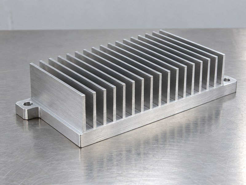
A heat sink structure usually brings a device contact surface, a spreading base and cooling surfaces into one assembly. The contact area receives heat from the source. The base distributes it toward the fins or pins, and those surfaces exchange heat with the surrounding medium. Mounting features keep the intended interface in place, while the installation determines how air can reach and leave the cooling surfaces.
How should you read a component drawing?
Identify which surface touches the heat source, where the mounting loads enter and which passages carry air. Check whether the base and fins form one continuous piece or use a separate joint. If the drawing includes a heat pipe, cold plate or another heat-transfer element, identify its role rather than assuming the visible fins describe the entire solution. The useful drawing shows the complete path that the performance claim covers.
- Locate the source-side contact surface.
- Trace the spreading and heat-rejection path.
- Identify mounts and any separate thermal joints.
| Feature | Primary function |
|---|---|
| Contact surface | Receives heat through the device interface |
| Base or spreader | Distributes heat toward cooling surfaces |
| Fins or pins | Provides surface area for heat exchange |
Use these functions to compare two designs that look different externally.
2. What does the base do in a heat sink structure?
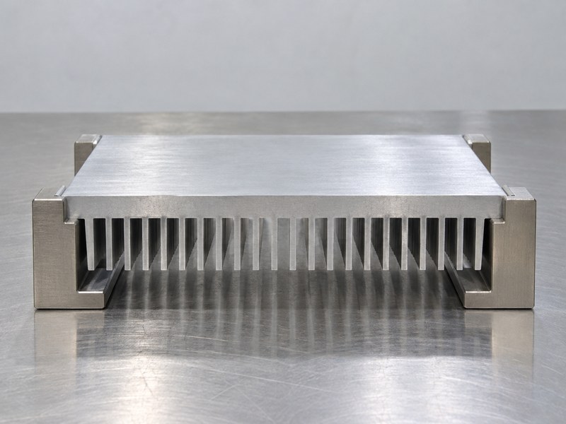
The base of a heat sink structure receives localized heat and spreads it toward a larger cooling area. Its thickness, source footprint and material affect that spreading path. The base also supports contact and mounting loads, so geometry must suit both the thermal and assembly requirements. A thicker base can change several properties at once, including mass, stiffness and conduction distance.
When should the contact footprint drive the review?
A small hot device on a broad base creates a different spreading problem from a distributed heat source. Review the device location and usable contact area before selecting a profile. For CNC machined heat sinks, identify which faces require final machining and how the supplier will verify them. Compare alternative bases under the same source and cooling conditions rather than judging thickness in isolation.
- Define the heat-source footprint and location.
- Review the complete spreading path.
- Control finished contact geometry and condition.
| Base input | Why it matters |
|---|---|
| Source size | Sets how localized the heat input is |
| Device location | Changes the path toward usable cooling area |
| Finished face | Affects the installed contact arrangement |
Choose the base with the source arrangement visible in the design brief.
3. How do fins and pins differ?
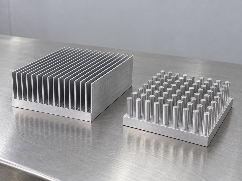
Fins and pins give a heat sink structure extended surfaces that can exchange heat with air. Straight plates create directional channels, while pin arrays can provide passages in several directions. Their performance depends on dimensions, spacing, airflow and the surrounding installation. The names plate-fin and pin-fin do not establish a universal ranking or a capacity that applies to every cooler in that category.
Why does additional area sometimes disappoint?
Area helps only when heat reaches it and the surrounding medium can remove that heat. Tall or dense features can create temperature gradients and flow restrictions. Narrow passages may also collect contamination in service. Review useful area and installed airflow together, and ask for data that identifies the source footprint and operating condition. A fin count by itself cannot show whether the proposed geometry addresses your thermal limit.
- Compare spacing and passage direction.
- Include height, thickness and available airflow.
- Review contamination and cleaning access where relevant.
| Surface arrangement | Question to evaluate |
|---|---|
| Straight fins | Can air follow the channels through the installation? |
| Pin array | How does the actual air approach the pins? |
| Dense features | Is heat transfer limited by spreading or flow? |
Select the geometry for the installation rather than for surface area alone.
4. Where does the interface layer belong?
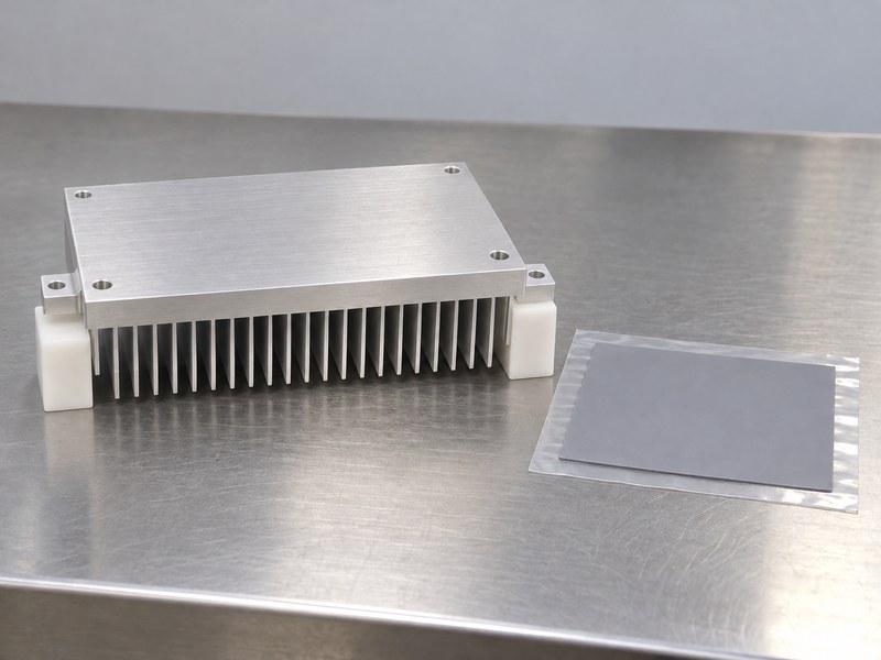
The interface layer sits between the heat source and the receiving surface of a heat sink structure. It addresses gaps and surface irregularities within a defined assembly. Its installed thickness and contact pressure can affect resistance, so the material cannot be selected from bulk conductivity alone. The device and cooler also need a mounting arrangement that maintains the required contact without damaging the assembly.
Which details should be specified together?
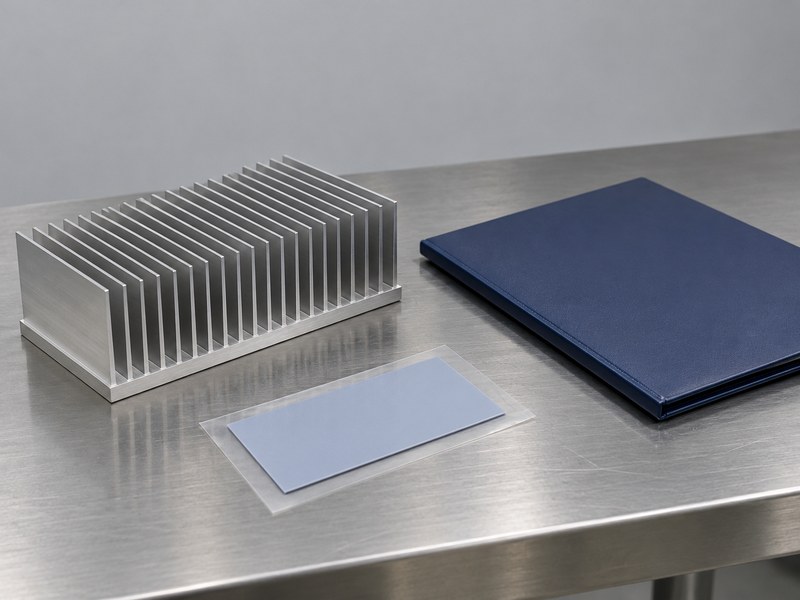
Define the gap range, material, placement and clamping method. If you use thermal pads, check their compressed condition and the device’s allowable force. A thicker pad is a different thermal and mechanical choice, even when it makes assembly easier. Keep the interface identity in the prototype record so later comparisons do not confuse a material change with a change in the metal cooler.
- Define the assembly’s actual gap range.
- Match pressure and material behavior.
- Record the installed interface condition.
| Interface detail | Design consequence |
|---|---|
| Thickness | Changes the through-layer heat path |
| Pressure | Affects contact and compression |
| Material identity | Determines the intended installed behavior |
Evaluate the interface as part of the cooling assembly.
5. What changes when the fins are joined separately?
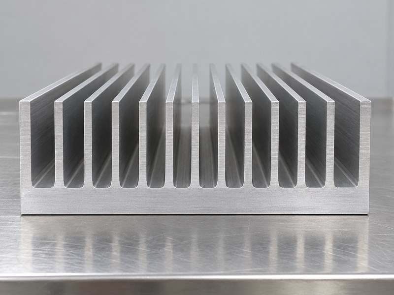
A heat sink structure with separately attached fins includes a joint that must transfer heat and retain the geometry. A one-piece extrusion avoids a separate fin-to-base assembly joint, while other manufacturing routes may provide different geometric options. Neither construction settles the design by itself. Review the joint, source arrangement and required environment for the actual component being offered.
What should you ask about a joined assembly?
Ask how the fins are attached, which inspections address the joint and what performance data represent the delivered construction. Mechanical handling and environmental exposure can matter where a joint is part of the heat path. Keep the accepted joining process under revision control. If a supplier changes the construction while retaining a similar external envelope, evaluate the affected thermal and mechanical requirements before accepting equivalence.
- Identify every separate joint in the heat path.
- Request construction-specific inspection information.
- Control relevant process and source changes.
| Construction detail | Evidence to request |
|---|---|
| One-piece section | Geometry and material condition |
| Attached fins | Joining route and joint acceptance |
| Changed construction | Review against the accepted requirements |
Compare finished constructions using the same source and cooling conditions.
6. How should air move through the structure?
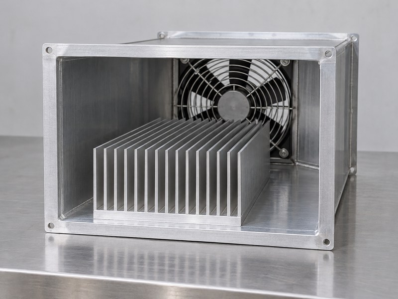
Air must reach the cooling surfaces and leave the heat sink structure through a usable path. For straight fins, the installed flow should suit the channel direction. Nearby walls, brackets and openings can change that flow or allow it to bypass the cooler. Review the complete enclosure and duct rather than applying a fan’s unrestricted airflow figure directly to a fin array.
Which assumptions differ for passive cooling?
Natural convection depends on orientation, surrounding clearance and local temperature conditions. Forced-air systems also depend on the fan’s operating point with the installed restrictions. Record those conditions with any resistance or temperature claim. If a packaging change moves a wall or blocks an outlet, reassess the relevant result instead of assuming the original cooler rating remains applicable.
- Define inlet and outlet locations.
- Check channel direction and bypass gaps.
- Include orientation and surrounding restrictions.
| Air-side detail | Review focus |
|---|---|
| Channel alignment | Useful flow through the array |
| Duct or enclosure | Restrictions and leakage paths |
| Local inlet | Temperature available for cooling |
Keep the air path visible in both the mechanical and thermal drawings.
7. How does manufacturing shape the available geometry?
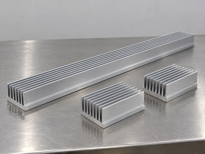
Manufacturing determines which heat sink structure can be produced consistently at the required quantity and condition. Extrusion creates a continuous section, while machining, forming, forging or assembled-fin routes offer different feature and volume tradeoffs. Identify the required geometry before treating those routes as interchangeable. The selected process must also support the contact faces, mounting features and inspection requirements on the finished drawing.
Which secondary operations should be identified?
List cut length, holes, slots, contact machining and any finishing that follows the main forming operation. Check which dimensions are inspected before and after those operations. A raw profile and a ready-to-assemble part are different supplied conditions. Ask the supplier to identify process allowances and drawing details that need clarification before a prototype or production quotation is accepted.
- Match the process to the functional section.
- List all remaining machining and finishing.
- Define the finished inspection condition.
| Manufacturing input | Question to resolve |
|---|---|
| Main process | Can it produce the required section? |
| Secondary features | Which operations and datums are needed? |
| Finished part | Which condition is accepted at delivery? |
Compare quotations using the same finished component definition.
8. How do you connect structure to a thermal budget?
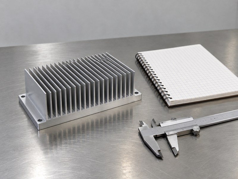
Connect a heat sink structure to its thermal budget by defining the allowed temperature rise and the heat that must follow the evaluated path. A simple steady-state resistance equals temperature rise divided by heat flow between stated locations. It is a useful selection input, but its meaning depends on those boundaries. A base-to-air resistance cannot automatically replace a complete device-to-air result.
What does a preliminary example establish?
Assume a base must stay at or below 85°C with 45°C local inlet air while receiving 40 W. The corresponding base-to-air allowance is 1 K/W before you reserve additional margin. These are illustrative inputs, not a rating for a particular cooler. Device and interface resistances remain outside that base-to-air calculation, and package thermal measurement guidance helps explain why measurement locations and parameters need careful interpretation.
- Use heat loss rather than total equipment power.
- Name the temperature and heat-flow boundaries.
- Reserve the margin required by the application.
| Illustrative input | Value |
|---|---|
| Allowed base rise | 40 K |
| Heat received by base | 40 W |
| Base-to-air allowance before margin | 1 K/W |
Use the budget to compare candidate structures under matching conditions.
9. When does the heat-transfer architecture change?
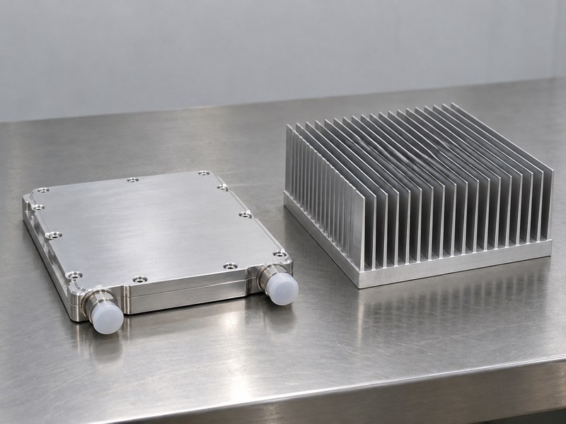
A heat sink structure may need a different architecture when direct conduction and the available air-side arrangement cannot meet the requirements. A spreader, two-phase component or liquid cold plate changes the path and introduces different interfaces. Define which limitation the alternative addresses before adding complexity. A remote radiator or another heat exchanger may still be needed to reject heat from a liquid loop.
What changes in the supplier brief?
A microchannel cold plate needs fluid, flow and pressure-drop requirements that do not apply to a plain finned extrusion. A two-phase solution needs its own operating and orientation review. Keep the boundary of the supplied component clear. A source-side device can transfer heat effectively while the rest of the system still lacks sufficient heat-rejection capacity.
- Identify the limitation that drives the change.
- Define the added interfaces and operating conditions.
- Include the final heat-rejection path.
| Architecture | Additional input to establish |
|---|---|
| Extended solid spreader | Source placement and spreading path |
| Two-phase component | Operating conditions and integration |
| Liquid cold plate | Fluid, flow and complete loop boundaries |
Select the architecture from the complete system requirement.
10. What should a useful specification contain?
A useful heat sink structure specification connects geometry, interfaces, operating conditions and acceptance evidence. Include the source footprint, material condition, installation envelope and required mounting arrangement. Define how performance data should be reported so suppliers compare the same boundaries. A single overall size or resistance number leaves too many details open for an engineering or purchasing decision.
How do you preserve the accepted configuration?
Tie the prototype result to the drawing, interface material and test arrangement. Identify changes that require review, including modified fins, contact machining, joined construction or an altered air path. State the inspection condition for production parts. This gives the next order a defined reference and lets the team determine which checks are affected when a supplier proposes a different construction.
- Supply the functional drawing and thermal brief.
- Define the accepted interface and test conditions.
- Retain revisions and change requirements.
| Specification item | Purpose |
|---|---|
| Functional section | Defines the heat path and assembly |
| Operating brief | Makes performance claims comparable |
| Acceptance record | Preserves the evaluated configuration |
Send the drawing and operating conditions when you contact us for a prototype or manufacturing review.
Frequently asked questions
Q1: Can I choose a cooler from its fin count?
No. The base, source footprint, interface and installed airflow also affect the result. Compare the complete arrangement.
Q2: What’s the best base thickness?
There is no universal thickness. Evaluate spreading, contact geometry, mechanical requirements, mass and available space together.
Q3: How do I know whether pins are better than straight fins?
Compare them under the required airflow and geometry constraints. Their category names do not establish a universal performance ranking.
Q4: Can a contact pad fix an unsuitable cooler structure?
Only within the role that the interface material is designed to perform. It cannot replace a missing heat path or inadequate heat rejection.
Q5: Should I include the enclosure in testing?
Yes, when the enclosure affects airflow, contact or another required boundary. The installed arrangement can differ from an open-bench test.