
Choose a structural radiator aluminum heat sink by tracing both the heat path and the mechanical load path through the finished part. A cooler can fit the thermal envelope while its mounting arrangement distorts the device contact face. An enclosure can carry the equipment while leaving no effective route from a hot component to its external fins. Define both functions before selecting a profile or approving a prototype.
For a structural radiator aluminum heat sink, identify whether the supplied component is a direct-air extrusion, a finned housing or a coolant-bearing part. The word radiator does not settle that question. Your drawing should show where heat enters, where it leaves and which interfaces carry the assembly’s loads.
1. What makes a cooling component structural?
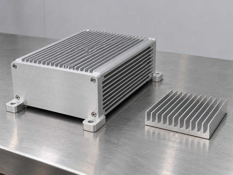
A structural aluminum heat sink has a defined mechanical role in addition to its cooling function. It may form an enclosure wall, support mounted equipment or connect the cooling assembly to a chassis. Identify that role through requirements and interfaces. The presence of thick metal or large fins does not establish an allowable load, and an ordinary cooler should not be treated as a qualified bracket without a mechanical review.
Which interfaces should appear on the drawing?
Mark the device contact pad, mounting lands, fastener locations and any surfaces that locate the part in its housing. Describe the loads and displacement limits relevant to those interfaces. If another component supports the cooler, show that support as well. This keeps the design review focused on the complete assembly instead of assuming the heat sink carries every load visible around it.
- Identify the mechanical function and supporting parts.
- Mark heat-input and load-input locations.
- Define the interfaces included in the supplied scope.
| Function | Requirement to establish |
|---|---|
| Device cooling | Heat input and temperature limits |
| Equipment support | Loads and permitted movement |
| Housing integration | Locating, fastening and sealing interfaces |
Keep the component’s structural responsibility explicit throughout the design review.
2. Which operating conditions define the design?
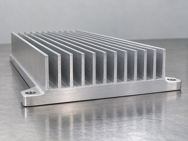
Define a structural aluminum heat sink from the thermal and mechanical conditions it must experience in service. Record heat loss and local cooling conditions alongside orientation, supported mass and relevant external forces. Installation and maintenance can introduce loads different from normal operation. Include those conditions where they affect the part, rather than using the device’s electrical rating as a complete design brief.
How should coupled conditions be reviewed?
Check which loads occur while the part is hot. Temperature can change dimensions, contact pressure and the behavior of nearby materials. A room-temperature fit check may therefore miss an operating issue. Identify the required combinations in the validation plan, and agree which conditions need analysis, a prototype test or both. The supplier needs those combinations to evaluate the same problem your assembly must solve.
- Record continuous and transient heat loss.
- Describe loads, orientation and constraints.
- Identify relevant hot-state load combinations.
| Condition | Useful input |
|---|---|
| Normal operation | Loss, local air or coolant conditions |
| Mechanical service | Supported loads and movement limits |
| Installation | Handling and fastening constraints |
Review the limiting combinations before selecting the final cross section.
3. How should material and geometry be selected together?
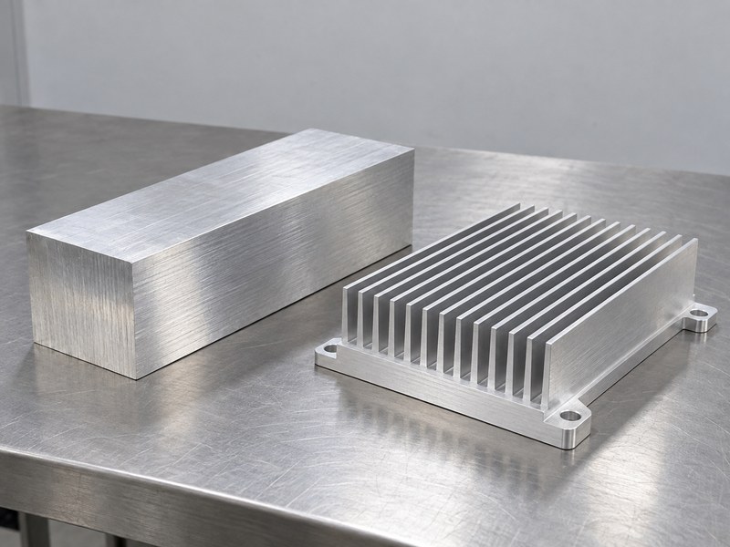
Select a structural aluminum heat sink material together with its geometry and production condition. Thermal conductivity alone does not describe stiffness, strength or manufacturing feasibility. Specify alloy and temper where those properties affect acceptance. Use data appropriate to the supplied material and process, and review how the proposed section distributes metal between the contact base, supporting walls and exposed fins.
What does a heavier section actually provide?
Additional metal can change spreading, stiffness, thermal capacity and mass at the same time. It does not guarantee a better installed cooler. A heavier part also places different loads on its mounts. Compare candidate sections against the defined heat and load paths so you can see which change addresses a requirement and which merely adds material or consumes space needed for airflow.
- Identify material properties needed for each function.
- Review the supplied alloy and temper condition.
- Compare geometry, mass and installation effects together.
| Design feature | Question for the review |
|---|---|
| Contact base | Does it support spreading and contact requirements? |
| Supporting wall | Does its section meet the mechanical need? |
| Fin array | Can the available air remove the heat? |
Choose the section from its functions rather than from weight or appearance alone.
4. How does the contact base affect both functions?
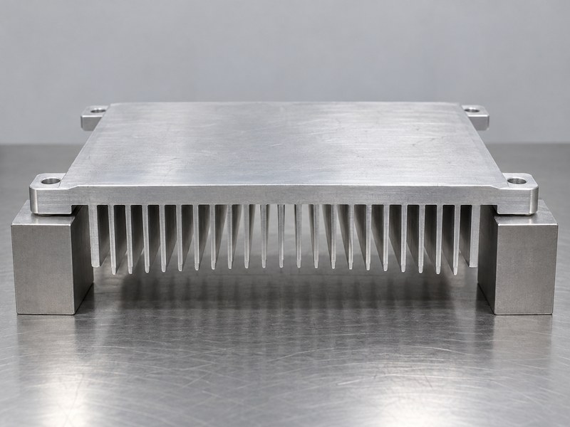
The base of a structural aluminum heat sink spreads heat and transfers mounting or clamping loads through the part. Its thickness, flatness and support arrangement can affect both functions. A contact face that bends during fastening may produce a different interface from the one measured before assembly. Define the required finished surface and the condition under which its geometry must be assessed.
Which machining details need early attention?
For CNC machined heat sinks, place the functional datums and contact requirements on the drawing before machining and finishing are planned. Identify areas that must remain uncoated or receive a controlled treatment. If the assembly relies on a pad or grease layer, review the actual gap and clamp arrangement. Surface appearance cannot establish flatness or prove that the device will contact the intended area.
- Define finished contact geometry and datums.
- Review the base under the intended assembly loads.
- Control the interface material and surface condition.
| Contact detail | Acceptance question |
|---|---|
| Flatness | In which restrained or free condition is it required? |
| Surface finish | Does it suit the intended interface? |
| Masked area | Does it cover the usable device footprint? |
Validate the assembled contact arrangement as well as the loose part.
5. Where should mounting loads enter the cooler?
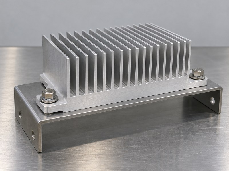
Direct mounting loads into the defined supporting features of a structural aluminum heat sink. Base ears, bosses and enclosure walls may be designed for those loads; thin fins normally need a separate assessment before they are used as attachments. Trace each force through the part and into the chassis or bracket. Include eccentricity, because a load offset from the supports can create bending as well as direct force.
What should the fastening specification control?
Review the heat sink mounting hardware with the joint geometry and the limits of the mounted device. Define engagement, seating surfaces and the assembly method. If the design uses a spring element, establish its working range and force. Do not assume that adding a fastener always improves contact; the load distribution and local deformation still need to suit the assembly.
- Identify supporting lands and force directions.
- Check fastener engagement and seating.
- Review the effect of joint loads on the device pad.
| Mounting feature | Review focus |
|---|---|
| Base ear or boss | Load path and local geometry |
| Threaded joint | Engagement and assembly control |
| Supporting bracket | Constraint and displacement behavior |
Keep fastening loads on the features evaluated for that purpose.
6. How should the structure leave room for airflow?
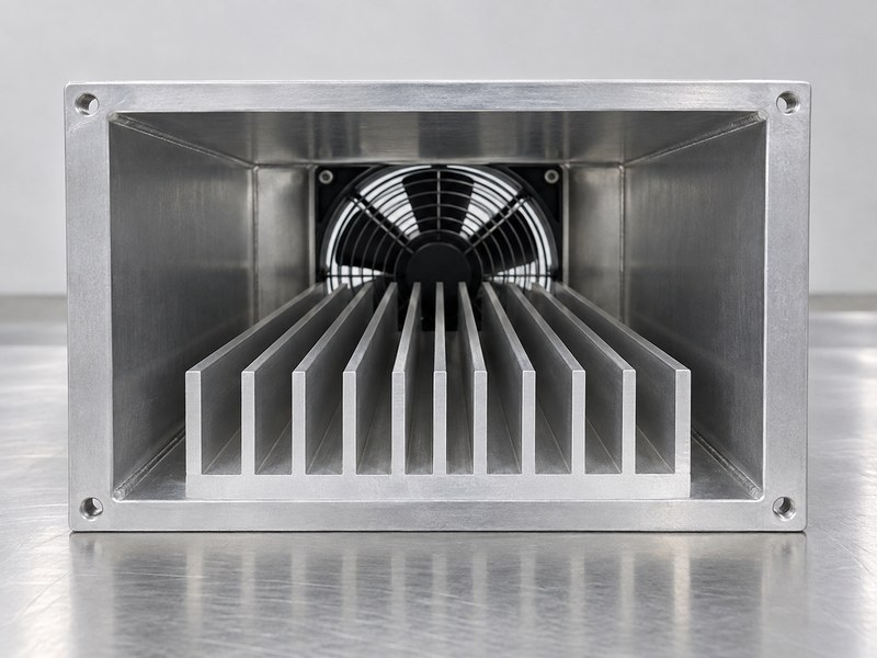
A structural aluminum heat sink needs an installed air path that can reach the cooling surfaces and leave the equipment. Supporting walls, brackets and covers can obstruct that path even when the fin geometry looks generous on its own. Review the cooler in its actual enclosure. Straight channels need an appropriate inlet and outlet, and surrounding gaps can let forced air bypass the intended fin passages.
What should be checked for passive operation?
For natural convection, review orientation, clearance and nearby warm surfaces. An integrated housing may be installed in several positions, so establish which positions are allowed. For forced airflow, evaluate the fan and system restrictions together. A free-air fan value does not establish the flow through the installed cooler, and a structural change that alters a duct can invalidate an earlier thermal comparison.
- Check inlet, channel and outlet clearance.
- Review permitted installation orientations.
- Include brackets and covers in airflow evaluation.
| Installation feature | Possible effect |
|---|---|
| Supporting wall | Blocks or redirects flow |
| Duct gap | Allows bypass around the fins |
| Nearby heat source | Raises local inlet temperature |
Repeat the relevant airflow check when the surrounding structure changes.
7. What changes when the cooler forms the enclosure?
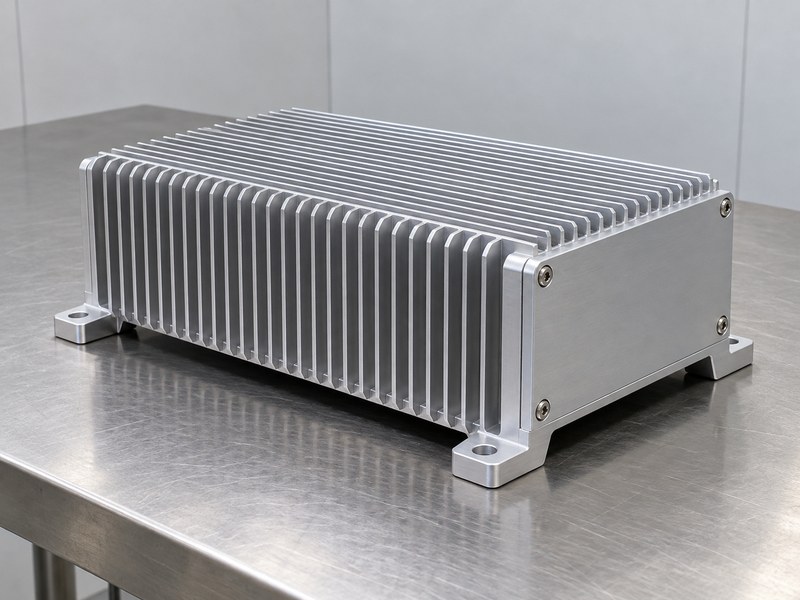
When a structural aluminum heat sink forms an enclosure, the internal components still need a defined path to the external cooling surfaces. A finned wall cannot remove heat effectively from a device that is poorly coupled to it. Locate hot components and their contact arrangements before treating the enclosure as the cooling solution. Review the mechanical and thermal effect of covers, seals and internal supports.
Which interfaces should stay independently controlled?
Keep thermal lands, electrical bonding points and sealing surfaces identified on the assembly drawing. A finish suitable for an exposed outer surface may require masking or a different treatment at those interfaces. Confirm that service access and fastening do not disturb the intended contact. An enclosure’s appearance alone does not establish a verified ingress rating or an allowable mechanical load.
- Locate internal heat sources and their contact paths.
- Mark thermal, bonding and sealing interfaces.
- Include service access in the assembly review.
| Enclosure interface | Requirement to define |
|---|---|
| Device-to-wall contact | Gap, material and clamping |
| Cover or seal land | Geometry and assembly condition |
| External mounting | Loads and allowed displacement |
Evaluate the populated enclosure rather than the empty shell alone.
8. How is a liquid cold plate different?
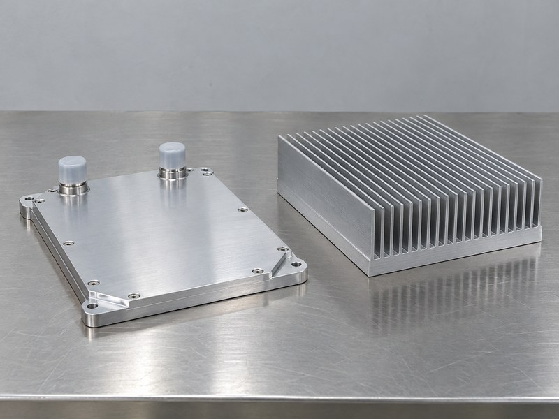
A structural aluminum heat sink that contains coolant needs additional requirements for its fluid boundary. A cold plate transfers device heat into a flowing medium, while another part of the system must reject that heat. The supporting body, cover joint, ports and seals have mechanical responsibilities beyond holding fins. Define the intended fluid, pressure and operating conditions instead of assuming a solid extrusion review also covers a coolant-bearing assembly.
Which loads belong at the fluid interfaces?
A friction stir welded cold plate needs a joining and inspection plan appropriate to the application. Include fitting engagement and hose or tube loads where they affect the ports. Keep thermal, dimensional and containment acceptance separate. A successful leak check under stated conditions does not establish fatigue life, and a good temperature result does not prove fluid integrity.
- Define the complete coolant boundary.
- Identify loads at ports and supports.
- Separate thermal and containment evidence.
| Cold-plate feature | Requirement to review |
|---|---|
| Joined cover | Integrity and finished geometry |
| Port | Fitting interface and external loads |
| Device land | Contact and thermal performance |
Assign responsibility for each interface when the loop uses components from several suppliers.
9. How should the prototype be validated?
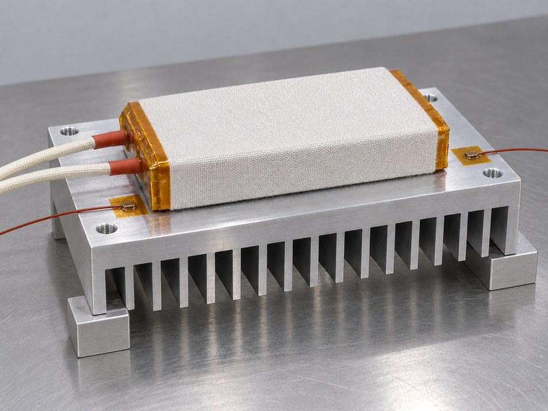
Validate a structural aluminum heat sink in the configuration that carries the required loads and dissipates the specified heat. Record its mounting, contact material and local cooling conditions. Check the mechanical and thermal properties affected by the required test sequence. If a mechanical exposure can change the joint or contact face, the thermal check after that exposure may be as useful as the initial result.
What should the test record identify?
Identify the part revision, fixture, load conditions and measurement locations. Use package-appropriate thermal metrics when relating a measured surface point to a device temperature estimate. State the acceptance limits and measurement uncertainty relevant to the decision. Keep calculated predictions, observed results and supplier assumptions distinguishable so a reviewer can assess what the prototype actually demonstrated.
- Test the relevant combined operating conditions.
- Record the complete contact and mounting arrangement.
- Recheck functions affected by the exposure sequence.
| Validation evidence | Purpose |
|---|---|
| Mechanical result | Assesses the defined load and movement requirement |
| Thermal result | Assesses the specified heat and cooling condition |
| Post-test inspection | Detects joint or geometry changes |
Retain enough setup detail to repeat the accepted configuration.
10. What should you include in a supplier RFQ?
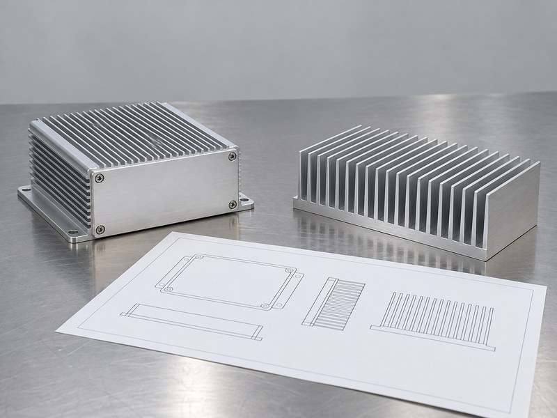
A structural aluminum heat sink RFQ should contain the functional drawing, thermal brief and mechanical requirements together. Identify critical interfaces, material condition, finishing and required inspection evidence. Define whether the supplier provides a loose component, a populated enclosure or a coolant-bearing assembly. Those boundaries determine which performance claims and records belong in the quotation.
Which assumptions should be resolved before release?
Ask the supplier to identify missing inputs, proposed manufacturing allowances and exclusions. Agree on the prototype configuration and acceptance plan before releasing production tooling. Keep changes to wall geometry, mounting features and contact faces under the same review process as changes to the cooling section. A late mechanical alteration can affect a thermal result that was previously acceptable.
- Supply the final interface drawing and load brief.
- Define the thermal conditions and acceptance limits.
- Agree on prototype and production evidence.
| RFQ item | Decision it supports |
|---|---|
| Functional drawing | Locates supporting and contact features |
| Thermal brief | Defines heat input and cooling boundaries |
| Validation plan | Defines what the prototype must demonstrate |
Send those requirements when you contact us so the component review covers both cooling and mechanical integration.
Frequently asked questions
Q1: Can a heat sink also support equipment?
Yes, when its mechanical function has defined requirements and suitable validation. Do not infer an allowable load from size or appearance.
Q2: What’s the best place for mounting holes?
Use features designed for the joint loads and assembly constraints. Review thick base lands, bosses and their effect on the device contact face.
Q3: How do I know whether the base is stiff enough?
Assess deformation under the required loads and constraints. Check the consequence for contact, fit and sealing rather than relying on thickness alone.
Q4: Can external fins cool a sealed enclosure without a fan?
Only if the complete internal-to-external heat path meets the temperature limits under the required conditions. Validate the populated assembly.
Q5: Does a leak test qualify a structural cold plate?
No. Containment, mechanical behavior and thermal performance need the separate evidence required by the application.