
Choose an insulated heat sink by defining the electrical boundary and verifying the complete mounted thermal path. An RFQ note such as “anodize heat sink for insulation” leaves the device potential, fasteners and acceptance conditions unresolved. A coated sample can look satisfactory while the assembled hardware creates another conductive path. Use device documentation and application-specific assembly evidence to close those gaps before approving a production interface.
1. What must an “anodize heat sink for insulation” note define?
The note “anodize heat sink for insulation” must identify which conductive parts need separation and why. Functional isolation supports correct circuit operation; protection against electric shock requires the appropriate safety-insulation design. The equipment’s responsible electrical engineer should define the boundary before a finisher receives a coating request.
Which questions belong in the electrical interface brief?
Identify the device mounting surface, heat sink, chassis and any accessible conductive hardware. Before choosing a finish, state the operating environment and what each boundary must do. Include both normal operation and the fault conditions that the equipment design must address. This gives the thermal team a defined boundary to preserve while it selects contact materials, mounting features and cooling geometry.
- Name the conductive regions being separated.
- State the purpose of each insulation boundary.
- Assign responsibility for electrical acceptance.
| Interface question | Requirement to define |
|---|---|
| Which parts can differ in potential? | Electrical boundary |
| What protection is required? | Insulation function |
| Who accepts the assembly? | Responsible design authority |
Replace the short finish note with an interface requirement the drawing can express.
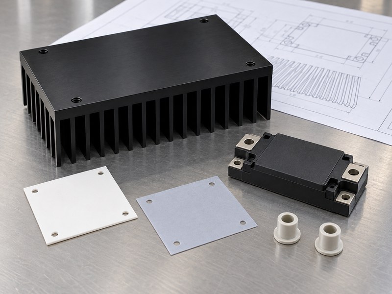
2. How do you identify the electrical potential of a device tab?
Read the exact device’s package and electrical documentation to establish its mounting-tab or baseplate potential. For “anodize heat sink for insulation,” that information determines which separation the mounting stack must provide. Some power-device tabs connect electrically to a circuit terminal while some packages contain internal isolation. Similar-looking packages can have different electrical structures, so appearance cannot settle the question.
What should you check when several devices share one sink?
Create a potential map for every mounted device and the surrounding metalwork. In industrial power supplies, nearby switches and rectifiers may connect with different circuit nodes even when they share a thermal structure. Because variants can use different internal connections, check the exact part and package instead of relying on a family name. Keep the accepted device list with the mounting drawing so a substitution triggers an electrical and thermal review.
- Identify each tab or baseplate connection.
- Record internally isolated package variants accurately.
- Review substitutions before accepting equivalent footprints.
| Device information | Design implication |
|---|---|
| Tab connected with a terminal | Review potential relative to the sink |
| Internally isolated base | Check its documented conditions |
| Multiple mounted devices | Review every shared-metal boundary |
Keep the electrical map attached to the heat-source layout.
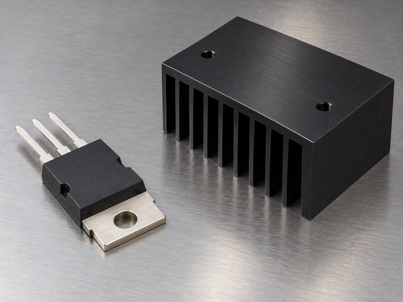
3. Why can oxide coverage leave an incomplete insulation path?
Local defects, exposed edges and adjacent metal can interrupt the boundary assumed from a coated surface. A request to “anodize heat sink for insulation” needs review of actual coverage and the complete assembly geometry. A flat test coupon does not represent every bore, edge or rack-contact location on a finished part. Because handling can damage an inspected surface, include assembly and service exposure in the review.
Which locations deserve attention beyond the broad face?
Review hole edges, masking boundaries, machining transitions and areas contacted during assembly. Include contaminants or burrs that could damage an added insulating sheet. Check the shortest relevant paths around the barrier as well as through its material. Increasing nominal oxide thickness on an accessible flat region cannot establish what happens at a different location that the inspection plan never examines.
- Identify intentional and incidental exposed metal.
- Specify surface preparation around the interface.
- Inspect locations that represent the proposed boundary.
| Location | Question for review |
|---|---|
| Coating edge | Is the intended separation continuous? |
| Hole or recess | What coverage and inspection are practical? |
| Contact face | Could damage affect an added barrier? |
Match inspection coverage with the geometry carrying the electrical requirement.
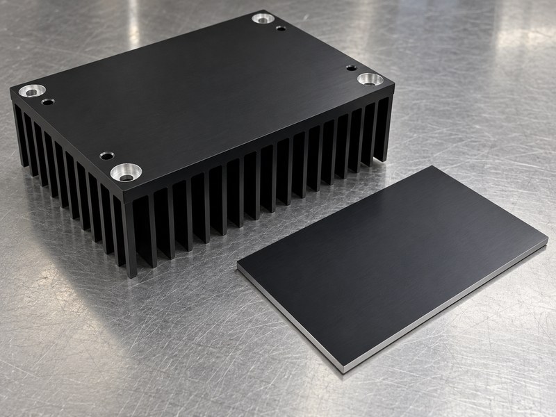
4. How can screws and washers bypass the intended barrier?
A conductive fastener can connect metal regions around an insulating layer if the mounting design permits contact. Interpret “anodize heat sink for insulation” across the fastener, hole wall, washer and adjacent device surfaces. A pad beneath the device addresses only part of that geometry. An insulating washer on one face cannot establish the electrical behavior of the entire fastening path.
What belongs in a coordinated mounting-hardware review?
Review heat sink mounting hardware as a controlled set matched to the package and interface. Where sleeves or shoulder bushings are proposed, check their fit, seating and permitted loading with the device supplier. Include movement and tolerance stack-up that could bring conductive surfaces into contact. Although a parts list may include plastic hardware, the assembled insulation system still needs its own approval.
- Identify all conductive fastener contact surfaces.
- Control the complete mounting stack and tolerances.
- Review the assembly after representative loading.
| Mounting element | Boundary concern |
|---|---|
| Screw and hole | Possible metal contact along the shaft |
| Washer or clip | Contact with neighboring conductive regions |
| Insulating bushing | Fit, seating and mechanical stability |
Approve the hardware combination rather than separate component appearances.
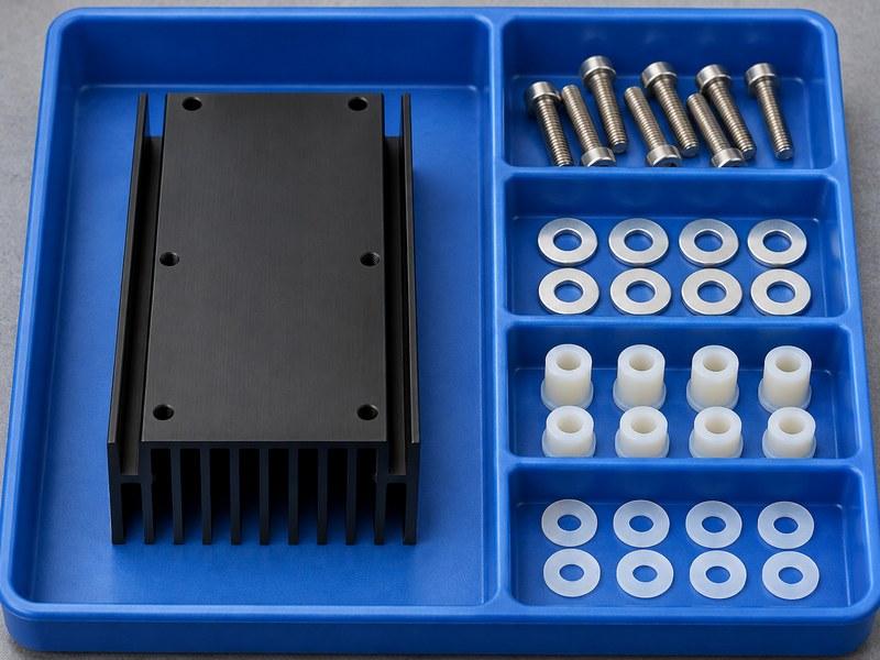
5. When should you consider a separate insulating interface?
Consider a separate interface when the electrical boundary requires a qualified material or construction beyond the specified finish. The requirement “anodize heat sink for insulation” can lead to a ceramic sheet, an electrically insulating polymer interface or an internally isolated device package. A material name or catalog breakdown value cannot approve the completed mounting assembly.
How should you compare the available material systems?
Compare thermal impedance, required thickness, contact area, mechanical behavior and documented electrical performance. Because a rigid ceramic sheet and a soft polymer pad behave differently, review their mounting constraints separately. Some thermal interface materials conduct electricity, so verify electrical properties instead of assuming every heat-transfer sheet provides isolation. Review the selected shape, cutouts and surrounding hardware together with the material supplier and equipment designer.
- Use the exact material grade and configuration.
- Check permitted surface and mounting conditions.
- Preserve the approved package and hardware combination.
| Interface route | Evidence to request |
|---|---|
| Ceramic sheet | Material data and supported assembly geometry |
| Polymer interface | Electrical and thermal data under relevant conditions |
| Isolated device package | Package-specific isolation and mounting information |
Select a documented system that the assembled equipment can verify.
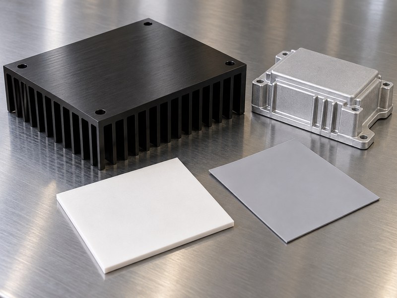
6. Can “anodize heat sink for insulation” coexist with bonding?
Yes, the design can define separate isolation regions and intentional conductive bonding regions. A drawing marked “anodize heat sink for insulation” should identify the metal that needs bonding and the interfaces that require separation. A broad instruction to coat everything can conflict with an intended conductive contact or leave its acceptance ambiguous.
How should those regions appear on the drawing?
Use a surface map with controlled boundaries and identify the associated mounting features. For a heat sink enclosure, consider internal device interfaces, chassis connections and accessible housing surfaces in the same review. A masked contact land should serve its documented purpose without bridging an adjacent isolation region. Keep approved bonding hardware and surface treatment with the electrical assembly definition.
- Identify isolation and bonding regions separately.
- Dimension functional surface boundaries.
- Review nearby screws, clips and enclosure contacts.
| Region | Required function |
|---|---|
| Device isolation area | Preserve the defined electrical separation |
| Conductive contact land | Support its approved bonding connection |
| Surrounding structure | Maintain the required interface geometry |
Check the installed assembly against both functions before releasing the surface map.
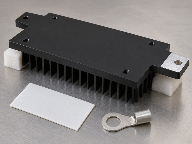
7. How do humidity, aging and mounting pressure change the review?
Review the interface after the environmental and mechanical conditions it must withstand. Treat “anodize heat sink for insulation” as a requirement for the service environment rather than a description of a new, dry sample. Moisture response depends on the actual material system. Mounting pressure and thermal cycling can change contact conditions, and excessive local loading can damage an insulating interface.
Which conditions should the qualification plan represent?
Provide the required humidity, temperature cycling, service handling and installed loading conditions to the responsible engineer. Ask material suppliers for relevant conditioned data and its test limitations. Include repeated assembly only when the equipment’s service plan permits it. Because exposure can change the interface, check the barrier, hardware and thermal contact after the required conditioning.
- Define exposure and installed mounting conditions.
- Review interface damage and contamination risks.
- Check the assembly after representative conditioning.
| Service condition | Evidence needed |
|---|---|
| Humidity exposure | Relevant conditioned electrical behavior |
| Thermal cycling | Interface and mounting stability |
| Maintenance handling | Approved replacement or reuse conditions |
Keep conditioning requirements tied to the same assembly revision as the electrical checks.
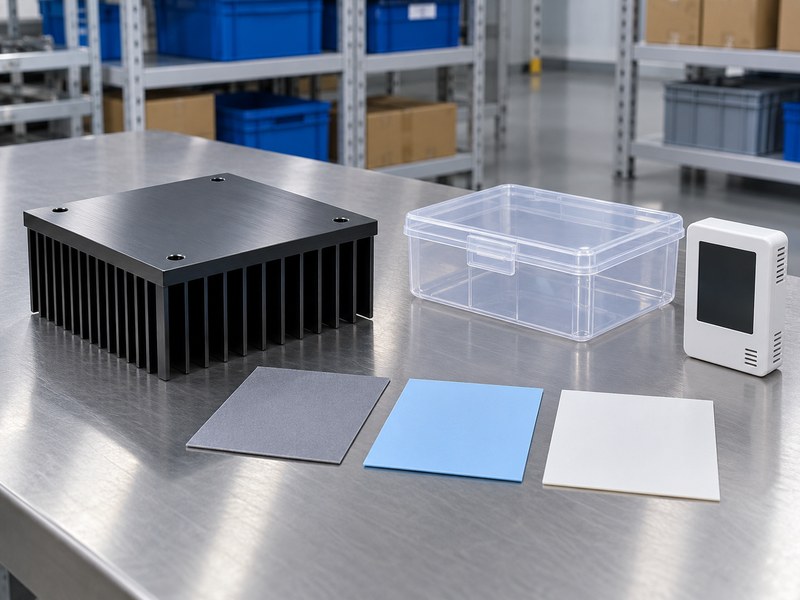
8. How should insulation and thermal resistance be balanced?
Balance the electrical requirement with the complete device-to-sink thermal path at permitted mounting conditions. The note “anodize heat sink for insulation” leaves that temperature allowance undefined. Added material contributes its own thermal resistance and creates contact interfaces on either side. Material conductivity alone cannot predict the assembled temperature when thickness, surface condition and contact pressure remain unspecified.
Which thermal data should you compare?
Use thermal impedance data whose test conditions represent the proposed interface, then verify the assembled device temperature at the intended losses. Keep package resistance, interface resistance and sink-to-environment performance separate in the model. Although a thermal curve may favor more pressure, it does not set the assembly’s safe mounting load. Verify dielectric behavior within the device and interface suppliers’ permitted load range.
- Record material thickness and contact area.
- Use the permitted mounting-load range.
- Verify both electrical and thermal acceptance.
| Heat-path term | Input needed |
|---|---|
| Device package | Documented thermal reference |
| Insulating interface | Material and assembled contact conditions |
| Heat sink | Actual cooling boundary |
The conceptual curve below illustrates contact-related thermal resistance only; it contains no measured results or electrical qualification data.
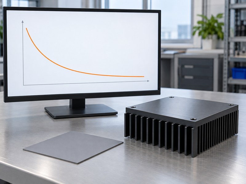
9. Which tests belong to the conditioned mounting assembly?
The complete interface needs the electrical and thermal checks selected for its defined function and equipment requirements. For “anodize heat sink for insulation,” a coating-thickness report or isolated material test is incomplete evidence. The responsible engineer should specify applicable insulation-resistance, dielectric-withstand and bonding checks. Their conditions and acceptance limits must follow the actual design, with qualified personnel controlling the test procedure.
What should the approval record identify?
Record the device variant, heat-sink revision, interface grade, hardware and relevant conditioning. Identify which electrical boundary each result addresses and whether the test article represents the intended assembly. If conditioning can change the interface, repeat the thermal check afterward. A test result belongs with its documented construction and conditions; it cannot authorize an unreviewed material or fastener substitution.
- State the assembly and conditioning covered.
- Record methods and acceptance limits set by engineering.
- Keep results traceable to the approved construction.
| Evidence | Question it answers |
|---|---|
| Material data | What properties does the selected material report? |
| Assembly electrical checks | Does the defined boundary meet its requirements? |
| Assembly thermal checks | Does the accepted construction retain temperature margin? |
Approve the evidence for the assembled interface and its intended environment.
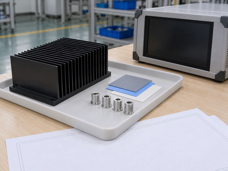
10. What should purchasing require before accepting the interface?
Require a released interface drawing, controlled bill of materials and defined acceptance evidence. An order marked “anodize heat sink for insulation” needs the device, finish, interface material and hardware identified together. A supplier’s coating certificate may support process control, but it cannot replace the equipment designer’s acceptance of the complete electrical interface.
Which substitutions and changes should trigger review?
Define the review process for changes in device package, pad grade, cutout shape, bushing, finish or mounting arrangement. Keep service replacement instructions aligned with the approved construction so maintenance does not introduce another material. Before approving samples, ask suppliers to identify any unresolved assumptions. Purchasing then has a basis for rejecting a substitution that looks similar while changing thermal contact or the electrical path.
- Attach the electrical and thermal interface definition.
- Specify approved materials and mounting components.
- Define acceptance records and change notification.
| Purchase item | Information to preserve |
|---|---|
| Interface drawing | Electrical regions, geometry and finish |
| Controlled parts list | Device, material grade and hardware |
| Acceptance package | Conditioned electrical and thermal evidence |
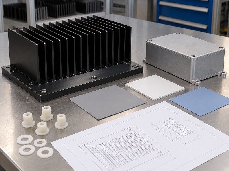
Send your device documentation, interface drawing and operating environment when you contact us. Request a joint review of the thermal path and the electrical requirements assigned by your equipment designer.
FAQ
Q1: Can I use a material’s breakdown number as its operating rating?
No. A breakdown result belongs to stated test conditions. Have the responsible engineer establish the permitted use and required verification for the actual assembly.
Q2: What’s the best insulating material for my heat sink?
Choose against the defined electrical boundary, temperature budget and mounting conditions. Ceramic, polymer and internally isolated package routes need different supporting evidence.
Q3: How do I know if an insulating washer is enough?
Review the entire fastening path. The screw shaft, device tab, hole wall and nearby metal can create contacts outside the washer’s area.
Q4: Can I replace a separate pad with thicker anodizing?
Only through a reviewed and verified design change. Extra coating thickness does not establish equivalent electrical, mechanical or thermal behavior.
Q5: Can I reuse an insulating pad after servicing?
Follow the approved service procedure. Removal can change the material or contact condition, so reuse needs support from the selected interface system and assembly validation.