
A voltage regulator heat sink carries heat from a regulator package into surrounding air. You choose it by calculating power loss and allowable temperature rise, then checking mounting, insulation and airflow. A supply that works on an open bench can overheat inside its enclosure, so the final assembly needs its own thermal check.
1. When does a voltage regulator heat sink become necessary?
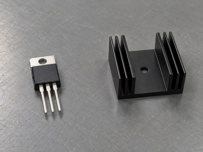
A voltage regulator heat sink becomes necessary when the package and board cannot keep junction temperature below your design limit under the intended load. Rated output current alone cannot answer that question. Input voltage, output voltage, local air temperature and the thermal path all change the result.
Check the operating point
For a linear regulator, voltage dropped across its pass element creates heat. Reducing 12 V to 5 V at 0.5 A produces approximately 3.5 W before quiescent-current loss, while reducing 7.5 V to 5 V at 0.1 A produces about 0.25 W. These are calculation examples, rather than ratings for a particular regulator, and neither tells you junction temperature until you add thermal resistance.
- Record maximum sustained input voltage and load current.
- Include the air temperature beside the regulator.
- Check startup, overload and enclosure conditions separately.
Set an acceptance limit
Choose a junction-temperature target below the selected device’s allowed operating maximum. Thermal shutdown protects against certain fault conditions; cycling into shutdown during normal service signals an unfinished design. Keep the electrical operating limit and your reliability margin visible in the review.
| Input to the decision | What you need |
|---|---|
| Heat generation | Worst sustained device loss |
| Cooling conditions | Local air temperature and orientation |
| Acceptance | Junction target with stated margin |
These three inputs determine whether extra cooling has a measurable job.
2. How do you calculate the required thermal resistance?
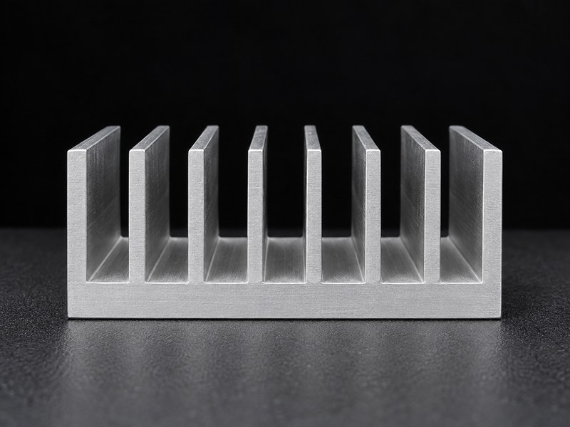
The required voltage regulator heat sink resistance is the remaining thermal budget after package and interface resistance. A common steady-state screening equation is RθSA ≤ (TJ,target − TA)/PD − RθJC − RθCS. Use the junction-to-case value for the surface that actually connects with your sink.
Keep the assumptions visible
Suppose a design dissipates 3.5 W, operates in 45°C local air and uses a 110°C junction target. If its applicable junction-to-case resistance is 4°C/W and interface resistance is 1°C/W, the sink allowance is about 13.6°C/W. Those assumed package and interface values must be replaced with documented values for your assembly before purchasing a part.
- Match each resistance with its physical surface.
- Use watts for loss and degrees Celsius per watt for resistance.
- Avoid adding a complete junction-to-ambient rating to the series path.
Read the result correctly
A lower allowable RθSA demands stronger cooling under the stated conditions. A negative result means package and interface drops already consume the temperature budget, even with an ideal sink in this simplified model. Revisit loss, temperature limits or package selection before enlarging fins.
| Budget item | Example assumption |
|---|---|
| Permitted junction rise | 65°C |
| Total allowable resistance | 18.6°C/W |
| Package plus interface | 5°C/W |
| Remaining sink allowance | About 13.6°C/W |
The calculation specifies a performance requirement, rather than a physical size.
3. Which mounting details control heat transfer?
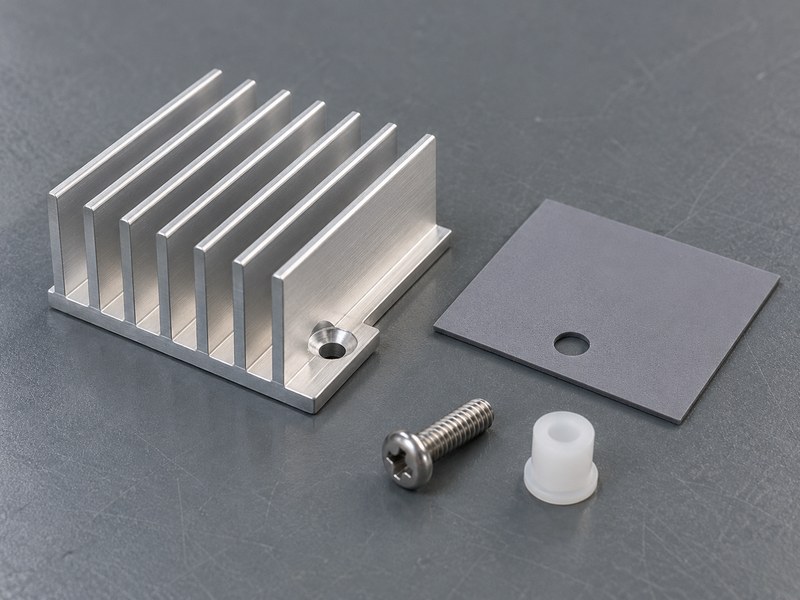
Mounting details control how consistently a voltage regulator heat sink contacts the intended package surface. Flatness, pressure, interface thickness and hole location belong in the drawing. A loosely attached part can have enough fin area yet still run hot at its junction.
Match the package surface
Check the component manufacturer’s recommended mounting arrangement before choosing screws or clips. A TO-220 tab offers a different mechanical path from an exposed pad soldered beneath a surface-mounted regulator. Pressing a sink against the molded top of a small package may provide little benefit if the device mainly transfers heat through its board attachment.
- Keep burrs and raised edges outside the contact area.
- Specify the interface material and assembled thickness.
- Support the sink without loading component leads.
Control assembly pressure
Follow the package and hardware suppliers’ limits for torque or clip force. Extra torque can bow a tab, damage insulation or stress the package; it does not guarantee better contact. Select a process that assemblers can repeat and inspectors can verify after the unit has completed its environmental tests.
| Mounting feature | Acceptance evidence |
|---|---|
| Contact face | Flatness and surface condition |
| Fastening | Approved torque or clip force |
| Interface | Correct material and coverage |
A repeatable assembly process makes sample thermal results useful for production.
4. Does the regulator need electrical isolation?
Electrical isolation is required when a voltage regulator heat sink would otherwise connect a live package surface with an incompatible conductor or accessible chassis. Read the exact part’s pin and tab connection. Similar-looking three-pin packages can place ground, output or another electrical node on their exposed metal.
Trace every conductive route
An insulating pad beneath the tab may leave a conductive path through the mounting screw. Use the specified shoulder washer, insulated fastener or mounting system where needed, and inspect its orientation. Black anodizing should not be your sole electrical safety barrier because holes, cut edges, defects and assembly wear can expose conductive aluminum.
- Identify tab potential for each device variant.
- Include screws, clips and mounting rails in the check.
- Define the required electrical test for the product.
Include the thermal penalty
An electrically insulating interface adds thermal resistance and may change the required sink size. Compare candidate materials at their intended thickness and pressure, with appropriate voltage and environmental ratings. Electrical acceptance and thermal acceptance need the same final stack of parts.
| Potential short path | Item to inspect |
|---|---|
| Tab to base | Insulating interface |
| Screw to tab | Shoulder insulation where required |
| Sink to chassis | Intended bonding arrangement |
Approve the full mounting stack before assigning it a thermal rating.
5. How should you choose material and fin geometry?
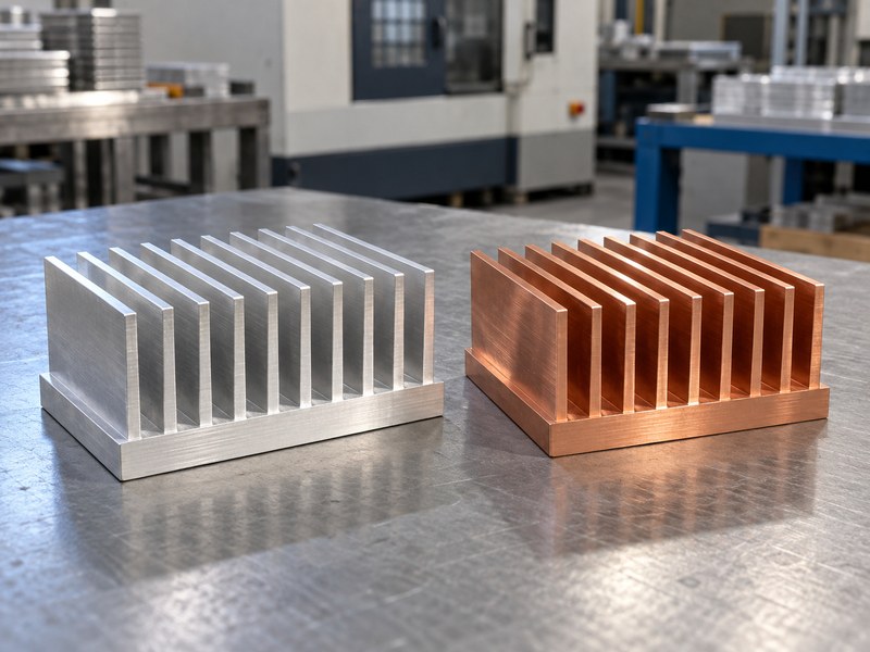
Choose voltage regulator heat sink material and geometry around heat spreading, available space, airflow and production needs. Copper can help spread concentrated heat, while aluminum often suits lightweight extruded parts. Neither material guarantees a lower assembly temperature without the right contact area and air-side surface.
Compare workable constructions
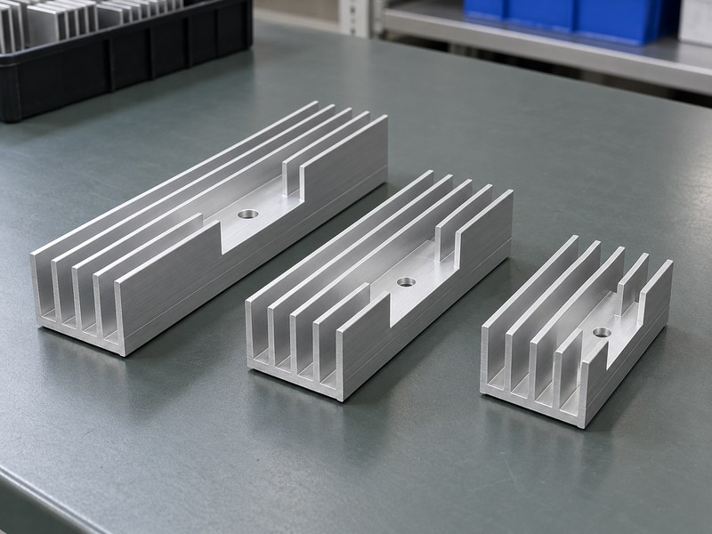
For a compact regulator, an existing extrusion with drilled mounting holes can avoid unnecessary tooling. A custom contact pattern or tight mechanical envelope may justify CNC machined heat sinks. Ask suppliers to compare complete designs under the same mounting orientation and cooling conditions, instead of comparing conductivity numbers alone.
- Check base spreading beneath the small package footprint.
- Leave fin channels open at both ends.
- Include coating and machining tolerances in the finished dimensions.
Keep the fins usable
Closely spaced fins add area but can restrict natural convection or collect contamination. A taller part may collide with a cover or block nearby components. Select a geometry that fits the installed assembly and its cleaning or maintenance requirements.
| Design choice | Practical tradeoff |
|---|---|
| Aluminum extrusion | Profile availability and low mass |
| Copper construction | Spreading performance and weight |
| Dense fins | Added area and airflow restriction |
Compare the full geometry before assigning value to any one material property.
6. How does airflow change the selection?
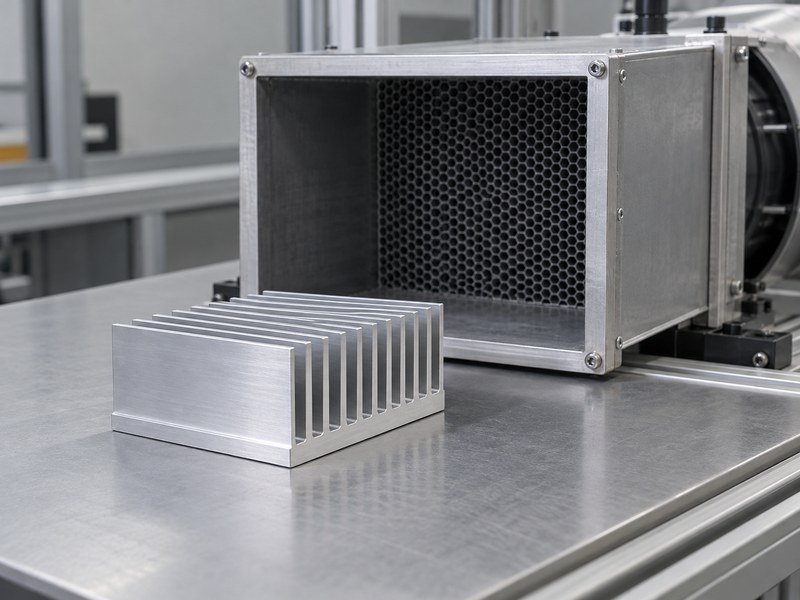
Airflow changes the voltage regulator heat sink’s resistance between its surface and surrounding air. A rating measured with forced flow may be unsuitable in a sealed or fanless enclosure. Obtain the supplier’s conditions for orientation, airflow, heat input and temperature rise before comparing catalog figures.
Follow the installed air path
The fan’s free-air rating does not describe flow through your fin channels. Filters, grilles, cable bundles and competing branches can reduce or divert that flow. Align the channels with the intended air path and check whether air passes through the sink rather than taking an easier route around it.
- Measure local inlet air after neighboring heat sources.
- Test with the intended filter and cover installed.
- Review fan degradation or failure where the application requires it.
Check passive orientation
Natural convection depends on buoyancy and an available path for warmer air to leave. Rotating a board or adding a nearby cover can change that path. Keep the real orientation in thermal tests and avoid transferring a vertical-fin result to a horizontal installation without verification.
| Operating condition | Evidence to request |
|---|---|
| Fanless | Rating in the installed orientation |
| Forced air | Flow through the fin passages |
| Enclosed | Local inlet and exhaust temperatures |
Use the cooling condition your customer will operate, including its expected restrictions.
7. Can the enclosure help remove heat?
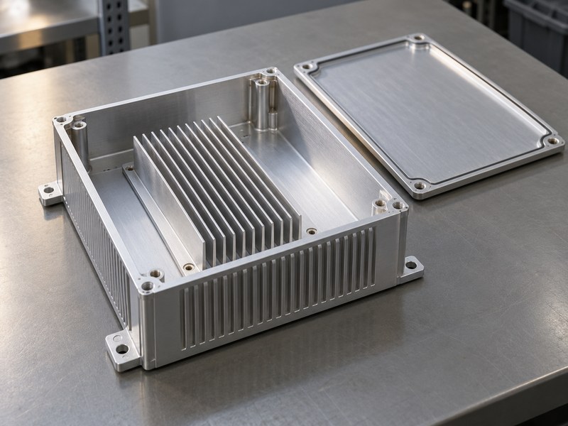
An enclosure can help a voltage regulator heat sink remove heat when the design provides a deliberate conductive path into a surface that can reject it. A sink resting in a closed box mostly heats internal air. The enclosure wall, interface and external surroundings determine whether chassis cooling adds useful capacity.
Design the heat path
An integrated heat sink enclosure needs controlled contact between the heat source and enclosure structure. Include wall thickness, spreading distance, mounting pressure and insulation in the model. A decorative metal housing with a large air gap should not receive the same thermal credit as a measured conductive joint.
- Locate the contact near a suitable external surface.
- Check touch-temperature requirements for accessible metal.
- Include all other heat sources inside the box.
Preserve assembly access
Check that installers can tighten the joint without twisting a board or trapping a cable. Service removal should not tear an insulating pad or leave the regulator unsupported. Document replacement materials so a repaired product retains its original thermal and electrical stack.
| Enclosure feature | Review question |
|---|---|
| Conductive joint | Is pressure controlled? |
| External surface | Can it release the combined heat? |
| Service access | Can insulation survive maintenance? |
The enclosure becomes part of the cooling system only when its heat path is defined.
8. How do you verify the design on a prototype?
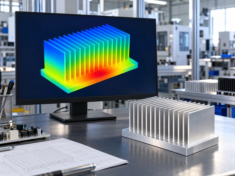
Verify a voltage regulator heat sink by testing the complete prototype at defined electrical and environmental conditions. Record input voltage, output current, local air temperature and measured case or sink temperatures together. A cool-looking thermal image alone cannot establish junction temperature or explain which operating condition produced it.
Match measurement with the model
Use a sensor location and thermal metric appropriate for the package. Case-to-junction estimation needs the applicable resistance and heat-flow assumptions; top-of-package characterization parameters have a different purpose. For infrared inspection, address surface emissivity and reflections, particularly on bare metal, and compare uncertain readings with a suitable contact measurement.
- Test sustained load until temperatures settle.
- Record sensor attachment and measurement location.
- Repeat the test with the enclosure closed.
Investigate the hot joint
If a regulator case runs much hotter than the adjacent sink base, examine the package path and interface before adding fins. If both are hot, review sink-to-air performance, inlet temperature and total loss. A qualitative temperature map can guide inspection but still needs measured boundary conditions.
| Observation | Investigation |
|---|---|
| Large case-to-base rise | Contact and interface path |
| Hot base and fins | Air-side cooling and total loss |
| Temperature cycling | Protection action or changing load |
Use measurements to identify the resistance that needs changing.
9. What should an OEM include in a supplier request?
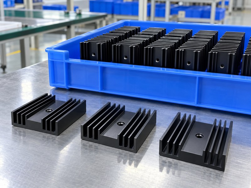
An OEM should specify voltage regulator heat sink performance, geometry and assembly conditions in the same request. A drawing with outer dimensions but no heat load leaves suppliers guessing. Include your thermal budget and package contact details so alternative proposals can be compared against one acceptance method.
Send an application record
For extruded heat sinks, identify the usable envelope, mounting face and permitted machining operations. State the expected quantities and whether the profile must remain available for repeat orders. Separate requirements you have measured from assumptions that still need prototype confirmation.
- Supply device identification and contact footprint.
- State heat loss, local ambient and airflow conditions.
- Attach dimensional and electrical insulation requirements.
Agree on sample acceptance
Define inspection points for hole position, contact flatness, finish and interface material. Thermal acceptance should identify the assembly, power input, orientation and temperature limit. Record any approved changes to the profile or coating so later orders do not silently alter the validated configuration.
| RFQ information | Why the supplier needs it |
|---|---|
| Thermal budget | Performance target |
| Contact drawing | Mounting and spreading design |
| Sample test | Comparable acceptance evidence |
A complete request reduces the chance of approving a mechanically correct but thermally unsuitable part.
10. Which checks should you complete before ordering?
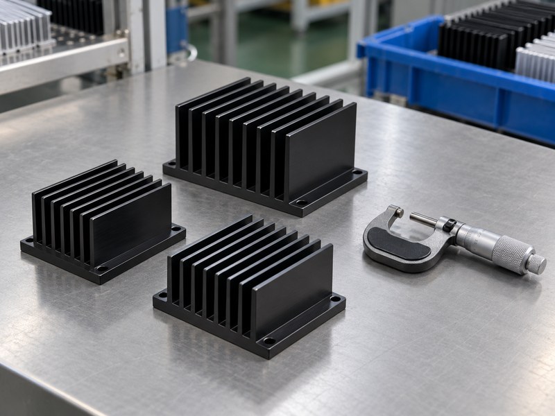
Before ordering a voltage regulator heat sink, confirm the loss calculation, installed cooling conditions, electrical isolation and prototype results. Also check that the approved materials and fastening process appear on production documents. A successful sample gives useful evidence only if production can reproduce its assembly.
Release the tested configuration
Keep the supplier drawing, interface specification and assembly instruction together. Changing a pad thickness, fastener or surface finish can change contact behavior even when the sink looks identical. If a later electrical revision increases current or input voltage, recalculate the heat load before carrying over the old approval.
- Freeze the tested mechanical and interface revisions.
- Record the operating envelope and acceptance temperatures.
- Define which changes trigger another thermal check.
Prepare the next design review
Send your package drawing, power loss, local air temperature and available envelope when you contact us. Those inputs let us discuss a suitable board-level part, extrusion or machined mounting arrangement with you. Use the agreed prototype test to decide which proposal is ready for production.
| Release check | Required record |
|---|---|
| Thermal | Calculation and prototype result |
| Electrical | Approved insulation arrangement |
| Manufacturing | Drawing and assembly revision |
Release the part against documented conditions so future orders have a clear acceptance basis.
Q1: Can I choose a sink from the regulator’s current rating?
No. Current rating omits the voltage drop and cooling conditions. Calculate device loss and junction temperature for the intended operating point.
Q2: What’s the best interface for an insulated tab?
The suitable interface meets your electrical, thermal and mechanical requirements together. Compare approved materials at the intended thickness and pressure.
Q3: How do I know if the sink is too small?
Compare estimated junction temperature with your design target during the worst sustained condition. Check contact resistance and airflow before blaming outer dimensions.
Q4: Can I reuse the same sink after changing the regulator?
Possibly. Recheck package geometry, tab potential, thermal metrics and power loss for the replacement device before retaining the assembly.
Q5: Can a cold plate replace passive fins?
Yes, when the application supports liquid cooling. The coolant temperature, flow, connection reliability and complete system cost need their own design review.