
A voltage regulator heat sink calculation converts device power loss and an allowed junction-temperature rise into a maximum sink-to-air thermal resistance. Calculate the electrical loss, subtract package and interface temperature drops, then choose a sink rated for your installed conditions. This gives you a defensible starting point before prototype testing.
1. What does a voltage regulator heat sink calculation predict?
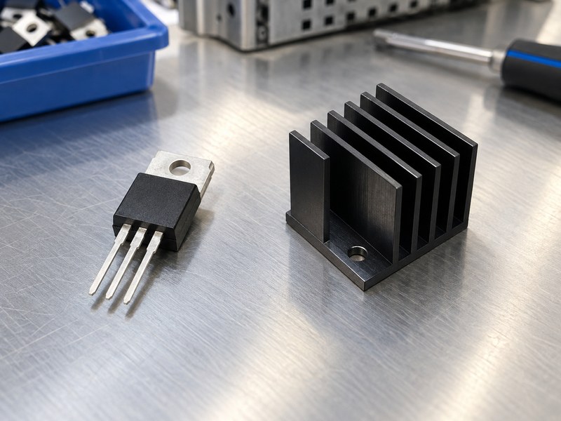
A voltage regulator heat sink calculation predicts a temperature rise for stated power and thermal-path assumptions. It can also tell you the maximum allowable sink resistance. It cannot establish a physical size without a supplier’s geometry and operating-condition data.
Draw the physical heat path
For a tab-mounted linear regulator, a useful screening model follows heat from junction through package, interface and sink into local air. A small surface-mounted regulator may send substantial heat through PCB copper instead, so a tab-mounted model would misrepresent its construction. Identify the actual contact surface before selecting thermal values from a datasheet.
- Mark the junction-to-contact surface path.
- Separate the mounting interface from the sink-to-air path.
- Identify parallel board or chassis paths that the model omits.
Define what the result means
The common series model assumes steady operation and treats each resistance as an approximation over its relevant conditions. Use it to screen parts and identify sensitivities. When a small temperature margin depends on an uncertain interface or airflow value, the next step is better evidence, rather than extra decimal places.
| Calculation output | Proper use |
|---|---|
| Junction-temperature estimate | Compare with a design target |
| Maximum RθSA | Screen candidate heat sinks |
| Sensitivity | Decide what needs measurement |
Keep the model’s boundary conditions beside its answer.
2. How do you calculate a linear regulator’s heat loss?
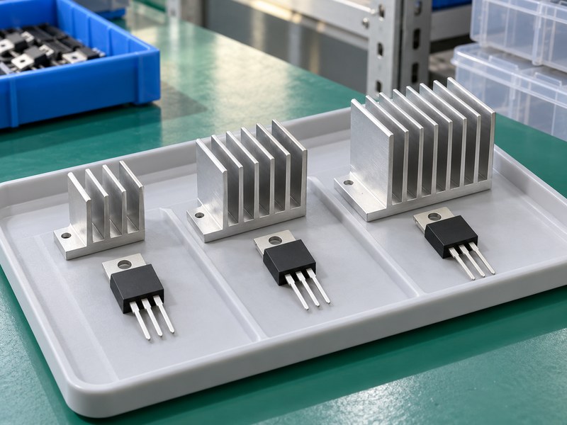
A voltage regulator heat sink calculation for a linear device starts with PD ≈ (VIN − VOUT) × IOUT + VIN × IQ. Use the selected part’s applicable ground or quiescent-current definition. The shorter approximation omits the final term only when its contribution is acceptably small.
Use the real voltage across the device
Consider an illustrative 9 V input, 5 V output and 0.5 A load. The main loss is 2 W; if input-related quiescent current is assumed to be 5 mA, its contribution is 0.045 W, giving 2.045 W in total. These are example inputs, so replace them with your device’s behavior across voltage, temperature and load.
- Use voltage at the regulator input terminals.
- Include tolerance and rectified-supply conditions where relevant.
- Distinguish device loss from power delivered to the load.
Check more than one operating point
Maximum input voltage and maximum load may not occur together, but you need evidence before excluding that combination. Build a small operating-point table with the combinations the product can sustain. Include any current-dependent ground loss that the chosen regulator’s datasheet requires.
| Illustrative operating point | Main loss, excluding IQ |
|---|---|
| 9 V to 5 V at 0.5 A | 2 W |
| 12 V to 5 V at 0.5 A | 3.5 W |
| 9 V to 5 V at 0.8 A | 3.2 W |
The highest credible sustained loss sets the thermal screening condition.
3. Which temperature belongs in the calculation?
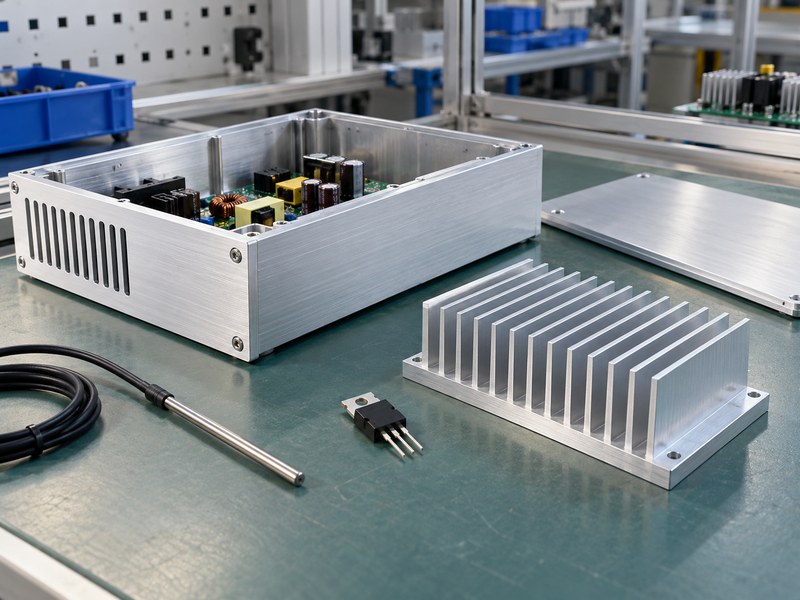
Use local inlet air temperature for a voltage regulator heat sink calculation, rather than room temperature when the product heats its own enclosure. Choose a junction target that respects the device’s operating limits and your design margin. Keep absolute maximum ratings separate from normal operating acceptance.
Account for nearby heat sources
A regulator beside a transformer or power stage may receive air warmer than the chamber setting. If you assume 40°C local air while the installed sink receives 55°C air, the temperature budget shrinks by 15°C. Sensor placement should capture the air entering the sink without touching a hot surface or sitting directly in a misleading exhaust stream.
- Record chamber and local inlet air temperatures separately.
- Include the installed cover and neighboring loads.
- Define the highest intended external operating temperature.
State the junction target
For an example calculation, a 110°C target and 45°C local ambient permit a 65°C junction rise. A different device or application may require a different target. Put the reason for that choice in the design record so later reviewers do not mistake an assumption for a universal limit.
| Temperature | Meaning in the model |
|---|---|
| TA | Air surrounding the cooling surface |
| TJ,target | Chosen junction acceptance target |
| TJ,target − TA | Available temperature rise |
The temperature difference determines how much resistance the assembly can tolerate.
4. How do you select the correct package thermal value?
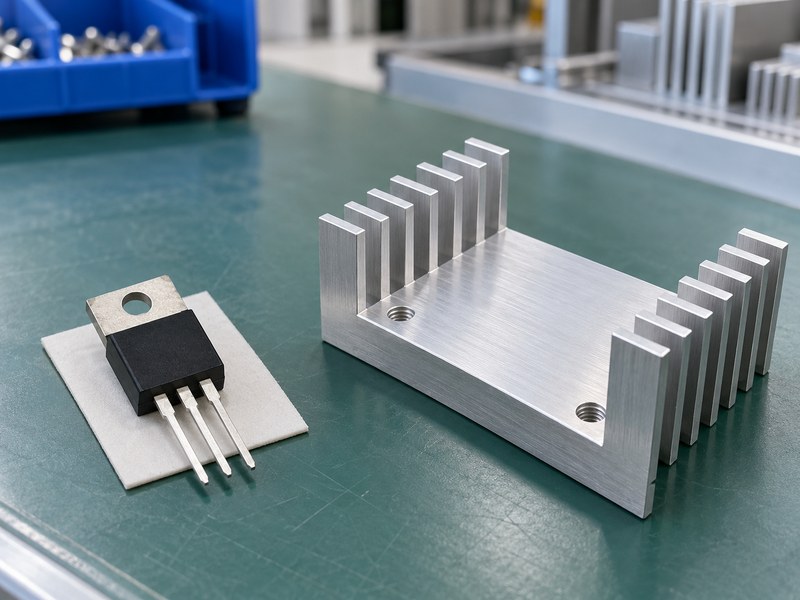
A voltage regulator heat sink calculation needs a package value tied to the surface that transfers heat into your assembly. Junction-to-case top, junction-to-case bottom and junction-to-ambient values describe different paths or test conditions. Package appearance alone does not identify the right number.
Read the metric definition
An exposed metal tab may support a case-to-sink path, while a soldered exposed pad usually transfers heat into board copper. Datasheets can also list characterization parameters such as ψJT for estimating junction temperature from a measured top temperature under stated conditions. Do not treat those parameters as interchangeable series resistances.
- Match the exact device and package option.
- Identify which surface the datasheet defines as case.
- Read notes describing the test board or cooling boundary.
Avoid double counting
RθJA describes the complete junction-to-ambient behavior for its test arrangement. Adding it to RθJC and a sink rating counts overlapping paths. If your board and sink provide substantial parallel cooling, a more detailed model or measured system result may be needed to resolve their contributions.
| Metric | Screening caution |
|---|---|
| RθJC | Use the correct case surface |
| RθJA | Do not append it to a series sink model |
| ψJT | Follow its measurement-estimation purpose |
Resolve the thermal path before comparing numeric values.
5. How much resistance does the interface add?
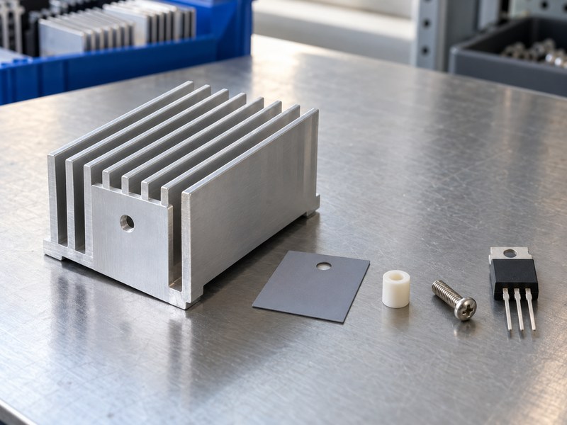
The interface contribution in a voltage regulator heat sink calculation depends on material, contact area, assembled thickness and pressure. A convenient default can be useful during a concept review, but the released calculation needs data suitable for the real mounting stack.
Convert supplier data carefully
Some suppliers report thermal impedance per unit area, while others report resistance for a particular test area and force. Keep the units explicit when applying those results to a smaller regulator tab. Bulk thermal conductivity and thickness alone may omit contact resistance at both surfaces, especially when the joint is uneven or lightly clamped.
- Record the tested contact area and pressure.
- Include electrical insulation requirements before comparing pads.
- Check whether phase-change or grease materials need process controls.
Check the assembled thickness
A thicker insulating pad may accommodate a mechanical gap but increase the junction-to-sink temperature drop. Screws and clips also affect compression and repeatability. Use the approved assembled stack in both thermal and electrical acceptance tests so the calculation refers to the configuration you actually build.
| Interface input | Evidence to retain |
|---|---|
| Material | Supplier and grade |
| Thickness | Assembled or specified condition |
| Resistance | Area, force and test method |
The interface belongs in the thermal budget before sink selection begins.
6. How do you work through a complete example?
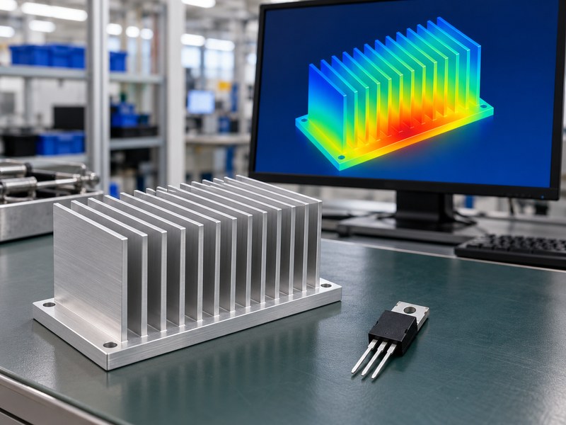
A complete voltage regulator heat sink calculation subtracts package and interface drops from the permitted rise. Suppose PD is 2.5 W, TA is 45°C, TJ,target is 110°C, applicable RθJC is 4°C/W and RθCS is 1°C/W. The maximum sink resistance is 21°C/W.
Calculate each step
The available rise is 110 − 45 = 65°C, so the complete junction-to-air budget is 65/2.5 = 26°C/W. Subtracting 4°C/W for the package and 1°C/W for the interface leaves 21°C/W for the sink. All five values are explicit example assumptions, rather than a recommendation for a specific regulator or finished product.
- Available rise: 65°C.
- Package and interface rise: 2.5 × 5 = 12.5°C.
- Remaining sink-to-air rise: 52.5°C.
Check the answer in reverse
If a candidate provides 18°C/W under matching conditions, the model predicts TJ = 45 + 2.5 × (4 + 1 + 18) = 102.5°C. That is 7.5°C below the example target. Review uncertainty before treating that remaining margin as adequate for production.
| Example quantity | Result |
|---|---|
| Total allowed resistance | 26°C/W |
| Maximum sink resistance | 21°C/W |
| Predicted TJ with an 18°C/W sink | 102.5°C |
The reverse calculation checks arithmetic and makes the remaining margin visible.
7. How should you check tolerances and uncertainty?
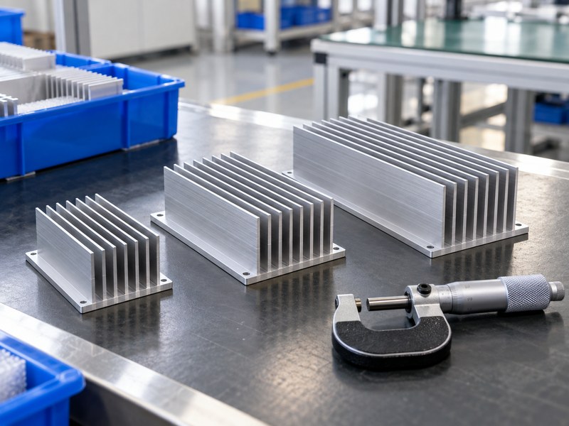
Check uncertainty by repeating the voltage regulator heat sink calculation with credible variations in loss, air temperature and interface performance. A result that passes only with optimistic inputs needs another review. Avoid hiding uncertain inputs behind a single precisely formatted temperature.
Change one input at a time
In the preceding example, increasing local air temperature from 45°C to 55°C raises predicted junction temperature from 102.5°C to 112.5°C. Keeping 45°C air but increasing power from 2.5 W to 3 W gives 114°C with the same 23°C/W total resistance. Either change would exceed the illustrative 110°C target.
- Test the high-input operating point.
- Review local air-temperature uncertainty.
- Include interface and assembly variation.
Use evidence for combined corners
One-at-a-time checks show sensitivity, while a release review needs the combinations that can occur in service. If several adverse conditions can coincide, calculate that combined case. If they cannot coincide, retain the operating evidence that supports excluding the combination.
| Changed example input | Predicted junction temperature |
|---|---|
| Baseline: 45°C, 2.5 W | 102.5°C |
| Air increased to 55°C | 112.5°C |
| Loss increased to 3 W | 114°C |
Sensitivity checks identify which assumptions deserve tighter control or more cooling margin.
8. Can you apply the formula to a switching regulator?
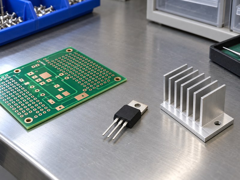
The same temperature-rise framework can support a voltage regulator heat sink calculation for a switching design, but its device loss must come from the correct electrical model. Applying (VIN − VOUT) × IOUT to an entire buck converter would misrepresent normal switching operation.
Separate converter loss from package loss
Efficiency can estimate total converter loss at a defined operating point, but that loss is distributed across switches, inductor, controller and other parts. The heat source beneath one sink may represent only part of the total. Use component loss models, vendor tools or measurements that identify which losses enter the cooled package.
- Include conduction and switching behavior where applicable.
- Use efficiency at the relevant load and voltages.
- Avoid assigning inductor loss to a regulator IC’s junction.
Revisit the physical path
A switching power stage may transfer heat mainly through a PCB pad, copper planes or multiple devices beneath one spreader. Its mounting arrangement may require a board-aware thermal model. Keep each junction’s local path and the shared air-side or chassis path distinct.
| Electrical design | Suitable loss input |
|---|---|
| Linear regulator | Pass-element and ground-current loss |
| Buck converter assembly | Distributed converter losses |
| Individual power stage | Loss in that cooled package |
The thermal equation is useful only when its heat input belongs to the modeled source.
9. How do you turn the result into a supplier specification?
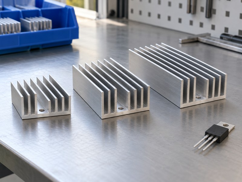
Turn a voltage regulator heat sink calculation into a supplier specification by stating maximum RθSA together with heat load, orientation and airflow. A resistance target without conditions invites incomparable quotations. Include the package contact drawing and available mechanical envelope.
Ask for comparable thermal data
When reviewing extruded heat sinks, ask how the quoted resistance was measured or modeled and where temperature was taken. A rating at one heat input or forced-air condition may not transfer directly to another. Identify what the supplier will validate on the sample before selecting a production profile.
- State the target and its operating conditions.
- Include interface and mounting assumptions.
- Request the proposed test arrangement with the quotation.
Keep mechanical requirements alongside the target
Base flatness, hole location, finish and permitted mass influence whether the calculated path can be built. A custom mounting face may suit CNC machined heat sinks, while a catalog profile may meet the same thermal requirement at lower development effort. Compare the completed assembly and its acceptance evidence.
| Specification line | Information to include |
|---|---|
| Performance | Maximum resistance and conditions |
| Interface | Contact area and mounting stack |
| Packaging | Envelope, holes and orientation |
The supplier needs both the thermal target and the constraints around it.
10. How do you validate the calculation before release?
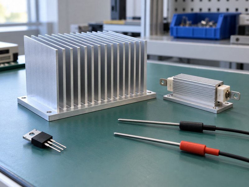
Validate a voltage regulator heat sink calculation by testing the assembled prototype at its documented operating corners. Compare measured temperatures with the model and investigate any unexplained difference. Keep the test configuration, sensor method and drawing revisions with the calculation.
Close the gap between model and hardware
Check actual electrical loss, local air temperature and interface assembly before changing assumed thermal resistance to force a fit. Measurements on reflective metal need suitable emissivity treatment or a contact method. A model adjusted to one operating point should still explain other measured loads within its stated limits.
- Test with the final cover, orientation and cooling hardware.
- Wait for an appropriate steady condition at sustained load.
- Record repeatability across more than one assembly when needed.
Send a reviewable design brief
Bring your calculation, package drawing and prototype observations when you contact us. We can review the heat sink geometry and mounting requirements against those inputs. Agree on the acceptance test before releasing the part for repeat orders.
| Release evidence | Required relationship |
|---|---|
| Calculation | Matches the intended operating range |
| Prototype | Uses the specified assembly |
| Production drawing | Reproduces the validated thermal path |
Release the calculation and tested assembly as one controlled configuration.
Q1: Can I use a typical RθJC value for every regulator?
No. Match the exact package, contact surface and datasheet definition. Similar package outlines can have different internal thermal paths.
Q2: What’s the best way to handle an unknown interface value?
Request suitable supplier data or measure the assembled joint. A clearly labeled estimate can support screening, but it should not become an unexplained release assumption.
Q3: How do I know if a calculator result is unrealistic?
Check units, heat loss and metric definitions. A negative sink allowance calls for a design change or a better model, rather than a physically impossible sink.
Q4: Can I use average power for a pulsed load?
Sometimes. Pulse duration and repetition affect junction-temperature peaks. Use transient thermal information or suitable measurements when a steady-state average hides those peaks.
Q5: Can a larger base fix an overheating regulator?
It may improve spreading, but it cannot remove package or interface limits. Identify the dominant temperature drop before changing base thickness.