
Voltage regulators can share a heat sink when their exposed electrical connections are compatible or properly insulated, and the sink can reject their combined heat. Check every junction separately. Two devices on one extrusion reduce part count, but they also share temperature rise, mounting space and possible conductive paths.
1. Can voltage regulators share a heat sink safely?
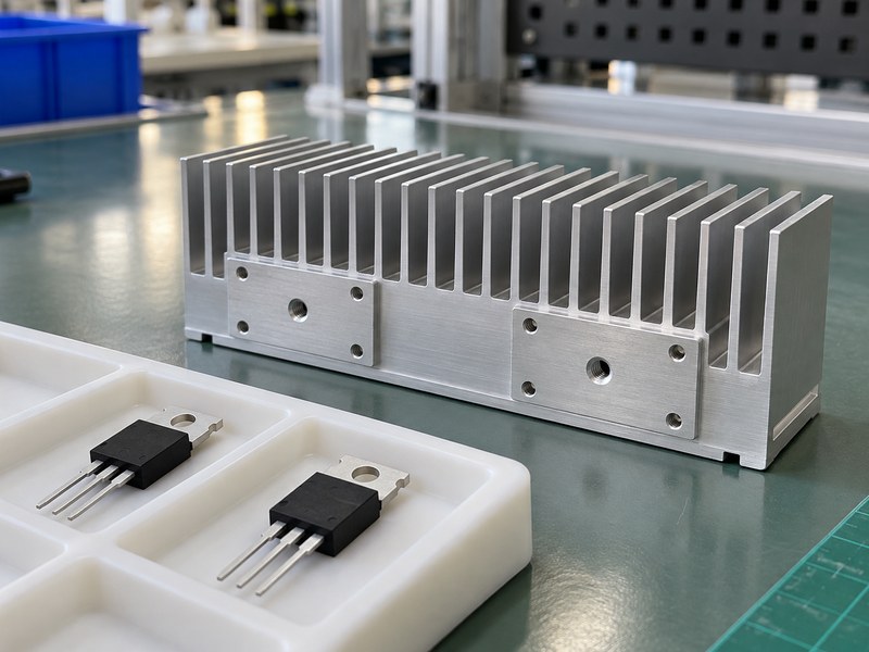
The answer to “can voltage regulators share a heat sink” is yes when the electrical and thermal design supports the shared assembly. Package tabs may connect with different circuit nodes, so direct metal contact needs review. A common base also carries heat from all attached devices into the same air path.
Identify what the metal connects
Start with the exact part numbers, package drawings and tab connections. Two regulators from one package family can have different electrical functions, and a positive regulator need not match a negative or adjustable device. Include the sink’s connection with the chassis, brackets and any accessible metal in the electrical review.
- List each exposed tab or pad potential.
- Check fasteners and clips as conductive parts.
- Identify the intended chassis bonding arrangement.
Define the shared cooling requirement
A board-level heat sink that handles one device may be inadequate after adding another. Record the credible simultaneous losses and local air temperature. The first review should establish electrical compatibility and a thermal budget before assigning a mounting position to either device.
| Shared assembly check | Required information |
|---|---|
| Electrical | Tab potentials and chassis connection |
| Thermal | Simultaneous loss in every device |
| Mechanical | Contact areas and fastening access |
Approve those conditions together before committing to a common profile.
2. When can the tabs contact the same metal directly?
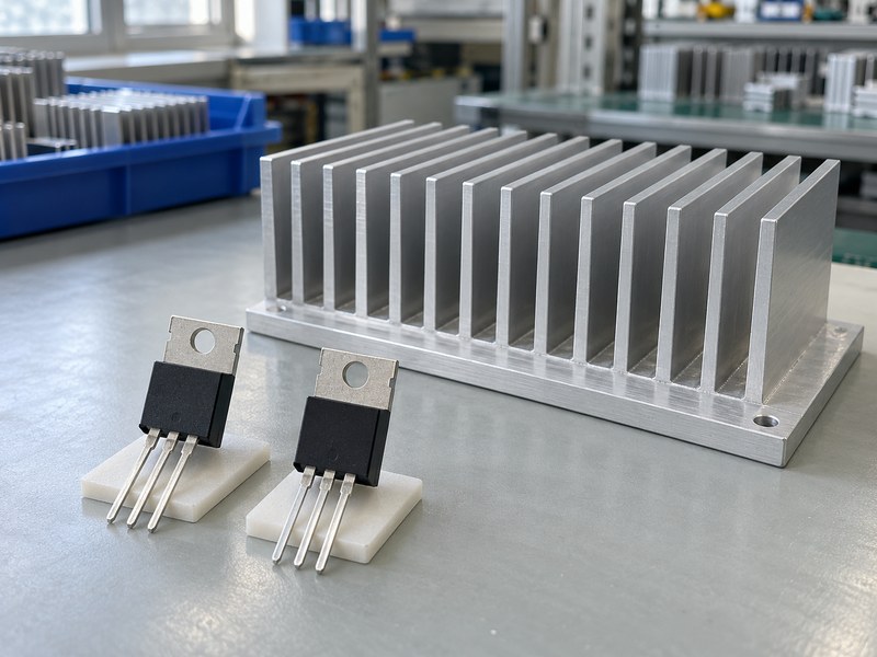
Direct tab contact may be possible when the exposed nodes are intended to share the same potential, which partly answers “can voltage regulators share a heat sink.” That decision still depends on the exact circuit and product requirements. Similar-looking packages do not establish electrical compatibility.
Check the part and circuit revision
Read the manufacturer’s pin-function and package notes for the selected device; package drawings in that datasheet are one example of the information to check. Then check the schematic connections and permitted chassis relationship. If a later substitute changes the tab connection, a mechanically interchangeable part could alter the electrical assembly, so include tab potential in the component substitution review.
- Verify each ordering code rather than a family nickname.
- Compare schematic node names and operating potentials.
- Review fault and service conditions relevant to the product.
Keep the bonding arrangement deliberate
Do not assume that a floating sink stays floating after installation. A screw through a bracket, enclosure coating damage or service replacement can connect it with another conductor. State whether the sink is bonded, insulated or inaccessible and make the assembly match that decision.
| Tab arrangement | Next check |
|---|---|
| Same intended node | Confirm chassis compatibility |
| Different nodes | Design the insulation stack |
| Uncertain substitute | Obtain the exact package information |
Treat the sink as a conductor whenever you review its mounting routes.
3. How should you insulate incompatible package tabs?
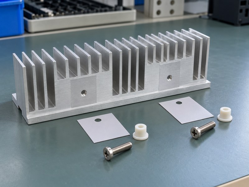
Incompatible tabs need a specified isolation system before “can voltage regulators share a heat sink” becomes an acceptable assembly decision. The pad beneath a tab is only part of that system. Screws, shoulders, clips and adjacent metal can bridge the insulated contact area.
Specify a complete mounting stack
Select pad material, thickness, hole geometry and fastener insulation for the device and product requirements. An insulating shoulder washer must separate the screw from the tab where that route would otherwise conduct. Align the parts without folds, burrs or exposed edges that compromise the intended separation.
- Check the pad’s coverage around the contact face.
- Specify the correct shoulder and hole dimensions.
- Keep adjacent leads clear of the common metal.
Include assembly variation
Review the insulation after tightening and after the relevant environmental tests. A pad that tears during installation or creeps away from a sharp edge may not retain its function. Use heat sink mounting hardware that maintains the intended force without damaging the package or insulation.
| Stack component | Acceptance point |
|---|---|
| Interface pad | Correct grade, coverage and thickness |
| Fastener insulation | No unintended tab-to-screw route |
| Finished assembly | Defined electrical acceptance test |
Test the same stack that will appear on the production drawing.
4. How do you add the regulators’ heat losses?
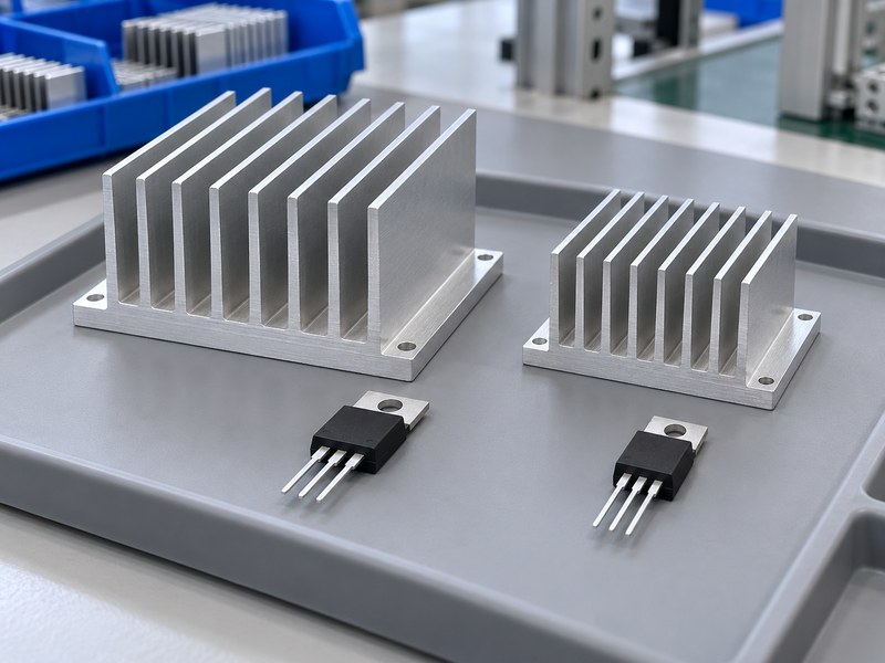
Add the simultaneous device losses when evaluating “can voltage regulators share a heat sink” thermally. For linear regulators, calculate each loss from its voltage drop, output current and applicable ground-current term. For switching devices, use the loss in each cooled package, rather than assigning the whole converter’s loss to one junction.
Build an operating-state table
Consider two illustrative linear regulators dissipating 4 W and 6 W during a sustained operating state. Their common sink must reject approximately 10 W, plus any other heat sources that use the same base. If loads vary with operating mode, list the modes instead of combining arbitrary maximum values that cannot occur together.
- Calculate device losses separately.
- Identify credible simultaneous load combinations.
- Include other power devices mounted on the profile.
Review startup and abnormal states
Short periods of high loss can produce junction peaks that a steady-state total misses. Check pulse duration and repetition with suitable transient information or testing. Also review modes where one regulator remains heavily loaded after another shuts down, because the shared base may still be warm from earlier operation.
| Example mode | Device A | Device B | Combined loss |
|---|---|---|---|
| Sustained full load | 4 W | 6 W | 10 W |
| A operating alone | 4 W | 0 W | 4 W |
| B operating alone | 0 W | 6 W | 6 W |
The mode table gives the shared cooling surface a traceable heat input.
5. How do you estimate each junction temperature?
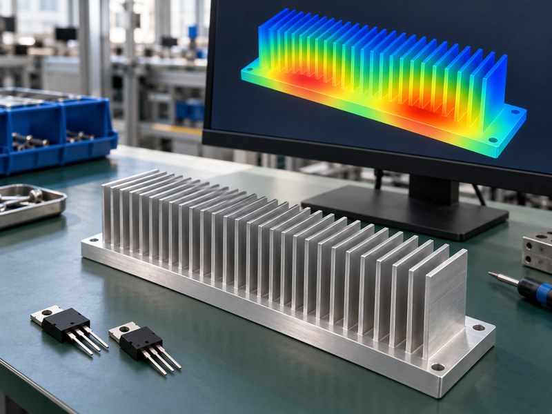
Estimate every junction separately when deciding “can voltage regulators share a heat sink.” For a simplified nearly uniform base, TJ,i ≈ TA + Ptotal × RθSA + Pi × (RθJC,i + RθCS,i). This separates the shared sink rise from each device’s own package and interface drop.
Work through a shared-base example
Assume 40°C local air, 10 W total loss and a sink resistance of 3°C/W under the intended conditions. The simplified base temperature is 70°C. A 4 W device with a combined package and interface resistance of 5°C/W reaches about 90°C, while a 6 W device with a 4°C/W local path reaches about 94°C.
- Compare each estimate with that device’s chosen target.
- Keep the package and interface values device-specific.
- Label all assumed values before prototype review.
Check the uniform-base assumption
A compact source on a thin or long base can create a local hot region. The common-base equation omits that spreading effect and may underestimate a junction near concentrated loading. Use a spatial model or measurements when the remaining temperature margin depends on a small difference between local base temperatures.
| Illustrative quantity | Result |
|---|---|
| Common base rise | 30°C |
| Device A junction estimate | 90°C |
| Device B junction estimate | 94°C |
The device with more heat is not automatically the device with the highest junction temperature.
6. How does spacing affect thermal coupling?
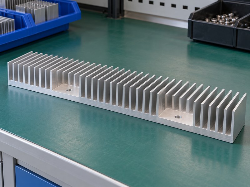
Spacing affects local base temperatures and thermal coupling, so it influences “can voltage regulators share a heat sink” beyond the combined wattage. Two closely grouped sources can produce a hotter mounting region than well-separated sources on the same profile. The benefit depends on base thickness, material and available cooling surface.
Balance spreading and mechanical access
Place devices where the base can spread heat into usable fins while preserving clearances and fastening access. Moving a device farther away may improve distribution but require longer leads, a changed board layout or a different bracket. Review those changes together rather than optimizing heat flow independently of assembly.
- Keep contact faces fully supported by the base.
- Allow room for tools, insulating washers and tolerances.
- Check the hottest device’s local mounting region.
Test both load directions
Operate device A alone and observe temperatures near device B, then reverse the loads. Those checks help reveal how strongly the mounting regions interact. Repeat the intended combined load because convection and material behavior may prevent a simple sum of isolated temperature rises from predicting every condition accurately.
| Placement question | Evidence needed |
|---|---|
| Sources too close? | Local base-temperature measurements |
| Base too thin? | Spreading analysis or prototype comparison |
| Sources separated? | Lead, access and clearance review |
Choose positions using the coupled assembly, rather than isolated device ratings.
7. What airflow conditions should you use?
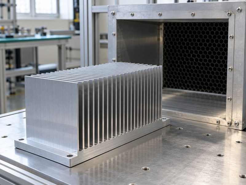
Use the shared profile’s installed airflow when deciding “can voltage regulators share a heat sink.” Both devices depend on the same air-side path, and one upstream heat source can warm the air reaching another region. A fan rating alone does not establish flow through the fins.
Follow the whole air route
Check inlet restrictions, filters, bypass gaps and outlet paths with the enclosure assembled. A long extruded heat sink may see uneven cooling along its length. Ask for thermal data that matches orientation and flow conditions, or measure the proposed assembly before accepting a nominal resistance figure.
- Measure local inlet temperatures near the cooling surface.
- Keep fin passages aligned with the intended air path.
- Review cooling degradation required by the application.
Keep passive cooling orientation fixed
For natural convection, nearby walls and board orientation affect how warmed air escapes. A profile tested vertically may perform differently after rotating into a compact enclosure. Preserve the intended installation orientation in tests and include both regulators’ sustained heat load.
| Cooling mode | Shared-assembly check |
|---|---|
| Natural convection | Orientation and free air path |
| Forced air | Flow through each heated region |
| Enclosure conduction | Combined heat into the wall |
The entire assembly must retain an available path for its combined heat.
8. Which mechanical changes can undermine the design?
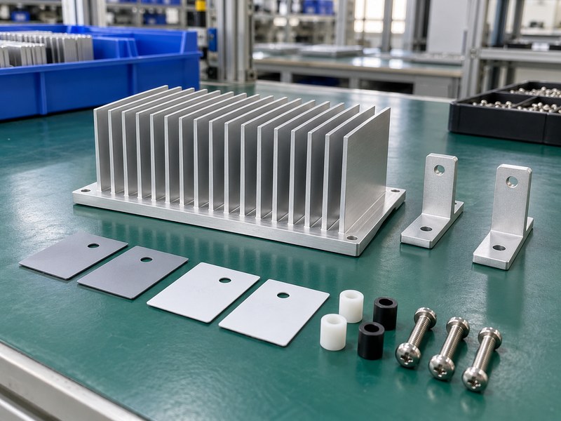
Mechanical changes can reverse a previous “can voltage regulators share a heat sink” decision by changing contact, insulation or structural loading. Moving a hole, substituting a pad or tightening one fastener differently can affect the tested thermal path. Keep both device locations on the controlled assembly drawing.
Avoid using leads as supports
A shared profile may weigh more than a small individual sink. Support it through suitable brackets or board mounting features so vibration and handling do not load the regulator leads excessively. Account for relative expansion between the board, packages and profile when reviewing the joint and its assembly sequence.
- Define support points and fastening order.
- Check access for both devices after board installation.
- Review connector, cover and component clearances.
Control the contact faces
When custom pockets or mounting lands are required, CNC machined heat sinks can provide the relevant geometry. Specify contact flatness, hole position and allowed surface finish. The assembler should be able to verify that both tabs seat properly without forcing the packages into position.
| Change | Review it for |
|---|---|
| Pad substitution | Resistance and electrical rating |
| Hole movement | Contact support and lead stress |
| Larger profile | Mass, access and board loading |
Mechanical approval should reproduce the same thermal and insulation stack as the prototype.
9. How do you test a shared heat sink prototype?
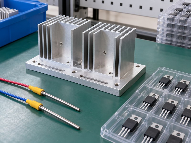
Test each device alone and both together to verify “can voltage regulators share a heat sink” for the intended product. Record electrical loss, local ambient, case temperatures and local base temperatures. Use the exact interface and insulation arrangement planned for production.
Separate local and shared temperature drops
Measure near each mounting area with a method appropriate for the package and surface. A large case-to-base drop points toward the local package or interface path, while a hot base under both devices points toward shared cooling capacity. Electrical acceptance should follow the product’s specified insulation and bonding tests after assembly.
- Record device A alone, device B alone and combined load.
- Test the final cover and installation orientation.
- Repeat relevant startup or changing-load sequences.
Retain the test configuration
Include pad grade, thickness, torque or clip force, part revisions and sensor positions in the report. If a substitute device or interface changes, use those records to decide what needs retesting. One successful unit cannot establish repeatability without suitable production controls.
| Test | What it checks |
|---|---|
| One device at a time | Local path and cross-heating |
| Combined sustained load | Shared cooling capacity |
| Electrical acceptance | Intended isolation and bonding |
The test matrix needs to cover both thermal interaction and conductive paths.
10. What should you send for an engineering review?
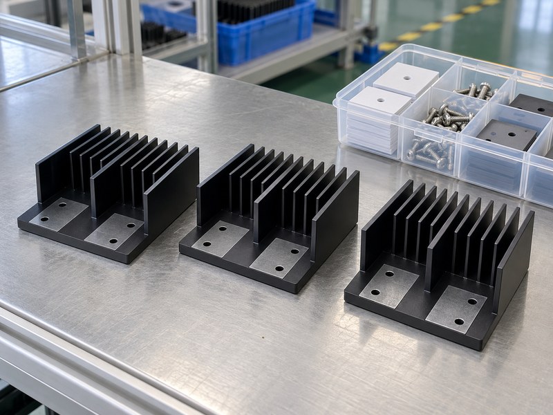
To settle “can voltage regulators share a heat sink,” send the device list, tab potentials, loss table and mechanical envelope together. Include insulation requirements and local cooling conditions. Those inputs make a common profile proposal reviewable against a specific electrical and thermal design.
Provide one assembly brief
Show contact footprints, hole patterns and the board relationship on the same drawing. List which operating states can occur simultaneously and identify any uncertain loss or interface values. If the chassis contributes cooling, include its geometry and contact arrangement rather than treating it as an unspecified temperature reference.
- Attach device and package information.
- Define each junction target and the local ambient range.
- Include the proposed prototype acceptance method.
Choose the shared design from test evidence
When you contact us, bring the combined-load record and mounting drawing so we can discuss a suitable common extrusion or machined base. Compare the proposal with separate sinks using the same acceptance conditions. Release the arrangement that meets the limits and can be assembled consistently.
| Review input | Design decision it supports |
|---|---|
| Tab and insulation record | Electrical mounting arrangement |
| Loss and temperature budget | Cooling capacity |
| Drawing and test method | Repeatable sample acceptance |
Keep the approved device list and mounting stack with the released profile drawing.
Q1: Can I share a sink between positive and negative regulators?
Possibly, with the correct isolation arrangement. Verify each exposed metal connection because directly joining incompatible tabs can connect different circuit nodes.
Q2: What’s the best way to check cross-heating?
Test each source alone and measure temperatures near the other mounting area. Then test the intended combined load and compare the result with your model.
Q3: How do I know if one insulating pad is enough?
Trace every conductive route. The screw, clip or bracket can bypass a tab pad, so the complete mounting stack needs review and electrical acceptance.
Q4: Can I use two individual sink ratings for one common profile?
No. The shared surface rejects combined heat under one set of cooling conditions. Each junction still needs its own package and interface calculation.
Q5: Can one regulator’s shutdown protect the other?
Do not rely on that behavior without a validated control design. Each device has its own thermal response, protection behavior and permitted operating limits.