
Attach a heat sink to a voltage regulator through the package’s intended thermal surface, using a controlled interface and an approved screw or clip arrangement. Check electrical isolation before tightening the joint. A sink that sits securely can still cool poorly if the contact face, pad thickness or mounting force is wrong.
1. How to attach heat sink to voltage regulator packages?
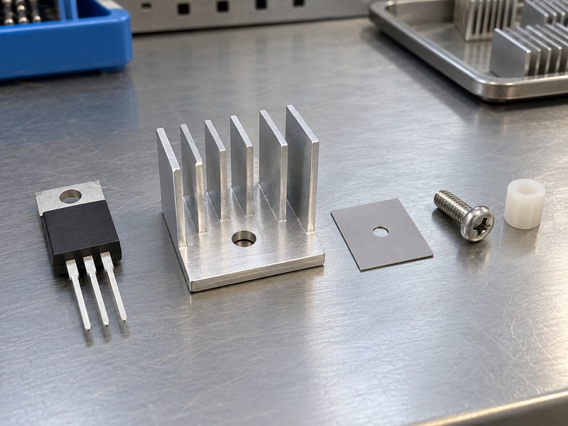
When planning how to attach heat sink to voltage regulator packages, start with the exact package drawing and mounting guidance. A tab-mounted through-hole device, an exposed-pad surface-mount device and a small molded regulator need different cooling arrangements. Identify the intended heat-transfer surface before choosing hardware.
Match the mounting method with the package
A package with a metal tab and mounting hole may accept a screw or suitable clip, while a surface-mounted thermal pad normally connects through solder into board copper. An adhesive sink on the molded top follows a different thermal path and may provide limited benefit. Review board-level heat sinks around the device, rather than selecting a shape and forcing the package to fit.
- Confirm the complete ordering code and package option.
- Locate the defined contact surface and permitted force.
- Check access before installing nearby components.
Prepare the assembly information
Keep a drawing or approved assembly instruction at the workstation. It should identify the sink revision, interface, insulation pieces and fastening method. If several similar regulators use different tab connections, make those differences visible in the bill of materials and inspection record.
| Package feature | Mounting question |
|---|---|
| Exposed tab | Screw, clip and insulation arrangement? |
| Soldered thermal pad | Board copper and attachment process? |
| Molded top | Is this a useful rated thermal path? |
Choose the attachment around the package’s real construction.
2. How should you inspect the contact surfaces?
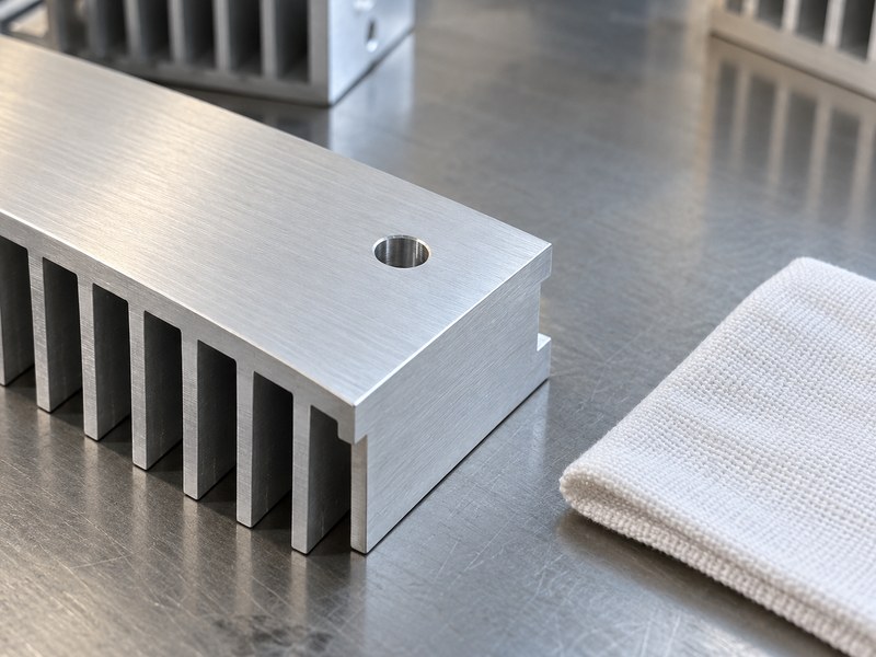
Contact inspection is part of how to attach heat sink to voltage regulator assemblies consistently. The mating faces need the specified flatness, surface condition and available area. A raised burr near the mounting hole can hold a tab away from the base even after the screw feels tight.
Check before applying interface material
Inspect the mounting land, hole edge and device tab for damage or contamination. Use the cleaning process approved for the materials and package, then allow surfaces to dry as required. Do not improvise sanding or aggressive solvents on a finished component because the resulting damage or dimensional change may be difficult to inspect.
- Look for burrs, dents and raised coating edges.
- Confirm the tab sits within the supported contact area.
- Keep debris outside the mating surfaces and lead area.
Inspect the finished part
Specify dimensions after machining and coating when the finish changes the contact or hole fit. A surface that was flat before anodizing may still need a controlled finished-state requirement. For CNC machined heat sinks, identify the contact land and its datums rather than applying an unexplained tolerance to the whole part.
| Surface feature | Acceptance evidence |
|---|---|
| Contact land | Specified flatness and condition |
| Hole edge | No burr affecting seating |
| Finished surface | Matches the released drawing |
Inspect the joint before interface material hides its contact faces.
3. How much thermal interface material should you use?
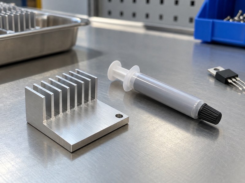
Use the specified interface material and application process when deciding how to attach heat sink to voltage regulator surfaces. Grease fills microscopic surface gaps; it should not be expected to bridge an uncontrolled mechanical gap. Pads and phase-change materials need their own thickness, pressure and handling requirements.
Follow the material’s application guidance
Too much grease can spread outside the intended contact area, while too little coverage can leave poorly contacted regions. Follow the supplier’s guidance for the selected material and geometry rather than using a universal layer thickness. If the material is electrically conductive, review where displaced material could contact leads or other circuitry.
- Specify material grade and application quantity or method.
- Check storage life and handling conditions.
- Keep release liners out of the completed joint.
Include the interface in the thermal budget
The assembled interface resistance depends on area, material and pressure. Substituting a thicker pad may solve a mechanical gap but raise junction temperature. Recalculate the thermal path and confirm the result on the complete prototype before approving a material change.
| Interface type | Process variable |
|---|---|
| Grease | Coverage and controlled application |
| Solid pad | Thickness, compression and liner removal |
| Phase-change material | Supplier-defined assembly conditions |
Use the interface as a controlled part of the joint, rather than a general-purpose filler.
4. How do you install electrical insulation correctly?
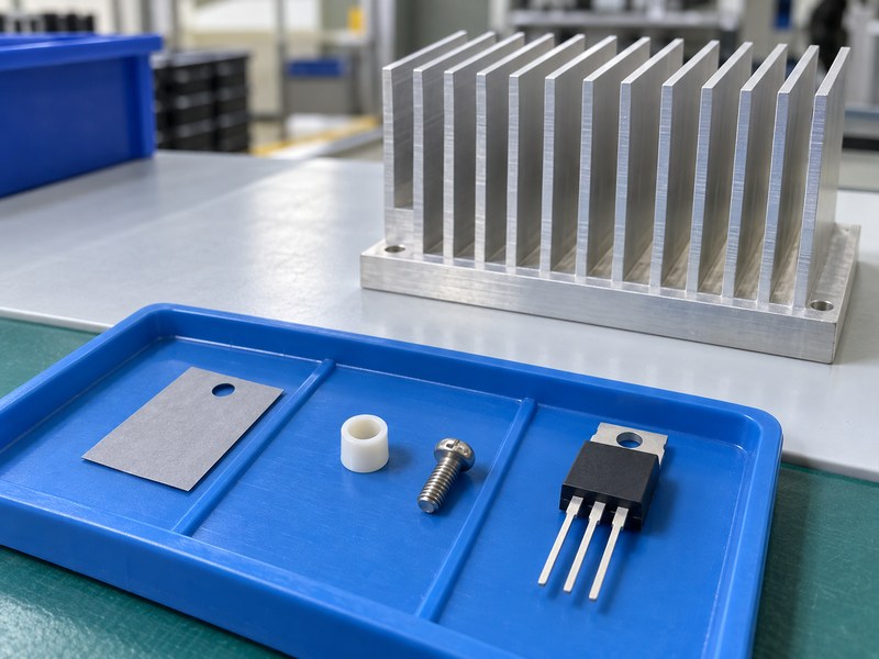
Electrical insulation changes how to attach heat sink to voltage regulator tabs when exposed metal carries an incompatible potential. Verify the selected part’s tab connection before assembling it. A tab pad may need a shoulder washer or other fastener insulation to block conductive paths around the pad.
Trace the fastener route
Place the pad and shoulder components in the order specified by the approved mounting system. Check that the shoulder fits the tab hole and isolates the screw where required. A screw touching the tab can defeat the intended separation even when the pad beneath the tab appears correctly positioned.
- Align pad holes without tearing or folding the material.
- Keep burrs and sharp edges away from insulation.
- Inspect the screw, clip and bracket routes.
Verify after tightening
Insulation must remain correctly positioned in the assembled joint. Compression, rotation and handling can shift a pad or damage its edge. Perform the product’s defined electrical acceptance checks with the final screw, pad, washer and sink arrangement; do not treat black anodizing as a substitute for a specified insulation system.
| Possible bypass | Inspection point |
|---|---|
| Screw shank to tab | Shoulder insulation |
| Tab edge to base | Pad coverage and alignment |
| Clip to live metal | Approved clip arrangement |
Approve insulation after assembly, when its actual conductive routes are present.
5. How should you tighten screws or fit spring clips?
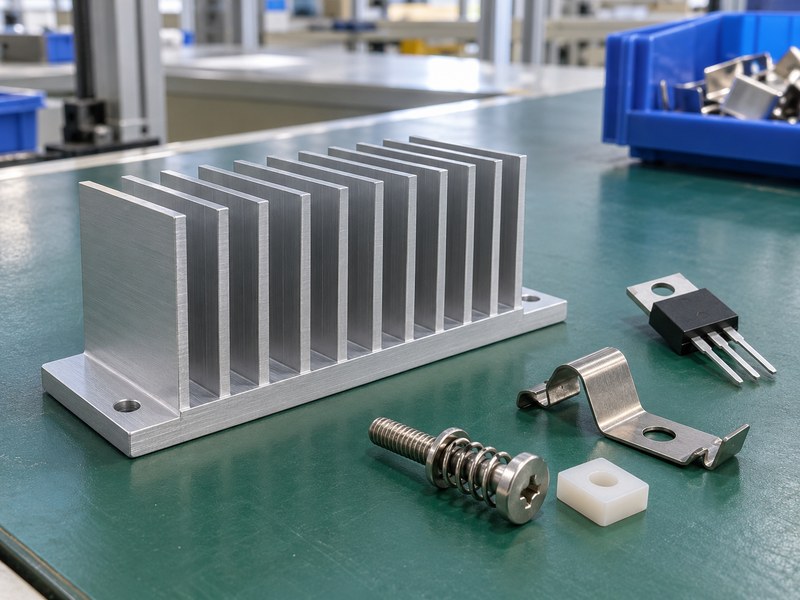
Use the package and hardware suppliers’ approved force limits when planning how to attach heat sink to voltage regulator tabs. There is no universal torque for every TO-220 assembly. Screw size alone does not account for tab strength, thread engagement, washer friction or interface compression.
Control the joint force
Use a suitable controlled tool for the released fastening process and support the assembly while tightening. Avoid pulling a misaligned tab into place with the screw. Extra force can bow the tab or damage insulation, while inadequate force can leave unstable contact during vibration or thermal cycling.
- Specify torque or clip force with its approved hardware.
- Define tightening order for multi-device assemblies.
- Check thread engagement and screw length.
Select serviceable hardware
If a unit will be opened for maintenance, define whether pads and fastening elements can be reused. A repeatable heat sink mounting hardware arrangement should let an assembler achieve the required contact without relying on feel. Record any retention method required by the product’s environment.
| Fastening detail | Reason to specify it |
|---|---|
| Screw or clip type | Controls the load path |
| Force limit | Protects package and interface |
| Length and engagement | Prevents bottoming or loose joints |
Use a fastening specification that reproduces the tested contact condition.
6. How do you protect leads and PCB joints?
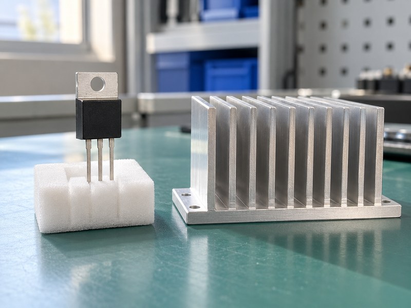
Protecting leads is part of how to attach heat sink to voltage regulator assemblies without adding mechanical failures. The heat sink should have suitable support, and the package should align without forcing its leads. A thermal joint must not turn electrical pins into structural mounting members.
Check the assembly sequence
Review whether the approved process mounts the device before soldering, uses a locating fixture or provides another way to control alignment. Package suppliers may specify lead-forming distances and bending limits. Follow those requirements instead of bending leads at the body to compensate for a misplaced sink hole.
- Support the sink during assembly and handling.
- Keep leads clear of conductive edges.
- Check board strain near the package and supports.
Allow for installed loading
A larger sink adds mass and can load the board during shipping or vibration. Brackets, board standoffs and enclosure supports may be needed, depending on the product. Check clearance with connectors and the cover at the finished assembly’s tolerance limits, rather than only on a nominal CAD view.
| Mechanical issue | Review action |
|---|---|
| Hole misalignment | Correct the drawing or fixture |
| Heavy unsupported sink | Add suitable structural support |
| Lead near metal edge | Revise clearance and lead geometry |
Thermal contact should remain stable without stressing electrical connections.
7. How should you orient the heat sink after mounting?
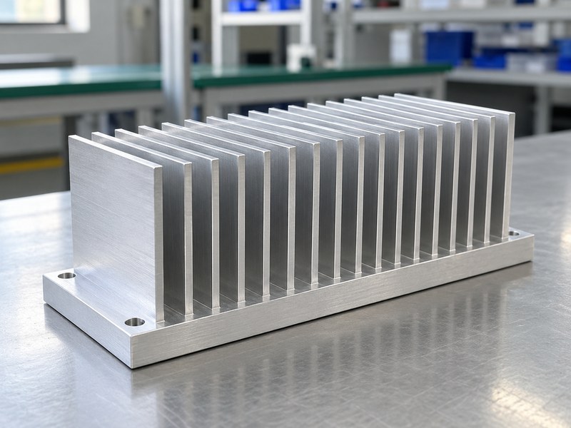
Orientation matters after working out how to attach heat sink to voltage regulator packages. The mounted sink still needs a usable path into air or the chassis. A mechanically neat installation can trap warm air against a cover or position fin channels across the intended flow.
Keep the air-side surface usable
For natural convection, review how warmed air can leave the fin passages in the installed orientation. For forced air, review actual flow through the channels, including filters and bypass gaps. Compare extruded heat sinks using data appropriate for those conditions.
- Check spacing around inlets and outlets.
- Keep cable bundles out of the fin passages.
- Measure local inlet air after nearby heat sources.
Review chassis-mounted designs separately
If the sink transfers heat into an enclosure, specify that contact joint and the enclosure’s available cooling surface. Air trapped inside a closed box does not provide the same boundary as open room air. Test with the real wall contact, cover and mounting orientation before releasing the design.
| Cooling arrangement | Installation check |
|---|---|
| Passive fins | Warm-air escape path |
| Fan-cooled fins | Actual channel flow |
| Chassis contact | Defined joint and external heat rejection |
Mount the sink where its validated cooling conditions can exist.
8. How do you check the finished assembly thermally?
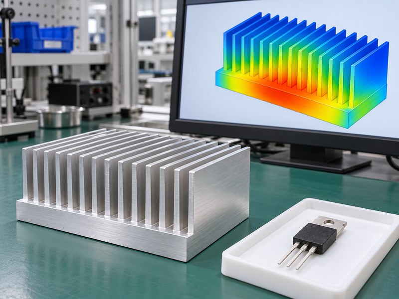
A thermal check confirms whether the chosen method for how to attach heat sink to voltage regulator packages meets the design target. Test the complete assembly at defined loss and local air temperature. Measure at locations that match the package’s thermal information and your model.
Record a useful temperature comparison
Compare package and nearby sink-base temperatures with suitable sensors and attachment methods. A large temperature drop across the mounting path may indicate interface or contact problems, although the package path also contributes. Infrared readings on reflective metal need attention to emissivity and reflections before you draw conclusions from the apparent temperature.
- Record electrical loss and local air temperature together.
- Test at sustained load until an appropriate steady state.
- Include the final cover, orientation and airflow hardware.
Investigate before enlarging the sink
If the package remains hot while the base is relatively cool, inspect the mounting path and thermal metric before adding fin area. If both are hot, review loss and sink-to-air cooling. Keep the test observations with the exact pad, hardware and assembly revision so changes can be traced.
| Observation | Useful next check |
|---|---|
| Hot case, cooler base | Contact and interface path |
| Hot case and base | Total loss and air-side capacity |
| Variable repeats | Assembly force and interface coverage |
Use the temperature distribution to choose the next inspection step.
9. What should production inspectors verify?
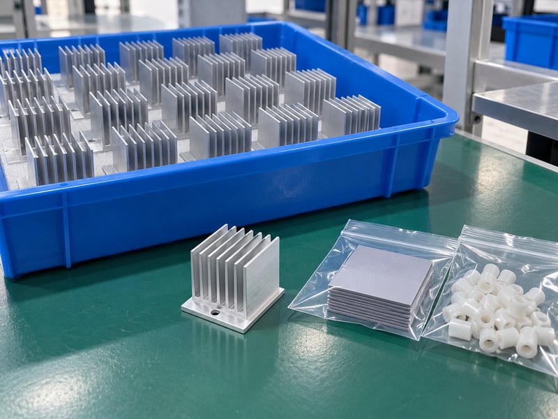
Production inspection should verify the controlled details of how to attach heat sink to voltage regulator assemblies, rather than checking only whether a screw is present. Part identity, interface placement, insulation and fastening evidence all affect whether production matches the validated prototype.
Use inspectable acceptance points
Choose checks that can reveal an assembly error before the product leaves the workstation. Examples include liner removal, pad alignment, screw length and recorded torque where the process requires it. Inspect leads and nearby components after tightening because a tool or shifting sink can introduce damage during the operation.
- Confirm pad and washer identity against the bill of materials.
- Inspect contact alignment and hardware seating.
- Complete the defined electrical acceptance checks.
Control substitutions and rework
A substitute interface or clip can change thermal and electrical behavior without altering the external appearance. Define approved equivalents and rework instructions before production needs them. Retest a changed configuration when the existing evidence does not cover its materials, force or geometry.
| Inspection stage | Example check |
|---|---|
| Before mounting | Correct parts and clean faces |
| After tightening | Seating, insulation and lead clearance |
| Final acceptance | Required electrical and functional tests |
Inspect the details that determine whether the joint matches the approved design.
10. What should the released mounting instruction contain?
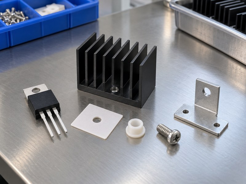
A released instruction for how to attach heat sink to voltage regulator packages should specify parts, sequence, force limits and acceptance checks. Include clear orientation information and revision control. Assemblers should not need to infer electrical isolation or interface placement from a general product photograph.
Tie the instruction to the drawing
Identify package, sink, pad and hardware revisions together. Define any fixture, cleaning or material application step that affects contact. Include the approved service and rework method where relevant, with replacement rules for insulation or interface materials that cannot be reused reliably.
- List part numbers and orientation references.
- Specify the controlled fastening process.
- Identify thermal and electrical acceptance records.
Prepare an engineering review
Send your package drawing, heat loss, interface choice and assembly envelope when you contact us. We can review a suitable sink and mounting arrangement with those constraints in view. Agree on prototype acceptance before approving the configuration for repeat production.
| Release document | What it controls |
|---|---|
| Assembly drawing | Geometry and parts |
| Work instruction | Sequence and force |
| Acceptance record | Required finished behavior |
Release the tested mounting stack with instructions that production can reproduce.
Q1: Can I attach a heat sink with ordinary adhesive?
Use an adhesive only if its thermal, mechanical and electrical properties suit the application and package. An unqualified glue layer can add resistance or fail during service.
Q2: What’s the best torque for a TO-220 screw?
Use the approved package and hardware limits. A universal torque based only on screw size ignores the tab, interface and thread conditions.
Q3: How do I know if a pad needs a shoulder washer?
Trace the screw’s conductive route. If it can connect the tab with the sink, use the specified fastener insulation and verify the completed stack.
Q4: Can I solder the regulator before fitting the sink?
Follow the approved assembly sequence. The finished joint should align without forcing leads or stressing solder connections; a fixture may be needed.
Q5: Can I reuse an interface pad after removing the sink?
Only if the selected material and approved process allow reuse. Replace damaged, contaminated or permanently deformed material and repeat required acceptance checks.