
A linear voltage regulator heat sink must remove the heat created by the regulator’s voltage drop and internal operating current. Select it around the exact package and installed cooling conditions. A low-dropout label describes voltage headroom; the actual input-to-output difference and load still determine how much power the device turns into heat.
1. Why does a linear voltage regulator generate heat?
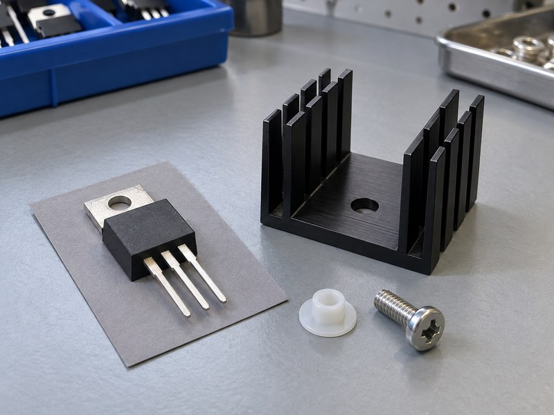
A linear voltage regulator heat sink carries away loss from a pass element that controls the output voltage. During normal regulation, the difference between electrical input power and useful output power mostly becomes heat in the device. Higher load current or a larger voltage drop usually increases that loss.
Calculate the intended operating point
For many linear designs, PD ≈ (VIN − VOUT) × IOUT + VIN × IQ is a useful starting equation, provided IQ matches the selected part’s current definition. As an illustrative comparison, 12 V to 3.3 V at 0.3 A creates about 2.61 W before the ground-current term. A nominally small output load can still produce a meaningful thermal requirement when the voltage difference is large.
- Record the voltage at the regulator’s terminals.
- Include sustained output current and applicable ground loss.
- Check the credible high-input and high-load combination.
Keep delivered power separate
The 3.3 V load in that example receives 0.99 W, while the regulator dissipates roughly 2.61 W. A sink is selected for the latter heat input, not the total power entering the board. Label each quantity in the calculation so a later electrical revision cannot silently change the thermal assumption.
| Illustrative quantity | Result, excluding IQ |
|---|---|
| Input power | 3.6 W |
| Load power | 0.99 W |
| Regulator loss | 2.61 W |
Calculate the power that enters the cooled device’s thermal path.
2. Does an LDO need less cooling automatically?
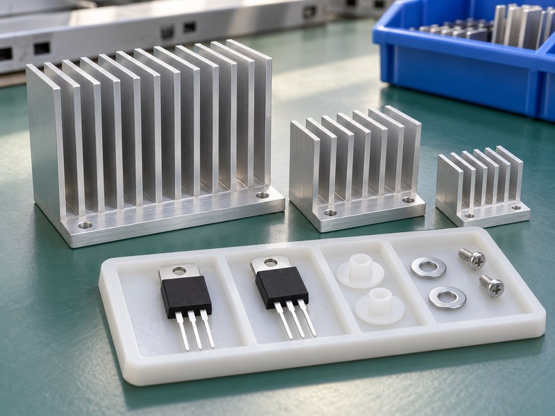
An LDO does not automatically need a smaller linear voltage regulator heat sink. Low dropout permits operation with a smaller voltage difference, but the circuit must actually use that lower input voltage to reduce pass-element loss. Supplying an LDO from an unnecessarily high rail can retain most of the thermal problem.
Compare operating voltage differences
At a 0.3 A load, reducing 5 V to 3.3 V creates approximately 0.51 W before ground-current loss, compared with 2.61 W for 12 V to 3.3 V. Those example values illustrate an electrical design choice, rather than a guarantee for every LDO. Check dropout behavior, ripple and regulation requirements across temperature before lowering the input rail.
- Use the device’s specified dropout conditions.
- Include minimum input voltage and supply ripple.
- Check startup and transient load behavior.
Review ground-current behavior
Ground current can vary with regulator topology and operating point. A typical no-load figure may not represent loss near maximum load or dropout. Use the relevant datasheet curves and limits, or measure the behavior when the available information does not cover your operating state.
| Design change | Thermal implication |
|---|---|
| Lower actual input voltage | Can reduce pass-element loss |
| Same high input rail | LDO label alone saves little heat |
| Different ground-current behavior | May change total device loss |
Choose the rail and regulator together before deciding how much cooling is needed.
3. Which package thermal path should you cool?
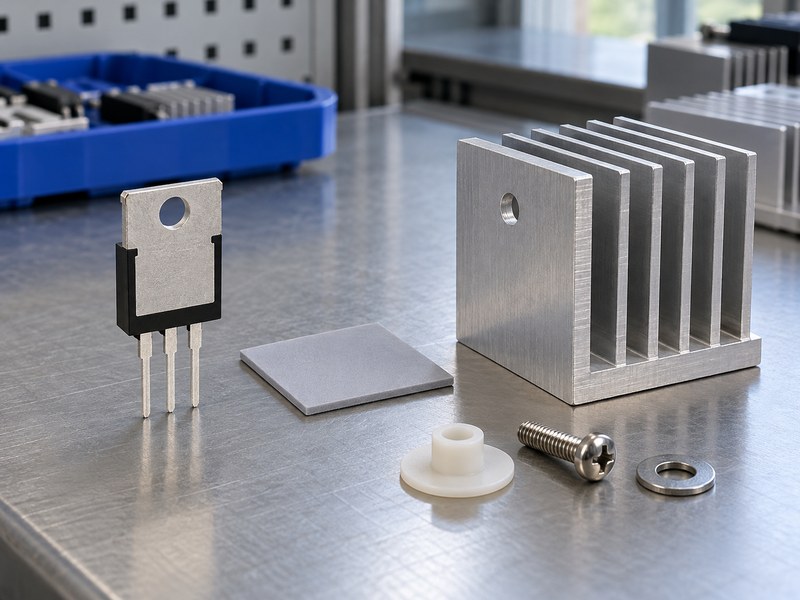
A linear voltage regulator heat sink should connect with the package surface that provides a useful specified thermal path. Through-hole tabs and soldered exposed pads behave differently. The molded top of a small package may be a less effective path than its connection into board copper.
Read the exact thermal information
Check the selected ordering code, package and thermal-metric definitions in its technical information. Junction-to-case top and bottom values refer to different surfaces, while junction-to-ambient values depend on a defined test arrangement. A characterization parameter used to estimate junction temperature from a top measurement should not be substituted casually for a case resistance in a series sink model.
- Identify the surface that touches the proposed cooling part.
- Read the metric definition and test conditions.
- Keep PCB and chassis paths distinct where they run in parallel.
Match the physical construction
For a metal-tab package, a suitable board-level heat sink can provide a defined mounting path. An exposed-pad regulator may need improved copper area, thermal vias or another board-aware solution instead. Select the attachment after reviewing the package construction and available assembly process.
| Package construction | Cooling path to review |
|---|---|
| Exposed through-hole tab | Tab, interface and sink |
| Soldered exposed pad | Pad, solder and PCB structure |
| Small molded package | Manufacturer-defined package and board paths |
Make the thermal model describe the same surface the hardware actually cools.
4. How do you set the sink’s thermal resistance target?
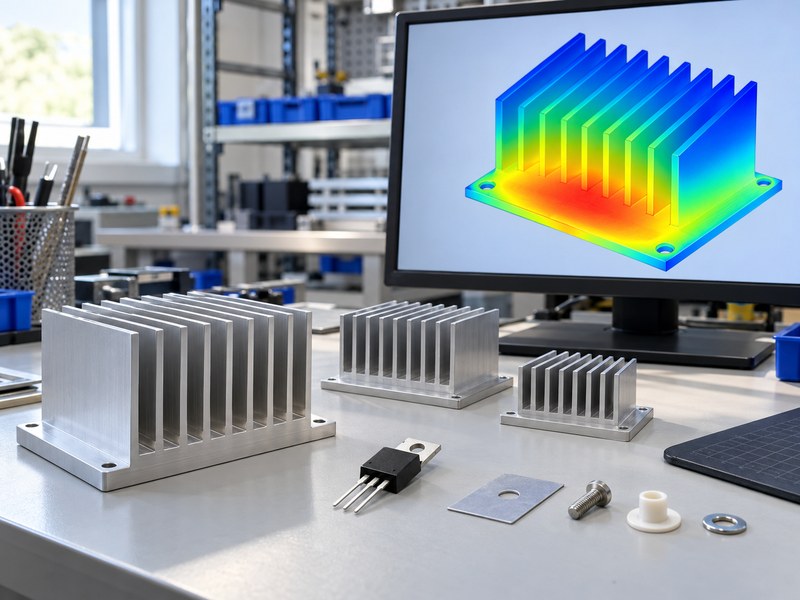
Set a linear voltage regulator heat sink target from allowed junction rise after accounting for the package and mounting interface. For a suitable steady-state series model, RθSA ≤ (TJ,target − TA)/PD − RθJC − RθCS. Choose the junction target from the device’s operating limits and your application margin.
Use local air temperature
Suppose an example design dissipates 2 W in 50°C local air with a 110°C junction target. Its complete thermal budget is 30°C/W. If the applicable package and interface paths total an assumed 6°C/W, the sink allowance is 24°C/W under the intended installation conditions.
- State each assumed value and its source.
- Use the hottest credible local inlet air.
- Keep thermal shutdown outside normal operating acceptance.
Check the remaining margin
A quoted sink rating is useful only if its orientation, airflow and heat input suit the application. If a calculated result leaves little margin, investigate uncertainty before accepting it. Package or interface resistance may dominate, in which case changing fins alone provides limited improvement.
| Illustrative budget | Value |
|---|---|
| Available temperature rise | 60°C |
| Total allowed resistance | 30°C/W |
| Sink allowance after local paths | 24°C/W |
The target belongs to a stated operating condition, rather than to a package name alone.
5. Can PCB copper replace a separate heat sink?
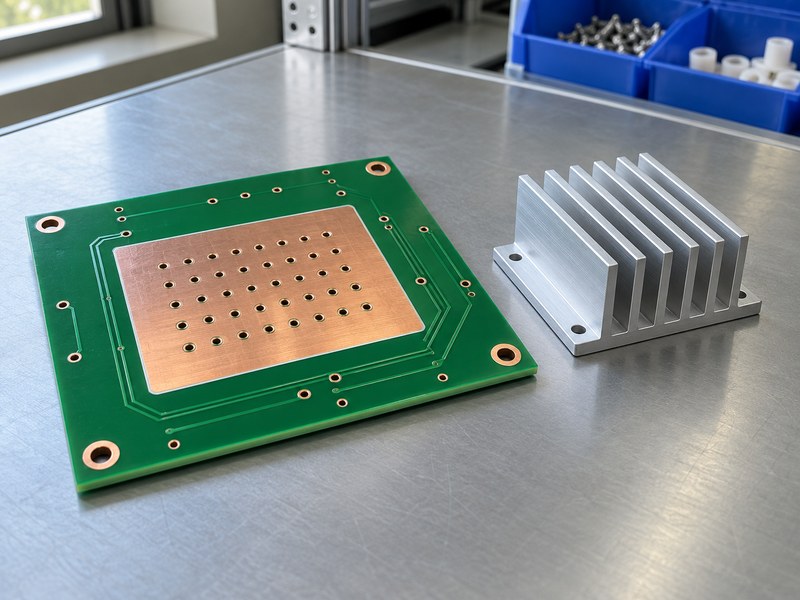
PCB copper can replace a separate linear voltage regulator heat sink when the assembled board keeps the junction within its target. That depends on package attachment, copper distribution, vias, layer structure and surrounding conditions. A datasheet’s board-dependent RθJA value is not automatically the value of your layout.
Follow the layout guidance
Use the manufacturer’s recommended exposed-pad land and soldering requirements. Review thermal vias, copper connections and electrical clearances with the board designer before changing them. A large visible copper patch may still spread heat poorly if narrow connections or an unsuitable stack-up restrict its path.
- Review the copper connected with the package’s thermal node.
- Check layer and via construction, including manufacturing limits.
- Include neighboring heat sources and enclosure clearance.
Compare the installed alternatives
An added sink can consume height, increase mass and introduce another interface. A board change may reduce part count but increase board area or manufacturing requirements. Compare each proposed board-level cooling arrangement at the same electrical load and ambient conditions.
| Proposed solution | Evidence needed |
|---|---|
| More board copper | Layout-specific thermal result |
| Added thermal vias | Stack-up and assembly confirmation |
| Separate sink | Defined package contact and support |
Choose the path that can meet the target in the finished assembly.
6. What interface and insulation does the package need?
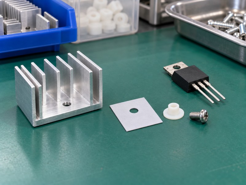
A linear voltage regulator heat sink needs an interface compatible with its contact geometry and electrical arrangement. Read the tab or exposed-pad potential for the exact device. A conductive mounting surface may need insulation from the sink, chassis or other devices sharing the same metal.
Review the complete stack
A tab pad can be bypassed by a screw or clip that touches live metal. Specify shoulders, washers or the appropriate insulated mounting system where required. Include the chosen interface resistance in the thermal calculation and inspect pad coverage after tightening, when assembly movement may have changed its position.
- Verify tab potential for approved substitute devices.
- Check fasteners and brackets as conductive routes.
- Define finished electrical acceptance for the product.
Control force and thickness
Use heat sink mounting hardware with force limits suitable for the package and interface. More torque does not guarantee lower thermal resistance; it can deform the tab or damage insulation. A controlled joint gives prototype measurements a better chance of representing production behavior.
| Interface decision | Thermal and electrical check |
|---|---|
| Pad material | Appropriate ratings and resistance |
| Assembled thickness | Contact and temperature drop |
| Fastener arrangement | Force and conductive bypass paths |
Release the interface and mounting hardware as part of the cooling design.
7. How should you handle changing or pulsed loads?
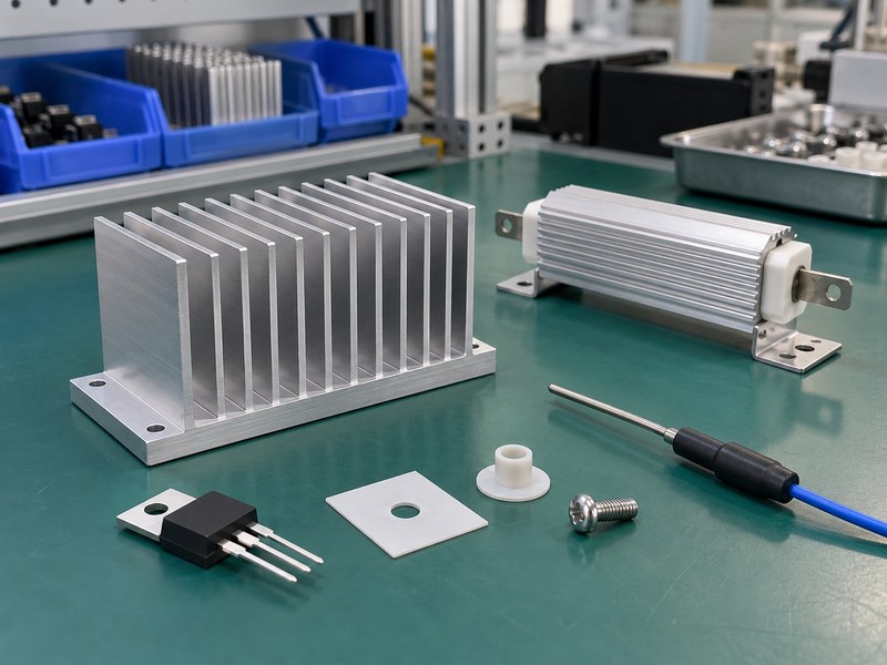
Changing loads can require more than a steady-state linear voltage regulator heat sink calculation. Average power may predict a long-term base temperature while missing a short junction-temperature peak. Pulse duration, repetition and package thermal response determine whether that approximation is useful.
Separate the time scales
A brief current pulse and a sustained overload can have the same peak loss but different thermal effects. Use transient thermal information when the manufacturer provides it, or an appropriate measured validation when it does not. Keep current-limit, safe-operating-area and electrical transient constraints in the review alongside temperature.
- Record the actual load waveform and repetition.
- Identify sustained states before averaging power.
- Check repeated pulses after the assembly is already warm.
Test meaningful sequences
Startup into a heavy load, hot restart and long operation near a current limit can expose conditions missed by a short open-bench test. Select sequences that reflect the product’s intended behavior. Record the initial temperature and cooling state so later tests can reproduce the same starting conditions.
| Load pattern | Thermal evidence |
|---|---|
| Sustained load | Steady-state loss and temperature |
| Short isolated pulse | Relevant transient response |
| Repeating pulse train | Peak behavior from a warm assembly |
Use the time history that the regulator will experience in service.
8. When should you reduce loss instead of adding fins?
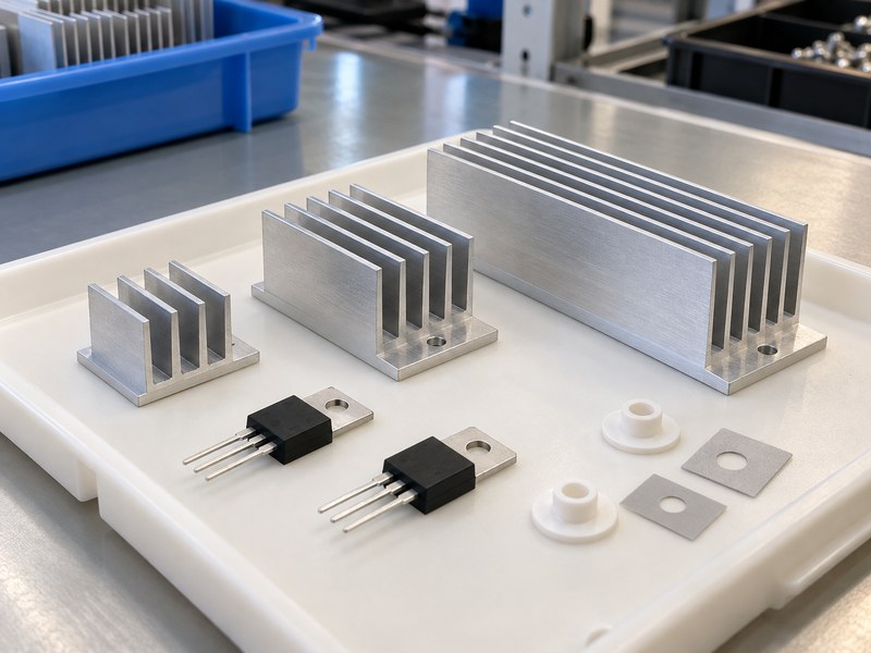
Reduce loss when a linear voltage regulator heat sink cannot meet the target within the available envelope or when cooling adds disproportionate size and complexity. Lowering actual input voltage, selecting another package or reviewing a preregulator can change the requirement. Each option also changes electrical behavior and needs evaluation.
Check the voltage-drop opportunity
The earlier 12 V to 3.3 V example dissipates approximately 2.61 W at 0.3 A before ground loss. Reducing the actual input to 5 V cuts that term to about 0.51 W. The lower rail still needs adequate headroom and the regulator’s required input conditions through ripple, tolerance and transients.
- Compare the credible input rails.
- Review dropout and regulation limits at temperature.
- Account for loss and heat in any added preregulator.
Compare the completed systems
A switching preregulator may reduce linear-stage heat but adds its own losses, components and noise considerations. A larger package may provide a better path but require board changes. Compare cost, thermal margin, electrical performance and production constraints using the complete proposed system.
| Change | Additional review |
|---|---|
| Lower input rail | Headroom and supply variation |
| Different package | Layout, contact and electrical equivalence |
| Preregulator | Distributed loss and system behavior |
Changing the electrical design can remove heat before the cooling hardware has to carry it.
9. What should you request from a heat sink supplier?
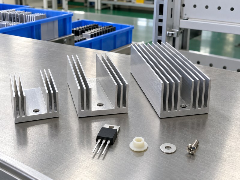
Request a linear voltage regulator heat sink against a documented load, temperature budget and mounting drawing. Include the actual package contact area and installed airflow. A supplier cannot compare designs reliably from output-current rating and a photograph alone.
Provide the usable envelope
For extruded heat sinks, show height, length, mounting face and permitted machining features. Include the enclosure relationship and any mass or support constraints. Ask for the conditions behind quoted thermal resistance and agree on how a sample will be evaluated.
- Supply device loss at the intended operating corners.
- State local air temperature, orientation and flow conditions.
- Include interface and electrical isolation requirements.
Request comparable alternatives
A standard profile with a machined mounting land may meet the target without new tooling. A custom base or contact pocket may justify a machined construction. Compare alternatives by the tested assembly and manufacturing requirements, rather than selecting the part with the largest visible fins.
| RFQ input | Supplier decision |
|---|---|
| Thermal budget | Required cooling performance |
| Contact drawing | Base and mounting construction |
| Quantity and acceptance | Production route and sample plan |
Give the supplier the conditions that will determine whether the finished part passes.
10. How do you approve the design for production?
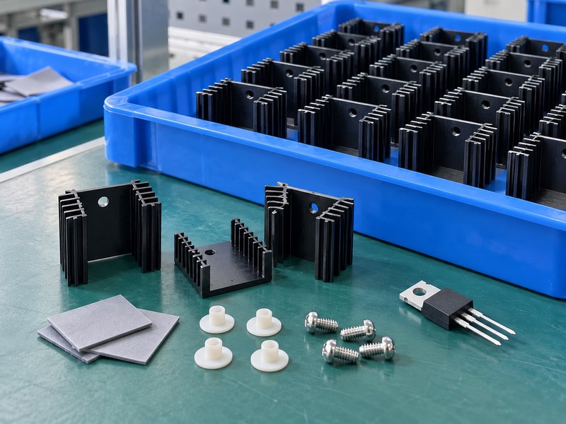
Approve a linear voltage regulator heat sink after the complete assembly meets its thermal, electrical and mechanical acceptance requirements. Use the final package, interface and mounting process. Keep the calculated operating range and measured results with the released drawing.
Validate the installed configuration
Measure relevant package and sink temperatures using appropriate thermal metrics and sensor methods. Include the final enclosure, cooling arrangement and neighboring heat sources. If the result differs from the model, check actual loss and boundary conditions before changing assumed resistance values merely to fit one test.
- Test credible high-loss and high-ambient states.
- Record interface grade and fastening conditions.
- Review repeatability and approved substitutions.
Prepare the engineering handoff
When you contact us, send the package drawing, calculated loss, available envelope and prototype observations. We can discuss the cooling and mounting options against those inputs. Use the agreed acceptance method to decide which configuration is ready for repeat orders.
| Release record | Purpose |
|---|---|
| Operating envelope | Defines the supported load and ambient range |
| Test report | Documents the installed assembly’s behavior |
| Controlled drawing | Reproduces contact and mounting details |
Retest changes that alter loss, contact, insulation or installed cooling conditions.
Q1: Can I use an LDO without an external sink?
Yes, if the package and board keep the junction within its target under the intended conditions. Calculate the loss and validate the assembled board.
Q2: What’s the best way to reduce linear-regulator heat?
Reducing the actual voltage drop can reduce loss substantially. Check required headroom, ripple and transient conditions before changing the input rail.
Q3: How do I know if the PCB is the main cooling path?
Read the package and layout guidance. Exposed pads and specified copper areas often indicate a deliberate board path, but the exact construction needs review.
Q4: Can I rely on thermal shutdown during normal operation?
No. Shutdown cycling indicates that the operating condition exceeds the intended thermal design. Correct the loss or cooling arrangement before release.
Q5: Can I replace the regulator with another same-size package?
Only after checking electrical behavior, tab potential, thermal metrics and mounting requirements. Matching outlines do not establish an equivalent cooling path.