
Choose an anodized cold forged aluminum heat sink by matching its material, pin geometry, forming route, and finish to your assembly. A dense pin array can look convincing in a rendering yet fail during forming, airflow testing, or mounting. You can reduce that risk by developing material, geometry, tooling, finishing, and assembly validation as one manufacturing route.
1. How is an anodized cold forged aluminum heat sink made?
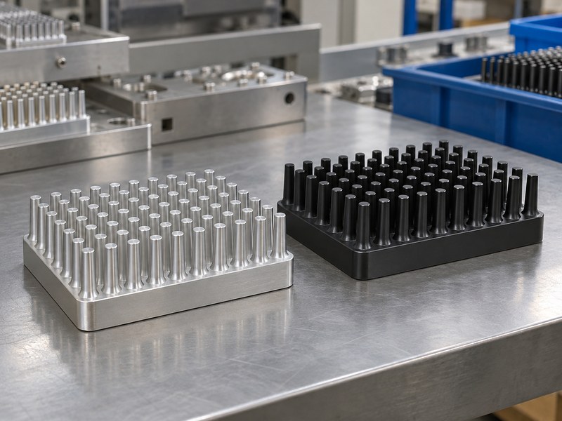
An anodized cold forged aluminum heat sink is made by plastically forming an aluminum blank in tooling, completing required machining, and anodizing specified surfaces. Cold forging describes the forming stage; anodizing describes a later surface treatment. Neither term, by itself, establishes alloy, dimensions, thermal performance, or whether every mounting feature emerges directly from the die.
Which features can form as one piece?
Suitable tooling can form the base and pins integrally, removing a separate joint between them. This gives heat a continuous metallic path into the fins, but the source still has to spread heat through the base and transfer it into moving air. The device interface, mounting pressure, and enclosure airflow still need review.
- Separate forming, machining, and finishing operations.
- Identify which features remain integral after processing.
- Review the complete assembly heat path.
What should a process drawing show?
Mark the blank, formed shape, machined features, and finished condition as distinct steps. If a geometry requires warm forming or several forming stages, name that route accurately. The drawing should describe the actual production method rather than using cold forging as shorthand for every pressure-formed heat sink.
| Stage | Output requiring agreement |
|---|---|
| Forming | Base and pin geometry |
| Machining | Contact face and mounting features |
| Finishing | Coated and masked surfaces |
Review the sequence before approving tooling.
2. Which aluminum material suits the forging route?
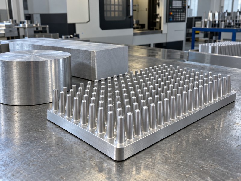
The right material for an anodized cold forged aluminum heat sink balances conductivity, formability, strength, thread requirements, and finishing behavior. Commercially pure aluminum and suitable aluminum alloys can support different design priorities. Choose an identified grade and starting condition with the forming specialist rather than assuming every aluminum material can fill the same pin geometry under the same conditions.
Why does starting condition affect feasibility?
Material must flow into narrow die cavities while resisting fracture and excessive forming load. Its response depends on composition, temper, prior processing, and the proposed deformation. A material selected only from a conductivity table may create difficulties when the part also needs deep pins, structural mounting ears, or repeatedly serviced threads.
- Specify grade and incoming material condition.
- Confirm the intended forming and heat-treatment sequence.
- Review thread loads and local bearing surfaces.
What should the design team compare?
Compare the finished part’s requirements rather than ranking alloys on one property. Include conductivity information relevant to the final material condition, mechanical checks at mounting points, and representative anodized appearance. If heat treatment changes the condition after forming, revisit dimensional control and any assumptions used in the thermal model.
| Requirement | Material decision |
|---|---|
| Heat spreading | Relevant conductivity data |
| Forming feasibility | Flow and damage assessment |
| Mounting strength | Finished condition and local geometry |
Select the grade after reconciling those requirements.
3. Which pin geometry works with the available airflow?
An anodized cold forged aluminum heat sink should use pin geometry that fits the actual airflow direction, pressure availability, mounting orientation, and operating environment. Round, elliptical, and other feasible sections offer different flow paths and manufacturing demands. Shape freedom helps only when the proposed array can receive useful airflow and can be formed consistently.
How should you compare pin arrangements?
Compare aligned and staggered layouts inside the available envelope. Include bypass around the array, nearby obstructions, and the fan’s response to system resistance. A tightly packed design may present more surface while moving less air through the region that needs cooling; free-air fan ratings cannot resolve that balance.
- Model surrounding clearance and likely bypass paths.
- Include fan and duct behavior in forced-air comparisons.
- Check installed orientation for passive cooling.
What changes when airflow direction varies?
Pin arrays can admit air from more directions than a continuous plate-fin channel, but directional sensitivity does not disappear. An elliptical pin has an orientation; nearby walls can block access; and local flow can differ from the inlet direction. Test the arrangement under plausible installation conditions rather than selecting from a top-view pattern alone.
| Array choice | Question to investigate |
|---|---|
| Round pins | Can air reach the interior? |
| Elliptical pins | Is orientation controlled? |
| Staggered rows | What happens to system resistance? |
Judge the array by assembly temperature and airflow together.
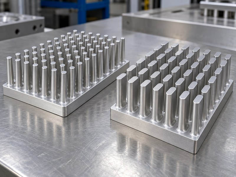
*Round and obround pin examples; forming feasibility and airflow suitability depend on the specific design.*
4. How do pin height, spacing, and base thickness interact?
Pin height, spacing, and base thickness determine how an anodized cold forged aluminum heat sink spreads heat and exposes useful surface to air. More height adds area but also extends the conduction path along each pin. A thicker base can improve spreading in some layouts while adding mass, envelope demand, and manufacturing implications that the design must evaluate.
Where should you spend the available material?
Start from the heat-source footprint and mounting constraints. A small source beneath a wide array may require more attention to base spreading than a broad heater does. Increasing pin count around a poorly supplied region will not necessarily reduce the hottest device temperature, particularly if the additional pins restrict air access.
- Map source footprint against the available base area.
- Compare base thickness and pin geometry together.
- Track device temperature rather than surface area alone.
How should you present a design study?
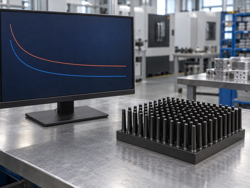
Compare candidate geometries under consistent boundary conditions. A conceptual curve can explain competing effects, but only a model or test tied to a defined assembly can predict a temperature. State what changed between candidates and which constraints remained fixed.
| Parameter | Coupled effect |
|---|---|
| Pin height | Area and fin conduction |
| Pin spacing | Surface count and airflow access |
| Base thickness | Spreading, mass, and forming route |
Choose dimensions from the coupled comparison. The conceptual plot below illustrates qualitative trends rather than measured data or guaranteed product performance.
5. What determines whether the die fills completely?
Die fill in an anodized cold forged aluminum heat sink depends on available material volume, material flow, friction, cavity geometry, and the forming sequence. A feasible machined prototype does not prove that a forged version will fill every pin. The forming review needs its own evidence before the team commits to production tooling.
Where can incomplete filling appear?
Check pin height across central, outer, and locally dense regions. Material may favor some paths while other cavities remain short, especially when the geometry demands uneven flow. Forming simulation can investigate candidate routes, but assumptions about friction, material behavior, and boundary conditions need support from process experience and trial results.
- Reconcile blank volume with the proposed formed shape.
- Examine fill at difficult and isolated features.
- Compare predicted load with the planned equipment.
How do you separate thermal and forming decisions?
Keep both assessments visible during iteration. A pin change that helps air movement can alter cavity filling, tool loading, or blank requirements. Record those consequences before choosing a revision; a thermal model should not silently define a geometry the manufacturing route cannot reproduce.
| Forming concern | Evidence to review |
|---|---|
| Short pins | Fill prediction and trial measurements |
| Excessive load | Load estimate and equipment assessment |
| Uneven flow | Blank, friction, and stage review |
Approve the route after checking representative difficult features.
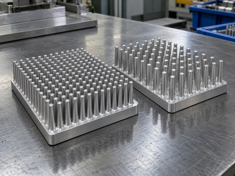
*These arrays vary in density and geometry; they do not isolate either variable in a forming or thermal comparison.*
6. How should tooling and ejection shape the design?
Tooling for an anodized cold forged aluminum heat sink must form the geometry, withstand its loading, and release the part without unacceptable damage. Pin slenderness, cavity access, radii, parting features, and ejection arrangements belong in the early design discussion. Universal draft-angle or aspect-ratio rules cannot replace a review of the specific die and process.
Which details make a thermal shape difficult to manufacture?
Abrupt transitions, crowded mounting features, and unsupported slender pins can complicate tool construction or part handling. An attractive pin pattern may also leave little space for practical ejection features. Ask the tool designer to identify which surfaces move, where the part receives support, and which features need a manufacturing allowance.
- Agree allowable radii and geometric departures.
- Identify ejection and handling contact areas.
- Review tooling access around mounting features.
What should the trial demonstrate?
Inspect the part after release and handling, not only while it appears intact in the die. Look for bent pins, local marks, cracks, and dimensional changes that affect airflow or mounting. Define how tool maintenance and wear will be monitored using features that a production inspector can measure reliably.
| Tooling topic | Design review output |
|---|---|
| Geometry release | Approved radii and allowances |
| Ejection | Permitted contact zones |
| Tool condition | Inspection and maintenance indicators |
Put accepted manufacturing allowances on the drawing.
7. Which features should be machined after forging?
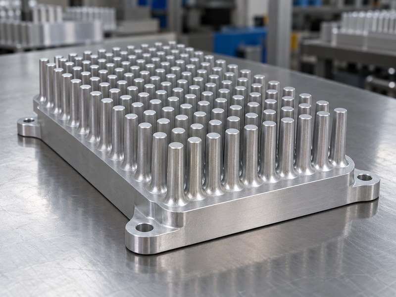
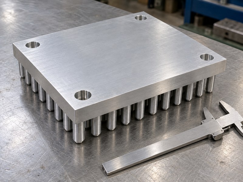
An anodized cold forged aluminum heat sink may need machining for its contact face, mounting holes, threads, locating features, or other precision interfaces. Identify those operations from the assembly requirements rather than assuming forging delivers every finished tolerance. The machining plan must also support thin pins and preserve the datums used to locate the heat source.
How do you protect the integral array?
Choose workholding that supports the base without crushing or bending pins. Define the datum scheme before cutting a mounting pad so holes, contact surfaces, and locating features share a consistent reference. Inspect contact-face geometry after the operations that could change it, including later finishing where relevant.
- Define assembly datums and functional dimensions.
- Support the base during precision machining.
- Remove burrs without damaging nearby pins.
Where does process sequencing affect the drawing?
Threading, deburring, cleaning, masking, and anodizing need an agreed sequence. A post-finish cut can expose bare aluminum; an unmasked thread can change its fit after coating. Make these decisions visible on the process plan and specify finished acceptance for surfaces that must mate with other parts.
| Feature | Process decision |
|---|---|
| Contact pad | Machining and masking sequence |
| Threaded hole | Finished fit and surface treatment |
| Locating feature | Datum and dimensional inspection |
Inspect the interfaces in their delivered condition.
8. How should anodizing and masking be planned?
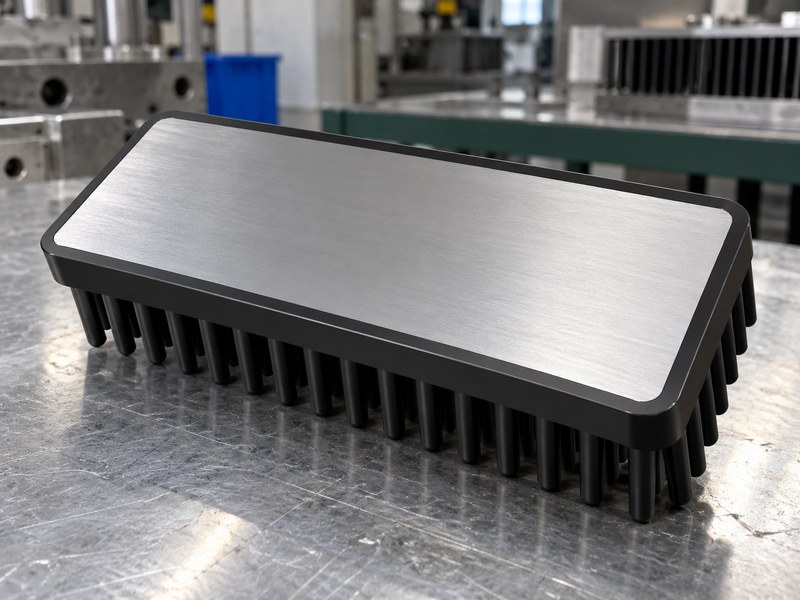
Anodizing for an anodized cold forged aluminum heat sink should protect selected surfaces while respecting thermal contacts, electrical bonds, and precision fits. Specify the finish after reviewing the entire pin array and its interfaces. Dense geometry also needs practical provisions for cleaning, rinsing, drainage, racking, and inspection, rather than approval from a flat color sample alone.
Which surfaces need different treatment?
The external fins, device contact pad, mounting threads, and grounding point may perform different jobs. Oxide can aid corrosion resistance and alter radiation behavior while creating a different interface condition at a contact surface. Identify masking boundaries and permissible rack marks on the part drawing before sample finishing.
- Map coated surfaces and exposed functional regions.
- Keep rack marks away from controlled interfaces.
- Confirm inspection access within the pin array.
How should samples be approved?
Approve appearance on the intended alloy and a representative complete part. Check masked boundaries, trapped residues, and the condition of machined interfaces after treatment. Evaluate thermal performance with the actual interface material and mounting method so a cosmetic approval does not become an unsupported cooling claim.
| Surface | Acceptance focus |
|---|---|
| Pin array | Coverage, cleanliness, and appearance |
| Contact pad | Boundary and interface condition |
| Grounding point | Defined conductive connection |
Keep finish acceptance separate from assembly thermal acceptance.
9. How do you verify the finished design?
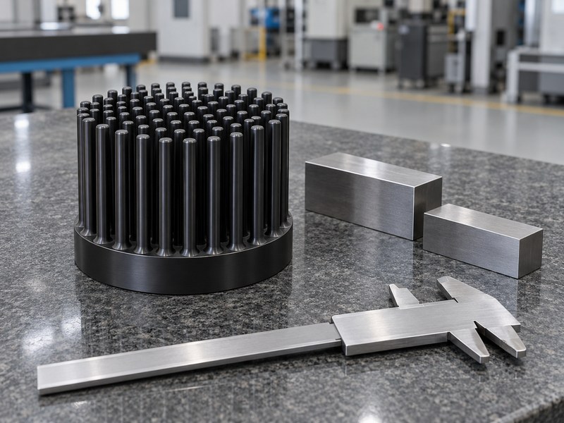
Verify an anodized cold forged aluminum heat sink through dimensional, material, finish, and assembly thermal checks tied to its requirements. Use representative formed parts for manufacturing approval. A machined development model can test a thermal concept, but it cannot demonstrate die fill, production pin straightness, tool wear behavior, or the final finishing route.
What should the thermal test reproduce?
Match heat input, source footprint, interface material, clamping, orientation, airflow, and nearby obstructions to the intended application. Measure device and base temperatures where possible. If infrared imaging supports the test, account for surface emissivity rather than comparing coated and bare regions under an unverified common camera setting.
- Record the finished geometry and sample identity.
- Control installation and operating conditions.
- Retest when a change affects the heat path.
Which defects deserve separate inspection?
Measure pin height and position across the array rather than checking only its outer envelope. Inspect the contact face, mounting features, and finish boundaries as separate functional groups. When a trial fails, connect the defect with its likely process stage before changing the thermal design to accommodate it.
| Verification group | Evidence |
|---|---|
| Formed geometry | Pin and base inspection |
| Assembly interfaces | Fit, flatness, and mounting check |
| Thermal operation | Controlled assembly test record |
Use the evidence to decide which changes require another trial.
10. How do you move from samples into repeat production?
Move an anodized cold forged aluminum heat sink into repeat production after representative parts meet the approved drawing, process route, and assembly tests. Scale-up needs evidence that the route repeats across a planned run, including machining and finishing. A single successful sample leaves variation, handling, inspection frequency, and process-change control unresolved.
What should the pilot run establish?
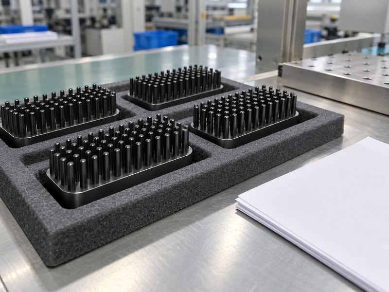
Track material condition, forming stages, dimensional results, machining, and finishing by lot. Compare central and outer pins, contact-face condition, and handling damage across the run. Use those results to define inspection points sensitive to tool condition or process variation.
- Retain approved drawing and process revisions.
- Connect inspection records with production lots.
- Protect pins and contact faces during packaging.
How should the next engineering review start?
Send the heat-source map, envelope, airflow, mounting scheme, material preference, and expected production demand when you contact us. Include the proposed finish map and existing trial results. Those inputs let the review address geometry, forming feasibility, interfaces, and the evidence needed before release.
| Release item | Required agreement |
|---|---|
| Manufacturing route | Approved forming and machining sequence |
| Functional performance | Accepted dimensional and thermal evidence |
| Repeat production | Inspection, packaging, and change controls |
Close unresolved process assumptions before approving the production revision.
FAQ
Q1: Can I use the highest-conductivity aluminum available?
Only if it also meets forming and mechanical requirements. Check the starting condition, finished strength, thread loading, and proposed pin geometry before choosing a material from conductivity data alone.
Q2: What’s the best pin spacing for natural convection?
There is no universal spacing. Compare candidate arrays at the installed orientation with realistic clearances, heat input, and ambient conditions; a dense array can obstruct the buoyant airflow it needs.
Q3: How do I know whether the proposed pins can be forged?
Request a geometry-specific forming assessment and representative trials. Review cavity filling, load, ejection, and dimensional results instead of treating a general aspect-ratio claim as approval of your drawing.
Q4: Can I validate production with a machined prototype?
You can validate parts of the thermal concept, but production approval needs formed samples. Machining does not reproduce die fill, ejection effects, or variation from the proposed forming route.
Q5: Should I anodize the device contact face?
Decide from the complete interface requirements. Evaluate coating resistance, flatness, interface material, clamp load, electrical behavior, and corrosion exposure before specifying a coated or masked contact pad.